NANJG AK47 1050mA 4-Group Driver
Reviewer's Overall Rating: ★★★★★
Summary:
| Size: | 17mm |
| Voltage: | 2.6-4.5V |
| Regulation |
Linear Regulator |
| Current: | 1050mA |
| Modes: | 2-5 in 4 groups |
| Price Paid: | $3.19 |
| From: | DealExtreme KaiDomain |
Pros:
- Customizable number of modes
- Well regulated
- Very efficient
- Nicely spaced group of 3 modes
- No PWM on low
Cons:
- Group selection requires soldering
- Difficult to solder to board correctly
- Mode memory a little odd
- Narrow voltage input range (1 li-ion cell only)
Features / Value: ★★★★★
Mode Groups
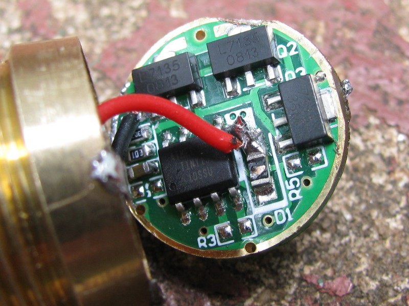
This driver is one of those hidden gems on DealExtreme, where they don't even know what they have. DX advertises it as a 5-mode driver, but like the NANJG 112A driver I reviewed earlier, available at KD, this driver has 4 stars on the back and offers 4 different groups of modes. In fact they seem to be the same four mode groups. Unaltered, you get Low-Medium-High-Strobe-SOS. But by soldering a connection from the outer ring on the bottom of the board to each star on the back of the board you get:
1st star: Low and High
1st and 2nd star: Low, Medium, and High
1st thru 3rd stars: Low, High, Slow Strobe
The 4th star is connected to the ground ring internally already, so it doesn't do anything.
I was particularly impressed with the 3-mode version which has a very nice Low, and a decent Medium. KaiDomain sells this same driver, advertising it as two modes. Looking at the board, the only difference I notice is on the left side of the picture above near the ATMEL chip, there are 4 components lined up whereas the DX board is missing the one at the bottom. Both boards are still missing what is labelled as R3 and R5 at the bottom side of the chip. KD also has better diagrams that show where to solder the leads.
Installation
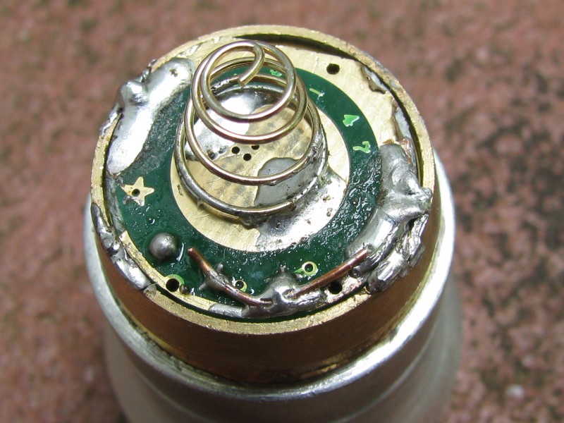
I didn't take any "before" shots, so the driver looks messy. I had a horrible time soldering to this board. I thought it was broken for a while because on my first try it only had one mode. Then I got all the modes except High which would revert to Low. Turned out I had just done some messy soldering, which is easy with how tightly packed everything is. Once I got it working, it was fine.
Sorry, the soldering looks really awful I know. I have an excuse ready though. If I had just tried out the one star, I would have done a better job. But what really messes it up is trying to solder from the board to the pill. The solder just doesn't want to get on the pill because it dissipates the heat so fast. So I wind up overheating everything and globbing tons of solder on there. Then I am doing testing and had some problems, so I had to unsolder and resolder. Then I took it out of the light I had it in and put it in a different light, so this thing has really been around the block at this point.
Mode Memory and Mode Switching
Like the 112A, the mode memory is based on how long the light is On. So if it stays on for more than a few seconds, it will stay in that mode when you turn it off and back on, whether that is a quick half-press or leaving it in your pocket for an hour. It counts as memory, but I'm not crazy about it.
Build Quality: ★★★★★
Build quality seems good even though the board is too crowded. I'm amazed actually at how much abuse these drivers can take. During one iteration I connected the battery and something was shorted out because smoke started coming from the board. It was just for a second, but the board still works! Also, I have a regular size soldering iron and would hit all kinds of stuff with it trying to get the wires connected and could smell stuff burning (usually just the plastic on the wire leads) but it still works.
Battery Life: ★★★★☆
Here is a runtime test using my Ultrafire WF-502B as a host and running a Cree XP-G R5 cool white LED. The battery is a protected gray Trustfire 2400 mAh lithium-ion. This test shows how amazingly consistent the draw is using linear regulators. The battery voltage is measured without a load and the current is measured at the tail. 85 minutes is kind of disappointing, but the good thing is you are getting consistently high output for almost the entire time whereas many drivers will start off high and then draw lower and lower current as the light gets dimmer (see my review of the 502B with its original driver).
| Time (hr:min) | Volts (V) | Current (mA) |
|---|---|---|
| 0:00 | 4.21 | 1050 |
| 0:15 | 4.03 | 1030 |
| 0:30 | 3.92 | 1030 |
| 0:45 | 3.81 | 1030 |
| 1:00 | 3.71 | 1030 |
| 1:15 | 3.63 | 1000 |
| 1:25 | 3.58 | 920 |
I did some measurements for efficiency with 4 different 18650 batteries at various states of discharge. First I measure the voltage of the battery at rest (V rest). Then I measure voltage and current at the battery with the LED on (V in and I in) and then the voltage drop across the LED and the current to the LED (V out and I out). I only have 2 DMM's, so I am only taking two of the readings at a time, then reconfigure it and measure all 4 batteries again. Since I'm only running the LED for a few seconds at a time, I think this works, but the LED is pretty much always fairly cool. Power is just volts times amps to get watts and efficiency is P out / P in. With the 112A driver I was getting about 60% efficiency, but with the 3 linear regulators, this thing runs very efficiently, with the efficiency getting better and better as the voltage drops since the linear regulators waste extra voltage as heat. It seems unlikely that at 4.19V the current out would be higher than the current in, but that's what I measured. If I use 1050mA for I out at that data point, then the efficiency would be 83% instead of 85%. Same kind of thing goes for the measurements at 3.63V, only if I make that common sense change, it would drop the efficiency from 98% to 92%.
| At rest battery voltage | 3.63 | 3.83 | 4.05 | 4.19 | |
| High | V in (volt) |
3.55 | 3.71 | 3.91 | 4.04 |
| I in (mA) |
850 | 1050 | 1060 | 1050 | |
| P in (watt) |
3.02 | 3.89 | 4.14 | 4.24 | |
| V out | 3.28 | 3.37 | 3.38 | 3.37 | |
| I out | 900 | 1050 | 1060 | 1070 | |
| P out | 2.95 | 3.54 | 3.58 | 3.61 | |
| Efficiency | 98% | 91% | 86% | 85% | |
| Med | V in | 3.61 | 3.79 | 4.00 | 4.13 |
| I in | 240 | 300 | 320 | 320 | |
| P in | 0.87 | 1.14 | 1.28 | 1.32 | |
| V out | 2.56 | 2.59 | 2.61 | 2.61 | |
| I out | 230 | 280 | 320 | 320 | |
| P out | 0.59 | 0.73 | 0.84 | 0.84 | |
| Efficiency | 68% | 64% | 65% | 63% | |
| Low | V in | 3.63 | 3.82 | 4.04 | 4.16 |
| I in | 30 | 40 | 40 | 50 | |
| P in | 0.11 | 0.15 | 0.16 | 0.21 | |
| V out | 2.27 | 2.28 | 2.28 | 2.28 | |
| I out | 30 | 30 | 40 | 40 | |
| P out | 0.07 | 0.07 | 0.09 | 0.09 | |
| Efficiency | 63% | 45% | 56% | 44% |
I don't know how much value the readings are for Medium and Low since I have a pretty cheap DMM and the PWM of the driver's controller will play havoc with the accuracy of the readings. I got consistent, clear readings, but they are probably only catching the peak current instead of taking account the rapid pulsing of the PWM.
Light Output: ★★★★☆
Delivering 1.05A to the LED provides pretty good output, and the driver maintains that level for most of the battery charge, down to 3.8V. Supposedly you could get another 7135 chip and solder it on top of one of the 3 chips on the board to get 1.4A output. That would really crank but also reduce light efficiency since the LED is more efficient at lower currents.
Summary: ★★★★★
The 3 modes are spaced just about perfectly (5%, 30%, and 100%) and the driver is very efficient while providing a constant level of output. Despite being difficult to solder leads to the board and then having to solder the stars on the back, this makes for a very good driver once it is in place. It would be great if it was available with 4 7135 regulators for higher output, but even 1 amp provides very good output from XP-G LED's.
