I put together this simple flashlight example code for the ATTiny10 after a request from Microa in my PIC quickstart thread, but it didn't seem appropriate to post there. Hopefully it will help anyone getting started with coding for ATTiny devices. This implements a simple 3-level light plus off using a momentary switch and includes voltage monitoring. I hope it can provide a foundation for anyone who wants to develop their own UIs. Let me know if there are any questions about the implementation
//v0 5/1/2014 by Everett
//initial version
//simple flashlight controller. mode change on power cycle
//v1 5/3/2014 by Everett
//adapted to momentary switch
//v2 5/6/2014 by Everett
//ported to Attiny10 device
{
    isr_prescale++;
    if(isr_prescale>=4){ //prescale since timer only has the 4kHz option
        isr_prescale=0;
        debounce();
        if(++v_timer==voltage_rate){v_timer=0; v_sample=1;}
    }
}

ISR(INT0_vect)
{
    //no action, but ISR must be included since it will execute upon waking
}


int main(void)
{
    configure();    //set up hardware peripherals

    mode=default_mode;
    initialize_mode();
    pressed=0; new_press=0; switch_count=10;
    sei();  //turn on interrupts

    while(1){

        if(v_sample){
            v_sample=0;
            if(mode==max){              //if battery goes below threshold in max mode, force down to medium mode
                if(read_voltage()<100){  //set threshold for external voltage here
                    mode=med;
                    initialize_mode();
                }
            }
        }

        if(new_press){
            new_press=0;
            mode++;
            if(mode>max_mode) mode=0;
            initialize_mode();
        }

        if(mode==off)
        {
            shutdown(); //shutdown will lock up here until a press wakes the device
        }

    }
}

void shutdown(void)
{
    TIMSK0=0;   //stop timer interrupt
    pwm=0;  //zero output
    TCCR0A=0; //turn off pwm
    #ifdef pwm_invert
    PORTB|=0b00000010;
    #else
    PORTB=0;        //ensure pin is low
    #endif
    ADCSRA=0;   //adc off
    PRR=3;  //power reduce on adc and timer0

    while(1)    //make this a loop so we stay here until sure the switch went down
    {
        do{
            debounce();
            _delay_ms((char)1);
        }while(pressed);    //ensure switch is up

        EICRA=0;    //interrupt on low level of int0
        EIMSK=1;
        SMCR=0b00000101;    //enable sleep
        sleep_cpu();
        EIMSK=0;
        SMCR=0b00000100;    //disable sleep

        pressed=0; switch_count=10;
        for(char i=0; i<40; i++){    //watch for up to 40ms for a solid press
            debounce();
            _delay_ms((char)1);
            if(pressed) break;  //if pressed break out of for loop
        }
        if(pressed) break;  //if pressed break out of sleep loop
    }

    configure();    //set up hardware for operation

}

void debounce(void)
{
    static char port_copy=0xff;
    #define switch_mask 0b00000001  //this selects PB0 as the switch

    if((PINB&switch_mask)==port_copy)   //if the current state matches previous state
    {
        if(--switch_count==0)   //count down samples. if 10 consecutive samples matched
        {
            switch_count=10;    //reset sample counter
            if(PINB&switch_mask) pressed=0; //if the state is high, switch is up
            else        //else switch is down. check for new press
            {
                if(pressed==0) new_press=1; //if last state of pressed was 0, this is a new press
                pressed=1;  //switch is now down
            }
        }
    }
    else    //state doesn't match,
    {
        switch_count=10;    //reset sample counter
        port_copy=(PINB&switch_mask);   //get new sample
    }
}

void initialize_mode(void)
{
    switch(mode){   //initialize current mode
        default:
        case max:
        pwm=255;
        break;
        case med:
        pwm=25;
        break;
        case low:
        pwm=1;
        break;
        case off:
        pwm=0;
        break;
    }
}

unsigned char read_voltage(void)
{
    ADCSRA|=(1<<ADSC);
    while(ADCSRA&(1<<ADSC));
    return ADCL;
}


void configure(void)
{
    PRR=0;
    TIMSK0=0b00000001;  //interrupt on t0 overflow
    pwm=0;
    #ifdef pwm_invert
    TCCR0A=0b00110001;  //output B inverted
    #else
    TCCR0A=0b00100001;  //output B on, not inverted, 8bit pwm,
    #endif
    TCCR0B=0b00001001;  //no prescale for 3906Hz pwm and interrupt
    GTCCR=0;

    PORTB=0;
    DDRB=0b00000010;    //PB1 output
    DIDR0=0b00000100;   //PB2 analog
    PUEB=0b11111001;    //pull up switch and reset

    ADMUX=2;    //PB2
    ADCSRA=0b10000011;  //

    SMCR=0b00000100;    //enable power down mode
}
Hi, thank you for posting the code, isn’t the tiny10 the sot23 style? I thought they could only be programmed in assembly and needed a special programmer, your code looks like C. Please do educate me as I’m a relative beginner to programming.
Yes it’s the sot23 package, which means you will need a special chip holder, or you can just solder wires to it temporarily to program. You can use the stk600 or the AVRisp and a few other programmers I think. You can use either language; personally I prefer assembly for something this small because of size constraints (the above code already uses 60% of flash), but C tends to be easier for beginners and easier for others to modify
Great, So kind you are.
It take some time for a newbie to study every line of the code and ask questions.
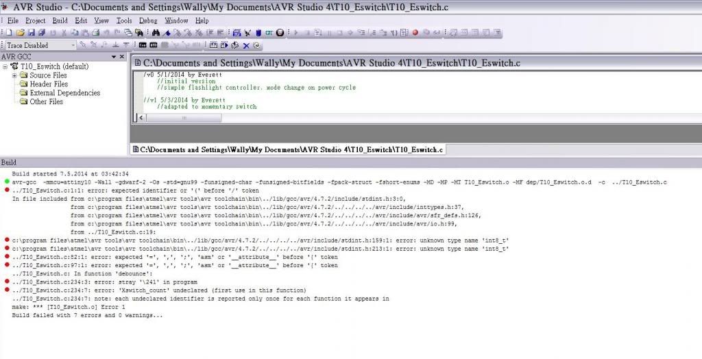
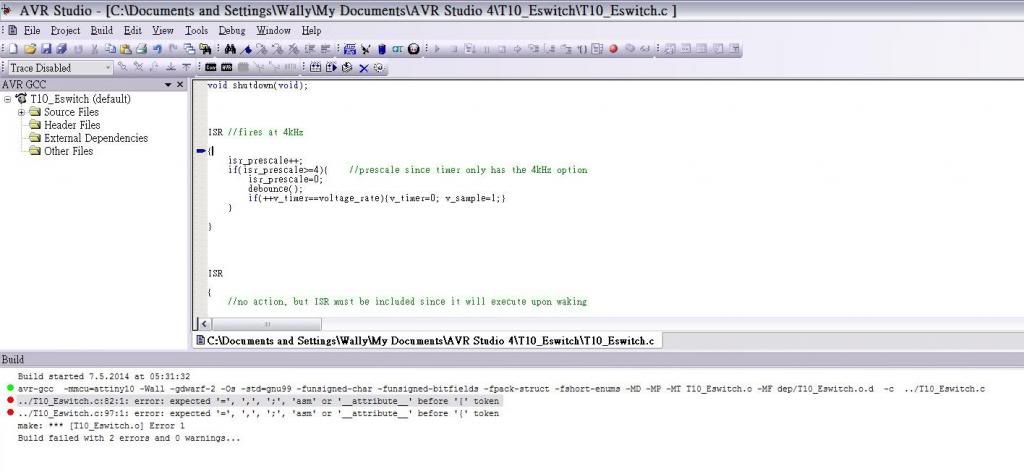
At the same time, I copied the code trying to build the hex file by AVRstudio 4.18 SP3 with avr8-gnu-toolchain-3.4.3.1072 which showed 7 errors and failed to build.
Is it the problem of the Amtel’s software?
I knew that the support of the C code for attiny10 is very poor.
Go through each one and look at the line it’s referring to. I can’t see what’s in your source file, but the error should be descriptive enough for you to figure out what’s wrong. For example, one says “Xswitch_count” is undefined, it looks like an X was added to the variable that I named switch_count. Go look at that line and see what happened, then fix the name by removing the “X”
That code uses 60% of the flash? It’s 1024 bytes of flash, right?
I may have to use a bigger chip for the mods I have planned… or at least fight with it for quite a while to try to fit everything into the 1024 bytes on an attiny13a. It’ll be like the old days, trying to fit everything into a single segment of RAM under DOS.
Regarding the V mon of the firmware, I would like to ask:
because attiny10 doesn’t have an internal reference voltage. the V mon is carried out by Vcc level monitoring function of the chip. So voltage divider is not needed anymore and also the V mon is meaningless if the power supply to the chip through a voltage regulator.
The line ” if(read_voltage()<100){ //set threshold for external voltage here ” The 100 here is represent VLM3 (Triggering sets the VLM Flag (VLMF) and generates a VLM interrupt, if enabled ), not a value of the voltage level.
Yeah but you noticed in the old days coding was ALOT cleaner because the designers had to be methodical in design…they HAD to make it do what they needed to do with minimal space…now with huge RAM space and this and that…they got sloppy and the result is bloat…
But I’m not a coder…so I could be WAAAAAY off, but I remember OS’s fitting on 1CD vs a DVD and such
Heck I liked using a Linux OS called DSL [Damn Small Linux] (based on Debian) that ran off of 50mb image
No, coding wasn’t cleaner in the old days. It wasn’t really more of anything, really, aside from generally more low-level. Bigger and better hardware has given us more ways to shoot ourselves in the foot, but it has also allowed for more expressive power to make cleaner, better code.
Older code frequently had to do terrible things in the name of efficiency. A clean design might not be able to run, so they’d use craptastic designs or approximations which could execute smaller or faster.
Old Linux distros were fun, but I had already had my fill of do-it-yourself before Damn Small Linux was created. I started long enough ago that most distros were basically just a boot floppy and then you had to DIY the rest.
It’ll be fun trying to fit what I want into 1024 bytes… but if it gets too frustrating, I don’t mind replacing it with something roomier. Mostly, I just need time to get started; too many days turn into 14-hour shifts.
The implementation I showed just measures the voltage on PB2, compared to Vcc. There are no associated interrupts. The number 100 was just a placeholder so you could put in whatever level you want. This method would work without the internal reference if the mcu is powered by a zener diode or similar arrangement where Vcc isn’t dependent on battery voltage, and you would connect PB2 to battery through a divider.
I have to ask, if you wanted the voltage monitor by internal reference, why didn’t you just stick with the PIC10F322 in my original example and avoid all this trouble?
The story is that Dr. Jones posted the MiniDrv firmware here which I though that is great to port it from attiny13a to this little guy attiny10. However, I studied a lot of materials about the attiny10 have found that it is quite different from the attiny13a and not popular in C programming. I have given up but when I read your post of PIC10F322, I though I should ask for your professional comments. Sorry for my poor english and bad expression, my questions are what my understanding to the code. If it is wrong, please educate me.
Same question for how can I change the threshold for attiny10, for the PIC10F322, I can change the line 64 ’ if(read_voltage()>87){ ’ . and I know the value 87 come from. But for attiny10, I don’t know how to change it.
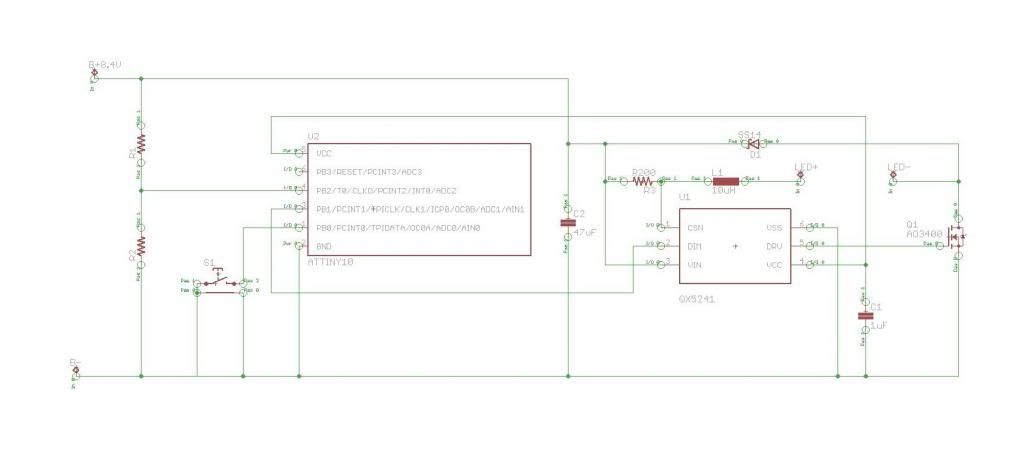
The driver which I supposed to build is a 2 LI-ion cells buck driver. The Vcc of the attiny10 is supplied from the 5V voltage regulator of the driver IC. The protection circuit of the battery pack will cut off the power supply at 6.2V. So, if I can set the Vmon force down the light level from High to Med at about 6.4-6.5V will be prefect. If it requires a voltage divider, please teach me how to calculate the ratio of the R1 and R2.
No need to apologize about your English, it is very good. The ratio of R1 and R2 can be anything that will limit the voltage applied to PB2 to less than your Vcc of 5V. The voltage that the ADC measures will be an 8-bit number representing the ratio of voltage on PB2 to Vcc: ADC = Vin/Vcc*255, or with Vcc=5 the equation simplifies to ADC = Vin*51. To get the best resolution, we want the divider to use the full range of 0-5V, so we want 5V to correspond to maximum battery voltage of 8.4V. Therefore the ratio needs to be 5/8.4, or 0.6. This is the ratio of the center voltage to the top voltage, which is R2/(R1+R2). The resistor values can add up to anything as long as they have this ratio. To avoid extra drain on the battery, we want the total value of the divider to be very high, maybe around 100kOhms (which will draw a maximum of 84uA). From there, we have R1+R2=100k and R2/100k = 0.6, so R2=60k and R1=40k. Your threshold value will then be 6.5V * 0.6 * 51 = 199.
I have some concerns about sleep mode with your design. Do you know what the standby current of the QX5241 is if the DIM pin is held low? It may be very high, especially if it is continuing to run the 5V regulator. I think you might want to consider adding a power switch and removing the off mode from the software
I concur that may be a problem I should use power cycle instead of tactile switch. The standby current of the QX5241 is 210uA. I expect including the attiny in idle mode will not exceeding 325uA (210+85+30=325). A pack of 2xUR16500F(1600mAh) battery will last for 205 days. I am greedy if you can also post the code for power cycle. :bigsmile:
One more question, the code seems to be descending mode. My driver is for a head lamp which I don’t want to lose my night vision. Can I just simply change the mode number to modify it to ascending mode.
enum mode{
off=0,
low=1,
med=2,
max=3,
};