(this will be a limited post for now because I am going away until next wednesday, I will update this post with graphs and such when I have time again)
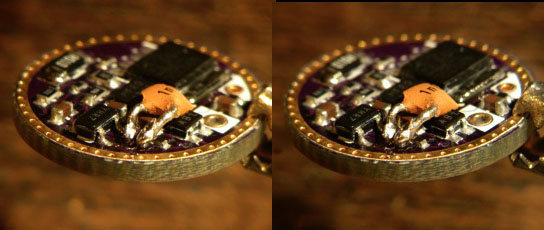
I received led4powers driver in the mail last week and today I had some time for testing. In a PM led4power asked me to change a cap for a different value because preliminary results from HKJ showed oscillations of some kind at certain circumstances. No idea what it was exactly (I know Ohm's law quite well, and not much more than that), but I was to swap the smallest component on the board :sick: . and my local electronics shop did of course not have that small SMD cap so this is the first thing I did to this beautiful driver  (in stereo glory):
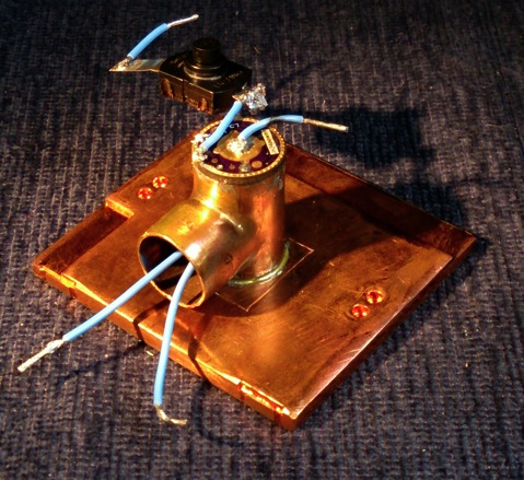
So far for the nice thin driver :-D . Next I made a cooling mount (copper sock soldered on copper plate) for the driver because it was not supposed to live in air because the overtemperature protection would not work properly then. I soldered the led-wires to the driver and then I soldered the driver on top of the mount:
The driver was going to be coupled to my power supply, with a reverse clicky in the circuit. The current entering the driver was measured by the power supply, the driver's entering voltage was measured direct at the driver pads, the driver drove the XM-L2 T6 3C dedomed led from my last test (see for the output of that led my XP-L test thread). The current through the led was measured by a 0.01Ohm sense resistor coupled to a voltmeter, the output of the led was measured in my integrating sphere.
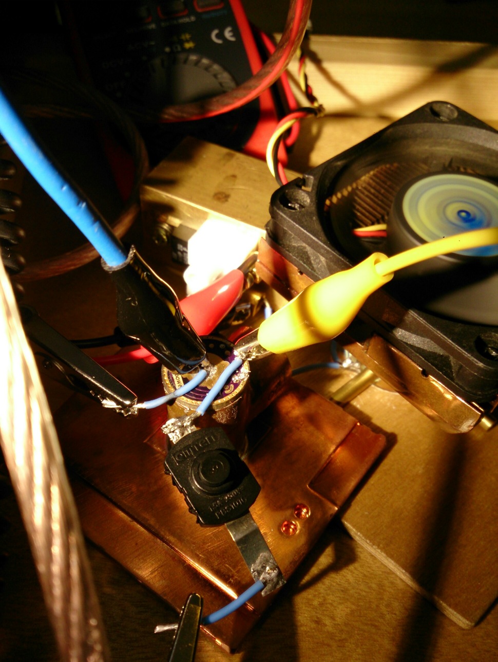
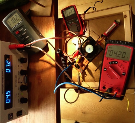
Here's the set-up just before the led mount was put into the sphere (my big DMM is measuring entrance current in this picture, but I needed it for volt measurements so I took it out of the circuit again and relied on the PS current reading with one digit less). The brass block next to the driver mount has the current sense resistor fixed on top.

Here is how it all looks during the testing, with the led sticking into the integrating sphere. You are looking here at the TURBO-test (moon2 engaged) with 4.2V driver entrance voltage (large DMM), 7.2A driver entrance current (on power supply), 7.33A led-current (small DMM, I converted mV to A) and (converted from 1182 luxvalue in photo) 1868 lumen led output (so the led output is exactly as last time I measured it :-) ). Of course no li-ion can keep 4.2V at 7.2A, so this situation is quite theoretical for a flashlight. See the numbers below for lower, more realistic voltages.
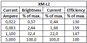
I am not so much into user interfaces so I did not test all the features of this driver, I leave that to others. Give me four modes with good spacing and I am a happy camper :-). So the test I did was applying various entrance voltages to the driver (impersonating the various states a single li-ion battery can be in), and see what the driver does to a XM-L2 at the four available modes and on TURBO. Maybe later I will test it on a XP-G2, but that will be a few weeks from now.
So here I should provide you with all sorts of nice graphs, but that is where I do not have the time for today, so I just present you with the raw data for now and wish you good luck cracking my handwriting and abbreviations :-D . I tested the high setting at many voltages, and the other settings at just a few voltages.
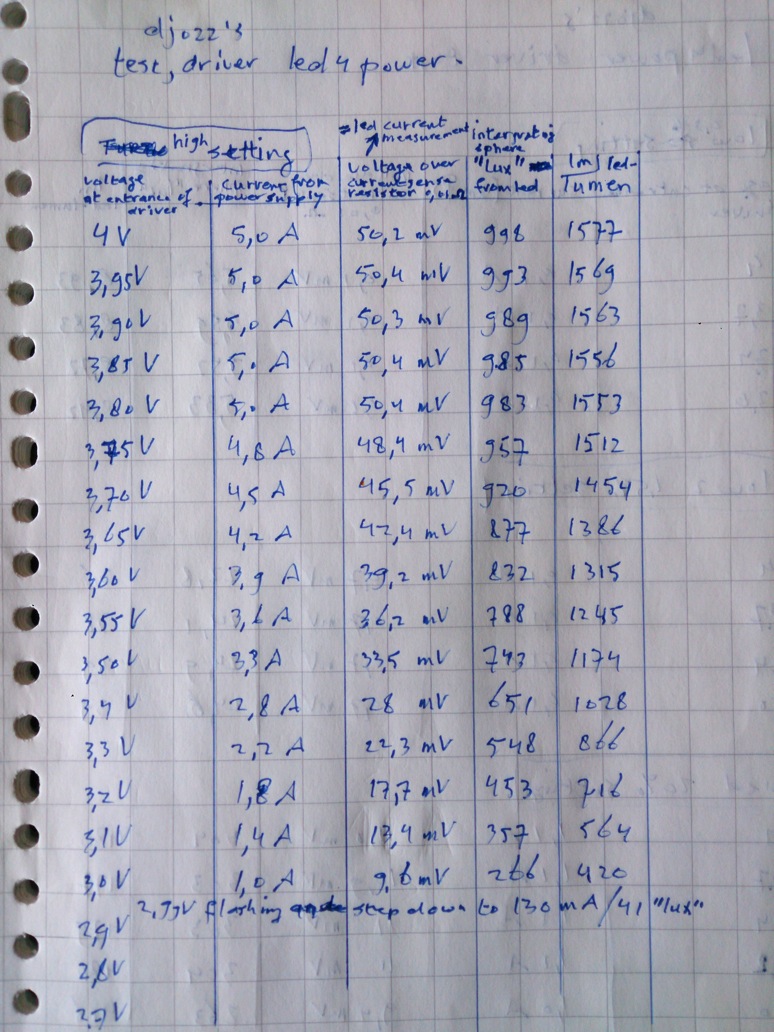
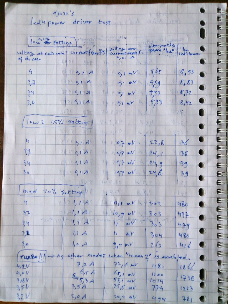
If you have interpreted the data well, you can decipher that this driver does what it promises, I think it is a great driver!
For who needs explanations/graphs/conclusions going with the numbers above, it will not be before next week before I can make and post them :-( (and perhaps even later, I am going camping with the family for two weeks next friday :-) ) .
That's al for now, I hope that you find it a useful test.