My lab setup
My testing lab is based on a lot of measuring equipment connected to computers, this way I can make most tests automatic. To make it easier to make test setups I have made a lot of different stuff to help with the tests.
In this article I will show some of the equipment I uses and how I have distributed it as test stations.
Test Equipment
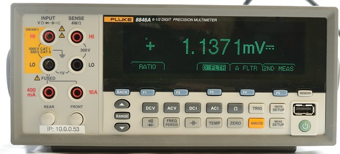
For many test I need a precise DMM, my preferred meters are benchtop meters. The ones I have a very precise and is powered from the mains (Mains powered is a big advantage when running tests for weeks).
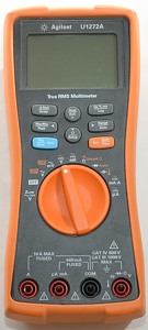
But I do not have enough of them and supplements with some handheld DMM’s with computer connection.
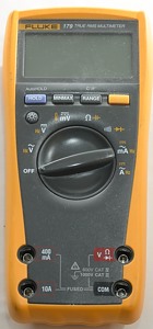
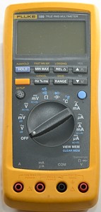
When measuring without a computer connection it is often the Fluke 179 I uses.
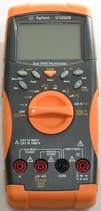
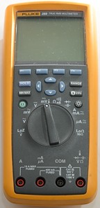
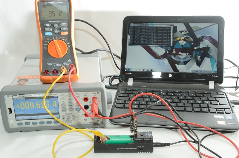
This DMM is often used like the Fluke and Agilent, but it has some extra features that means I uses it for a few extra measurements. It only has one current terminal, that can automatic switch from uA to A range, i.e. there is no risk of a blown fuse in the meter, if a charger goes from standby with uA to full charge with 1 or 2 ampere. This makes it my favorite meter to measure current.
It can also measure power including mains power (That was the reason I brought the meter), from uW to kW. This makes it possible to measure power usage of mains power supplies, both standby power and power when active.
Here I have used it to measure mains power, this makes it possible to calculate efficiency in a usb power supply
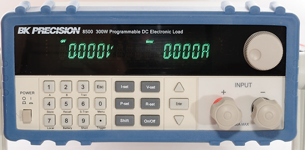
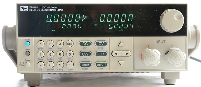
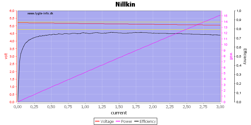
For battery test and other test where I need to draw some current I often uses electronic loads. They can be controlled from a computer and programmed to load with any current up to 30A. They can also load with power, resistance or fixed voltage. They both measure current and voltage with fairly good accuracy and can use 4 terminal measurement to eliminate errors from wires and connections.
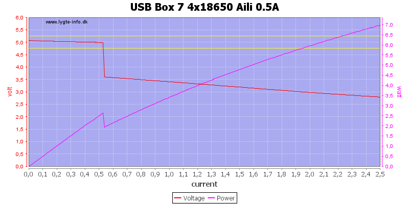
In the above curve I slowly increase current while measuring voltage. This is very easy to do with a electronic load.
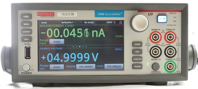
This SMU (Source measure unit) combines a DMM, a power supply and a electronic load in one meter. It cannot do the same as a DMM, but there is some overlap. The general idea while using a SMU is that you ask the smu to provide a current or voltage and then you measure current or voltage. I.e. if you want to measure ohms you can ask the SMU to provide 1mA and then measure the voltage (The SMU can do the calculation to ohm). Or for measuring current you ask it to provide 0 volt and then read the current. The burden voltage will be VERY low, as long as the current is within the SMU’s capability.
Mostly this type of meters is used to test components, because they can automatic and fast do a sweep for different currents/voltages.
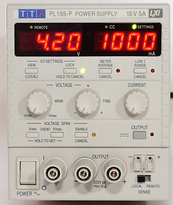
For battery test I also need some power source to charge batteries, I uses a lab power supply that is controlled from a computer. This supply can be programmed to a voltage and a current, making it easy to simulate a battery charger.
When controlled from a computer it is possible for the computer to read voltage and current from the power supply.
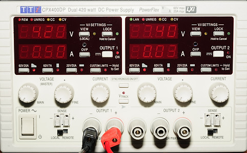
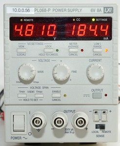
On my main test station I uses a large power supply, this can supply more than enough current for just about anything I work with.
This supply can also be controlled from a computer.
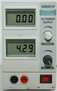
When I has to manually adjust the voltage, the above power supplies are not very good (Except if I program them). This small cheap supply is my favorite for manually adjustment, but to get that I have modified it. The voltage adjustment potmeter has been replaced with a multiturn potmeter. This makes it fairly easy to adjust with 0.01 volt resolution.
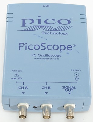
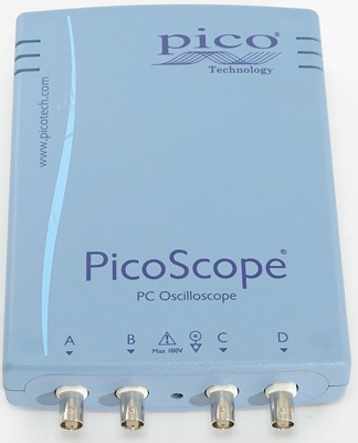
When checking how chargers or led drivers works I often uses a oscilloscope. It can easily show what is happening with a resolution better than 0.0000001 second (0.1us).
These need a computer for screen and handling, this works very well for me, because I need the measurements on the computer. One problem with a computer is noise, to avoid that I often uses a laptop computer to control these scopes.
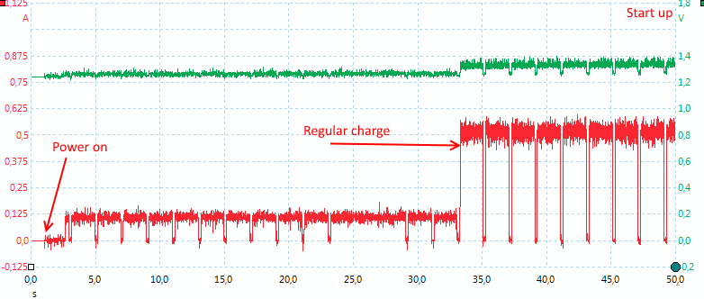
An oscilloscope trace of a charger that is starting.
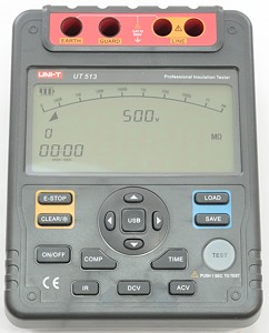
When testing mains connected devices I uses this meter to test the isolation between the mains and the low voltage side of the device. This will not tell me if the device follows all safety standards, but if it passes this test it might be safe.
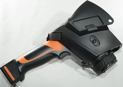
With devices that get hot I can use this IR camera to check it and see exactly where it gets hot and how hot it gets.
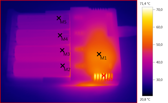
Above is a picture of a charger, taken with the IR camera.
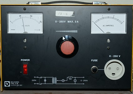
A isolation and vario trafo in one unit. Output voltage can be regulated from 0 to 250 V AC. This keeps me isolated from the mains, even if I am testing a device with bad isolation. It does also make it possible for me to perform test at 120 V AC.
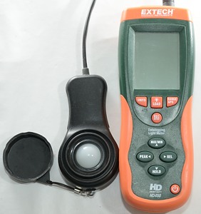
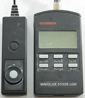
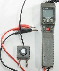
Working with flashlights and leds I do also use some lux meters. Two of the above meters can be connected to a computer, the last one has a DC voltage output, that can be connected to a DMM.
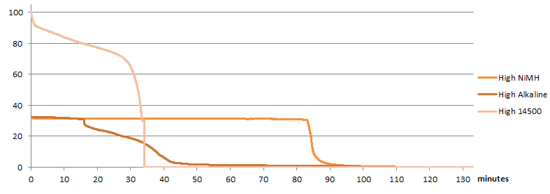
A runtime test of a flashlight (Note: I do not review flashlights at the current time).
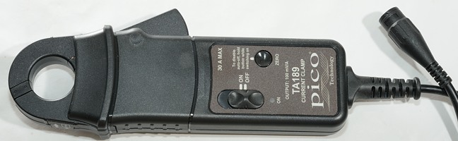
Often I uses small resistors to measure current because it is practical in my setup, but sometimes this clamp is more practical. It is designed for fairly low current (for a clamp) and requires a oscilloscope for readout.
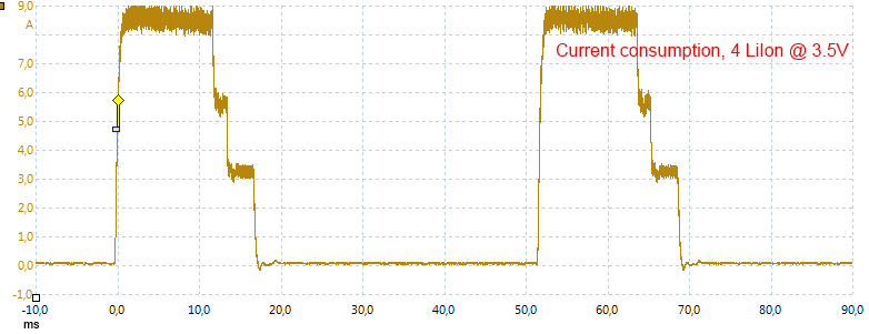
Here I am using the clamp to measure the current consumption of a pulsing charger.
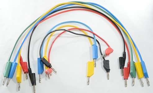
When connecting stuff I need a pile of test cables in all lengths. These cables exist in different qualities, when I need current through a cable I usual uses cables rated for 32A, for DMM connections the thinner cables are sufficient. Note: The 32A cables are only for low voltage.
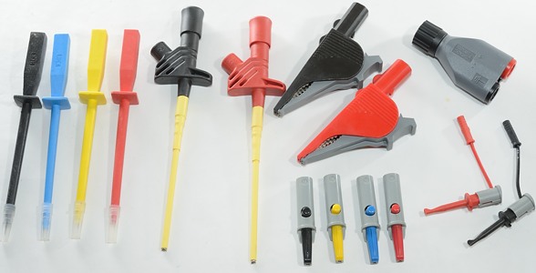
And I do also need ways to connect the test cables to devices.
Home made equipment
Here is some of my home made equipment, in the articles on how I test some specific device I may show some more.
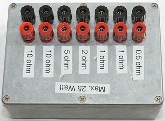
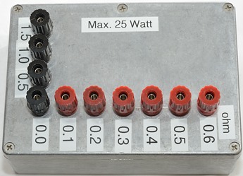
The electronic loads are useful for many things, but sometimes a regular resistor is more practical. To make it easy to connect I have made a couple of resistor boxes. With the first box I can connect resistors in series/parallel, depending on what I need.
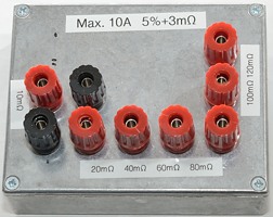
The second box is for lower resistance and external series/parallel connections would add to much resistance, instead I have connected all resistors in series inside the box.
These two boxes use 25W and 50W resistors, but due to the limited cooling the box provides they can only handle 25W total without cooling and while staying at safe temperatures.
I have also made a box for checking chargers that can measure battery resistance. I connect this box in series with a battery and by moving between the different resistances I can see if the charger display jumps with the same amount.
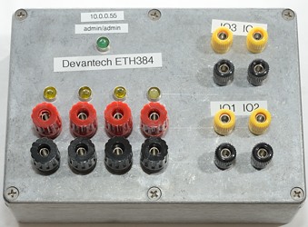
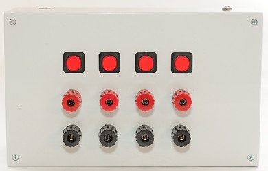
When testing batteries I need to switch between charging and discharging. To isolate the battery completely from the charger/power supply I uses a relay box between the charger and the battery. This relay box is also controlled from the computer.
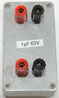
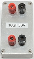
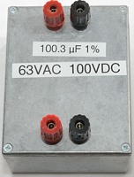
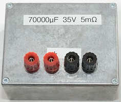
My power supplies does not always like pulse loading (PWM and strobe), to compensate for this I have made a capacitor box (The 70000uF), it is used in parallel with the power supply. The 1uF is often used as connection point when testing drivers.
All capacitor boxes use very thick connections internally, to keep the resistance down. The dual set of binding posts are done to keep the inductance from the capacitor to the wire low and also to make it easier to connect the box.
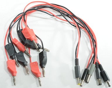
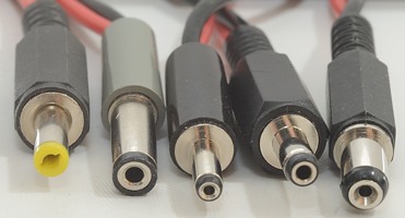
For checking stuff with a DC connector I have made a couple of cables with DC connector to banana plugs, I have plugs in 5 different sizes.
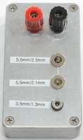
Sometimes I need a connection the other way with the DC plug.
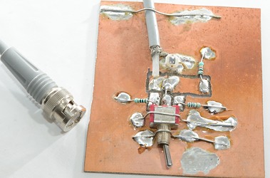
This is a photo diode with a parallel resistor, I uses it together with my oscilloscope. The switch is used to select between different resistors, a small value resistor makes it possible to record very fast flashes (Like 30kHz pwm), a larger resistor gives more signal
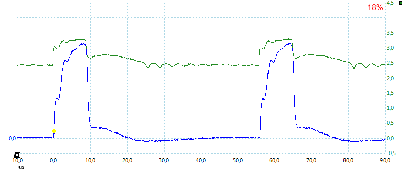
This photo diode is used to capture the blue trace in the above curve from my oscilloscope.
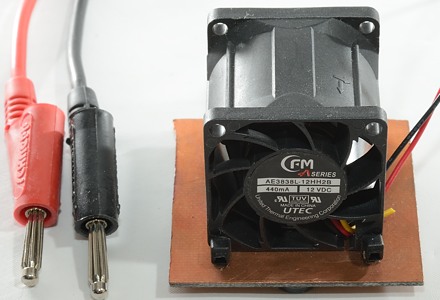
When testing drivers I often need some cooling. This small fan is running very fast, giving a fast airflow, this works very well for cooling a driver (But the noise is bad).
Other
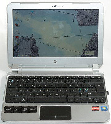
Each test station needs a computer. Except for the main station, all the computers are laptops. The equipment is connected either with usb or with wired network.
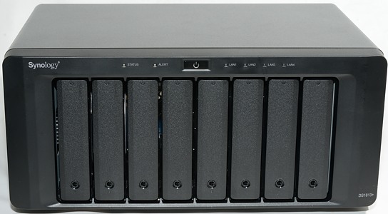
With all the testing work I do, I am a bit worried about dead harddisks and computer crashes. Most of my data is daily duplicated to this NAS server that is running a RAID 6 configuration.
I have also been using external usb harddisks for backup, but I do not make backup frequently enough that way. The automatic backup is much better, then I only have to verify that my recent files are on the backup once in a while.
Test stations
I am using what I call test stations for the different testing jobs. Each station contains a computer and a couple of instruments. At the current time I have five and they are often all busy. On test station 1 to 4 I only run tests that takes hours or longer, all short tests are run on main.
First version of test station 3 testing a charger.
Main testing station
This is my main computer, that is uses for all my writing. It has access to all types of testing equipment and can do any test (Except battery), but I prefer to not run very long tests on it.
This is used for chargers, power banks, drivers and other stuff. When I do manually tests it is always done on this test station. This means that anything I test (Except batteries), needs some time on this station.
This station consist of a computer, a 50A power supply, a small power supply, a bench multimeter, three DMM’s, an electronic load, a oscilloscope, a lux meter and some other equipment as needed.
Test station 1
My oldest battery test station, it was started in December 2011. It is used to test 18650 lithium Ion batteries of 2800mAh or more and all 26xxx lithium Ion batteries.
This station consist of a computer, a power supply, a relay box and an electronic load.
Test station 2
It was started a few months later and is used for smaller LiIon batteries (i.e. below 2800mAh) and primary batteries.
This station consist of a computer, a power supply, a relay box and a electronic load.
Test station 3
It was started at the beginning of 2014 and started as a charger test station, but has been expanded to handle batteries. I have moved all my NiMH battery tests to this station. I will use this for both NiMH batteries, chargers and power banks.
This station consists of a computer, a power supply, a bench multimeter, two DMM’s, a relay box and an electronic load.
Test station 4
From mid 2014, this station uses a high precision four quadrant power supply and DMM (Also called SMU). It can work with very low currents, but is limited to a maximum current of 1A. I do not plan to use this station much for reviews, but more for special projects. It can be used to do precision tests on batteries.
This station consist of a computer and the SMU.
Other
Not everything is done at test stations. Photo is done in a separate setup, that is also used for charger IR photos. Other IR photos are usual done at the main test station, because I need equipment to supply power and load.
The 5000 volt test is also done well away from all other equipment and wires.
How do I test
Here is a list of articles with more detailed description of test setups and equipment used.
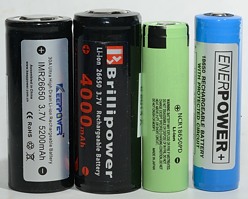
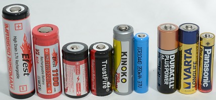
Batteries.
Chargers
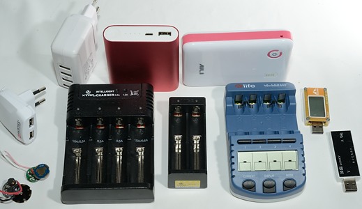
USB power chargers and power banks
Flashlight led driver circuits
Note: Equipment will not always be as shown, I do frequently update/supplement my equipment.
wow.
Lots of awesome equipment!
Pfff thats a whole lot, must cost a fortune!
Thanks for sharing
Impressive! 8)
Wow very cool to see the the equipment that produces the results we all rely on. I googled a few of them and the Velleman PS1503SBU is the only thing I can afford! :bigsmile:
Insane equipment, I’m surprised you don’t have a full scale bench oscilloscope! (But I’m sure you do, haha.)
So amazing!
Remember that the standard Velleman does not have a multiturn voltage control. This makes it difficult to adjust the voltage precisely .
Not anymore, the usb scopes does a very good job. I might get one again, but it does not have very high priority.
Amazing HKJ, I love precision equipment.
Is this a red Mi Power Bank 10,4Ah? Do/Did you test it?
The picture for “Main testing station ” is not correct I think.
“This is my main computer…” There is no computer in the picture.
And why aren’t you showing the actual testation for each one (1-5) instead of showing batteries?
Thank you so much for this, I’ve been wanting to know more about your setup for a long time. Your work is invaluable to us all.
Are you spending all that time and money just as a hobby? Are you doing this at home? Do you plan to work in battery testing/manufacturing any time soon?
I do not know if it is called Mi, but it is 10.4Ah. I have tested it but not published a review yet.
 Computers are boring to look at. I have selected to show what it is used for.
Wow! Very, very nice! 8)
I assume you also use all that equipment for your work, what is your line of work when not in BLF? If you don’t mind me asking…
The one I have is from Gearbest.
At the current time: No.
I have done a lot of electronic development, but at the current time it is software development I do.
Some nice kit! I like the photodiode solution for fast PWM.
I am impressed! I see you take a large effort to get all equipment as precise and calibrated as possible, that must give very accurate results and also a lot of ease of mind. I understand that very well, I always have to ask myself what I am measuring is real or caused by the limited equipment and method I use, and I do not always find out :-( (but will always post my doubts). Unfortunately I can not afford to spend a lot on my stuff.
Thanks for this impressive tour d'equipment :-)
“A isolation and vario trafo in one unit.” - what model/brand is that?
That's where it's so good that you're very open about your equipment and testing methods. Since I don't have the fancy equipment or the depth of skills HKJ has, I'm probably the biggest critic of my test results. At some point I'd like to get a dc power supply, dc load and an oscilloscope, but that's going to take some time. Even then, my ability to test and correct calibration will be very limited or nonexistent.
Precise equipment is no guarantee for accurate measurement, but only one of the required conditions. It is also important to know how to do measurements.
Calibration is another chapter. I do not send my equipment to calibration, it is way to expensive.
Instead I verify it against each other and some "standards" I have.
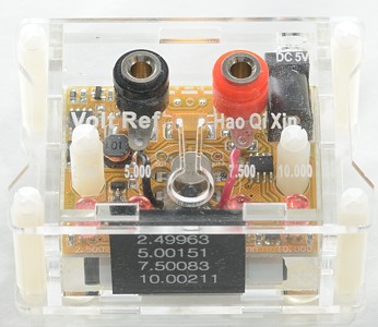
This box is one of my voltage references.
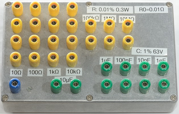
For resistance I made my own box. When using the 6½ digits meters on these resistors they must show: 0.9999xx or 1.0000xx and they all do.
I do not know. I am not going to check its backside. It is rather heavy to move around and it is not placed for easy movement.
I bought it used some years ago.
I know B&O made one many years ago and I would have preferred to get one of them, but found the above one first.