Custom automotive LED DRL --- updated with installed pictures

I decided to try my hand at something other than LED flashlights...


I bought a new (used) car recently which did not come equipped with a set of OEM LED DRL’s that are becoming mainstream these days. So what to do? Put my flashlight skills to work and come up with a custom solution.

Pictured are some of the components used to assembled this DIY LED DRL. A complete list is below.

Parts list

The plan was to use 8 x Nichia 119 for each DRL wired in parallel with the two sets wired in series (2s8p). The Flexblock can supply a maximum of 2A, so each LED would be getting 250mA. I did some initial bench testing and found this would be plenty of output to be visible without blinding oncoming traffic. I could always throttle the output back using the wired pot if needed.

Reflowing the emitters was done on a hot plate. The boards need to be sanded down slightly to fit inside the aluminum U-channel. I also needed to electrically isolate the center solder pad with kapton tape as the Nichia 119 + and - pads would overlap causing a short.


Testing each after reflow


The DRL housing was constructed from aluminum U-channel cut to size. The end caps were made from aluminum flat bar stock cut and secured with JB Weld. After reflowing onto the boards, 8 emitters were secured to a piece of aluminum flat bar with arctic paste and soldering in parallel. The emitter “strip” could now be slid down into the DRL housing. The fit was nice and snug. Additional thermal paste was used between the emitter strip and aluminum housing. Wire holes were drilled out the back side.


DRL housing


Test fit with emitters before wiring

Emitters mounted onto aluminum flat bar and wired in parallel


The “reflector” was fabricated out of the same aluminum flat bar. Holes were drilled to match the spacing of the emitters. They were made slightly larger than the emitter dome, and flared out at the top. To prevent shorting, Kapton tape was added to the bottom side which sits flush against the emitters.

The main components complete


Both sets assembled


Some initial bench testing.


Room lights off. Running at low power.


Room lights on running at ~1A


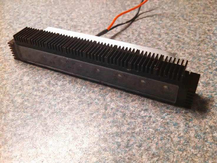
Even running at ~250mA/emitter, the DRLs got warm after a short while so required some additional heatsinking. A heat sink was cut from a piece salvaged from an old battery backup and glued to the back side of the DRL. Additionally, smaller 14x14 heatsink squares were attached to the top and sides.


Heat sink for the back


Cutting off a piece was no easy task


Test fit with wires fed through


The heat sink was attached using both arctic adhesive (in the middle) for heat transfer, and JB Weld along the perimeter for extra strength.


Since the heatsink fins on the backside would not catch much air passing through, I also mounted smaller heatsinks along the top and sides to improve cooling.


Final assembly and painted black.


The last thing was to install the plexiglass front cover. Since this was designed as a press fit (very tight), I had to make sure everything was right since it would be nearly impossible to remove.


Final product ready to mount.


That's it for now.


Next post will have the install onto my car and some photos of it in action.

I'm no mechanic or electrical wizard so mounting and wiring the DRLs took some serious planning and inspection of the engine bay/interior fuse box. There were two fuse boxes I could potential tap power from, one inside the engine bay near the battery, and the other on the drivers side inside the car. Since I wanted to have access to the dimming feature via the attached potentiometer, I ended up tapping power from inside the car.

I wanted the DRLs to come on/off with the ignition, so I tested several fuse positions with a voltmeter to find one that worked that way. To tap power, I used a fuse tap purchased from the local autoparts store. For the LED positive and negative leads I chose 18G automotive wire which was inserted into plastic automotive conduit and wrapped with electrical tape for water resistance. Leads were passed through the engine firewall and snaked to the front of the vehicle.

The DRLs were mounted onto the lower front grill using existing threaded screw holes on the heatsinks. There was very little clearance to work with, so to create screw holes in the plastic grill, I had to use a soldering iron to "melt" them. It was not the cleanest job, but it worked and would be hidden once the DRLs were mounted.

Instead of using washers on the underside, I secured the DRLs with a strip of plexiglass that had matching holes drilled in. That way, if the grill became cracked, the DRLs would still be securely fastened.

Picture of fuse box with mounted Buckblock. I attached a heat sink to the top since it became warm after running for >15 min. The external pot is hanging out as I have not decided where I want to mount it yet.

Testing DRLs prior to mounting

Close up of the installed DRLs


Both DRLs

Pot on lowest setting

Pot on highest setting (2A)

From a distance. Headlights, foglights and DRLs on

Overall, I am pleased with how this project turned out. I've been running these for about 6 weeks with no issue.

That’s awesome man I love your work. Any idea how the total cost is going to compare to ready-made equivalent?

Can you tell me more about the driver and where you got it? I’d like to hotrod my reverse lights but don’t know how to drive them. I’m thinking a triple XP-L for about 3k Lumens… Being reverse lights are only on for 30 seconds at most it’ll be great!

Cost was about $60.

There are many off the shelf DRL's that can be purchased. Many (most) are crap. I think one of the best are these, but they are not cheap and I don't think they are as bright as mine, nor can the be independently controlled with a dimmer.

Specs on the driver are here.

Made a mistake - I am using the BuckBlock, not FlexBlock. Correct the OP.

That's a lot of lumens for back up lights. You're sure you need that much?

Hahaha, we’re on BLF!!

Oh yeah, right (head smack!)

Updated Post #2

Nice work, cool mod and looks good too!

Well done!

Some people use them for tailgaters.

Too bad that DIY DRL cannot be used in Poland (and probably in entire Europe). DRL lights need to have proper homologation - ECE-R87 and ECE-R48.

Nice work, and looking good in the car!

Awesome mod, Hill! The only thing I'd have done differently is not paint the chamfered reflectors black. They aren't reflectors if they don't reflect. Before mounting the flat bar/reflector strip I'd have painted it first then hit the reflector holes with the same bit used to make them in the first place to strip the paint from them. Even still, your DLRs look awesome and work great!

Thanks everyone for the compliments! This was a very long term project and it's nice it turn out as I had hope!

[quote=leaftye]

Some people use them for tailgaters.

[/quote]

Yes - I have heard of that. A user on one of the automotive forums did exactly that, except he used a headlight bulb and wired it so he could switch it on manually (i.e. car did not need to be in reverse)

Thankfully, the US DOT regs regarding DRLs have not yet caught up with European standards (at least as far as I am aware). I don't need to have my car inspected until December and hopefully there will be no issues. I was recently pulled over for speeding and the officer said nothing about my DRLs. I tried to design them to look more like stock DRLs than some cheesy aftermarket ones.

Thanks Johnny! I hear what you are saying but as I saw it, these are not meant to throw light as much as be seen by oncoming motorists. I wanted to keep them as "stealthy" as possible, hence having the fronts painted black so they would be less conspicuous when the car was parked (I have a "black theme going - black paint, smoked tail lights, black rims - still need to tint the windows). I did not do any comparison of painting vs unpainted so cannot comment on the difference in output. My guess is that it would be only marginal.