First RGBW_clicky light is up and running! Video here
I'm making this thread to document the progress of the 17 and 20mm drivers that are for tterev3's MELD UI (his FW is proprietary but he's happy to sell programmed MCU's) .If you havent yet checked out what MELD is capable of I highly suggest you check out his blog for a demo of its amazing functionality.
*edit* there is now another 17mm driver with a different MCU and a FW for power cycle mode changes (no e-switch needed, just the tail clicky!!) in post 9, I will be building 5 identical RGBW Supfire A6's using these drivers with quad emitters and 5 X6's with XML colors, if you think you may be interested in purchasing one please let me know ASAP (2-3 A6's spoken for, one X6 spoken for).
These started out in my thread about my SL-3 RGB SST-90 built (which runs DrJones RGB FW and doesnt have a white channel, instead mixing RG and B for white). I've really gotten on a RGB kick recently, its as fun as lasers without the danger. If you dont have a RGB light you NEED one, they're really fun to play with and do actually give off white light even without a white emitter so its actually useful as a flashlight, not just a toy.
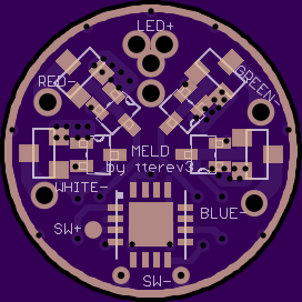
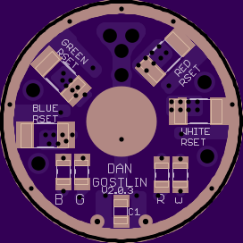
These are a pair of 17 and 20mm CC drivers, since we cant tune the PWM level in the FW I needed to find a way to control current per channel, the current can be set via the RSET resistors. When runnig a 2502 FET the max current would be 4.2A, with the AO3400 it would increase to 5.7A. *NOTE* max current on the 17mm version is limited by the power the 1206's can dissipate and will be around 2.5A per channel, the larger 20mm driver is being upgraded to the double size 2512's and will be able to do the full power of the FET's
Some people have tried to say the red emitter wont work cause of its lower vf but I have a RGB light running now at >6A (as well as a few other red only lights) and thats simply not the case, it runs fine and is even output with the other channels, it may technically overdrive the red channel but it doesnt negatively effect operation. This would also be a great driver for an XML-Color. Note the FW REQUIRES a e-switch, its not able to be modified to tail click only, there is just to much function for it to be controlled by power cycle. (see reply 9 for a power cycle controlled option)
These are going to be very voltage intensive circuits, as such I decided to leave polarity protection off cause of its v drop (also since the PIC MCU handles voltage monitoring internally even a slight drop over a protection diode would cause it to read a fair bit lower), I briefly considered a PFET for polarity protection but that would give the same issues. Again there is NO POLARITY PROTECTION on either of these drivers
[20mm version not happening]
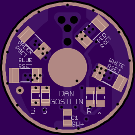
and shrunk down (was NOT easy) to 17mm:
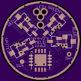
Here the SW+ has a trace to a masked over via, this is for if you are installing this piggyback and need to make connections from the bottom (if the SW+ connects from the top use the pad, if it connects from the bottom just scrape the mask from that via and connect there)
Both drivers can be piggybacked onto your host contact board or can be installed directly in the 17 or 20mm pills but again an e-switch is required, there is no way around this.
edited for spellin'