Review: Modified Ledoman 6x XM-L 3 Mode Bike Light "Ledoman X6"

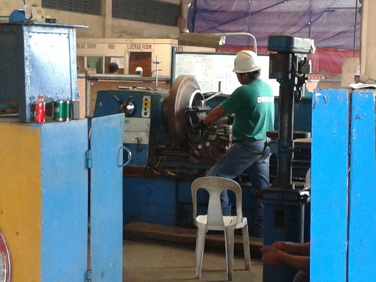
It took a while for the lathe work to begin. My friend, the machinist, has been busy all week working on the valve flanges of our steam pipelines.

So preparations were made for the Ledoman X6 while waiting.

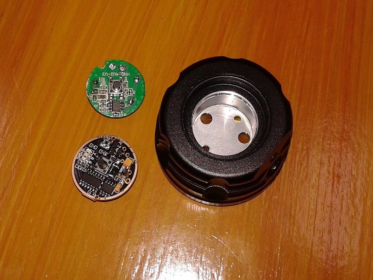
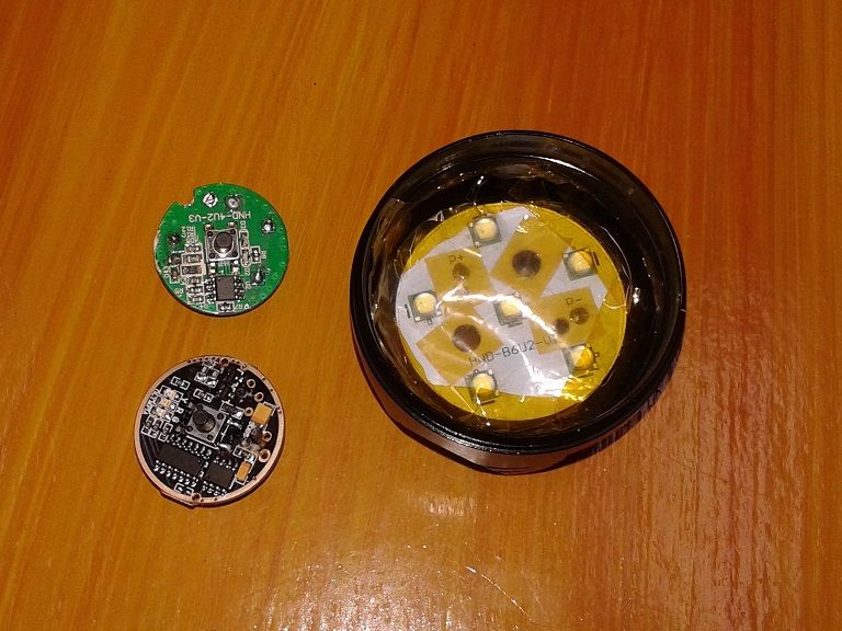
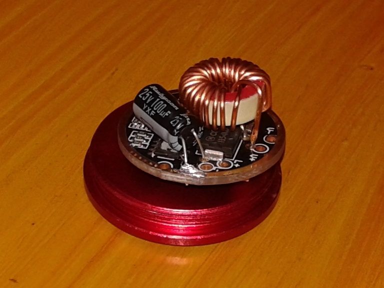
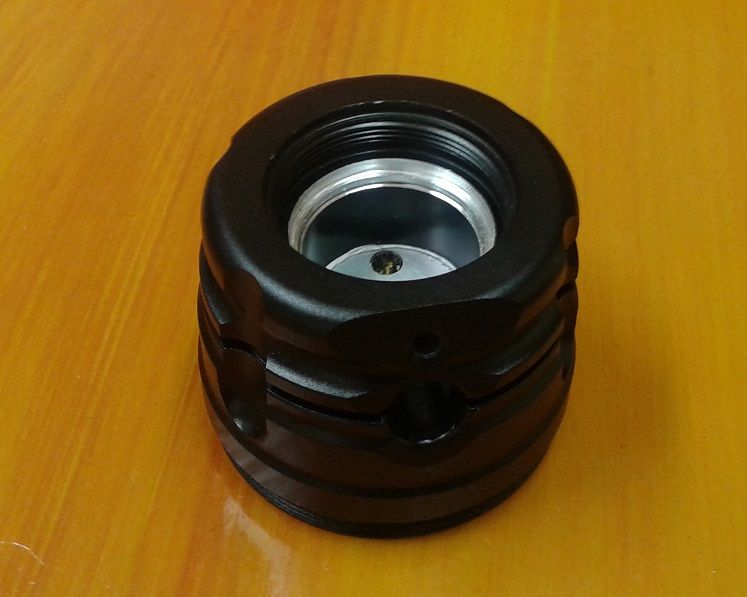
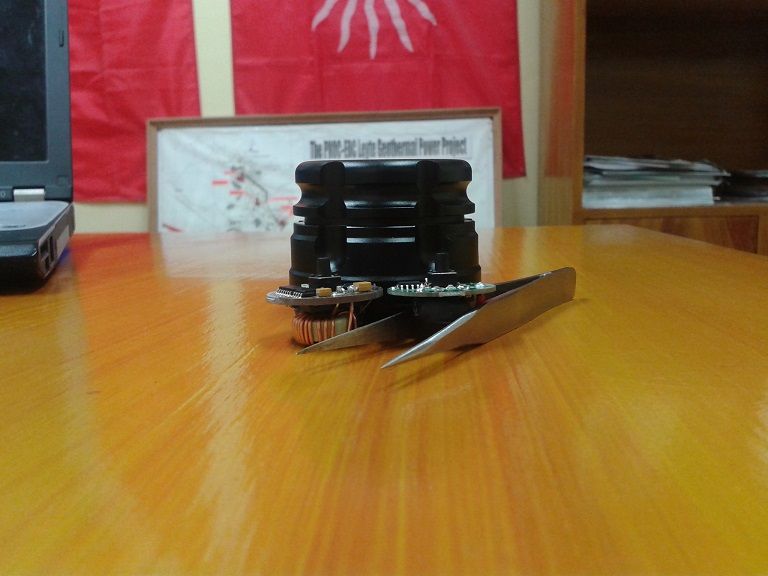
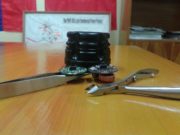
What I need to do is swap the old driver at the top with the DX driver at the bottom

However, I need to take care that the 6 XM-L LEDs won’t be destroyed in the process so they were covered with plastic and kapton tape.

Another minor problem was the solder blob near the leg of the capacitor which might hinder in fitting the driver perfectly.

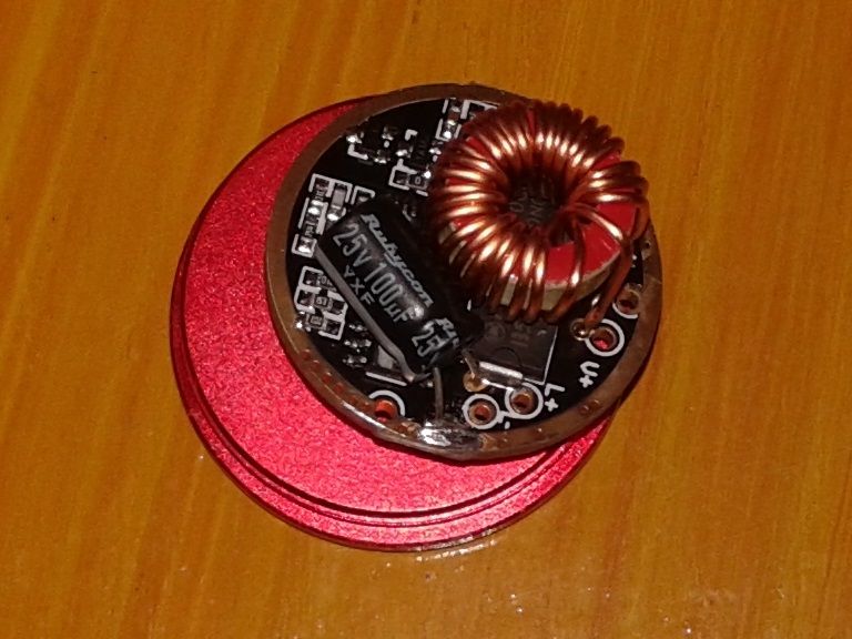
A little filing solved the problem

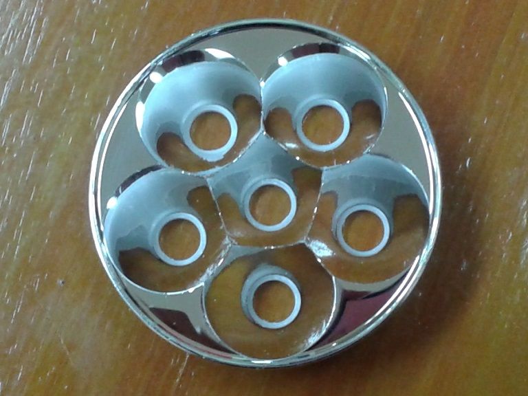
Another problem are the centering rings which are too long that it blocks part of the LED while inside the reflector

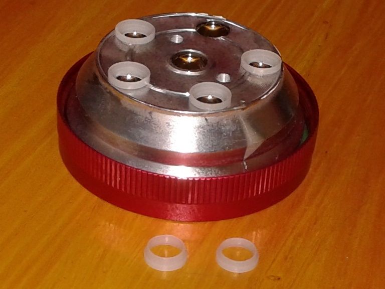
Some filing solved the problem. The centering ring at the left is stock and at the right is ‘filed’

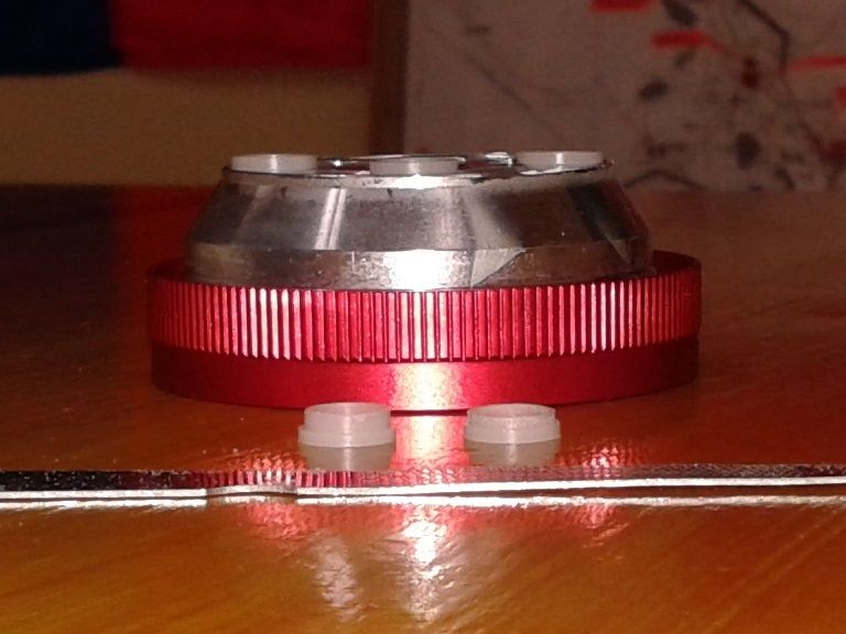
This is evident in this picture. The rightmost ring is filed while the rest are stock

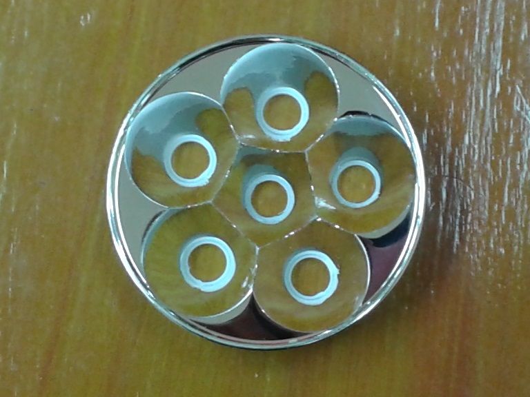
Here all rings are filed. Much better

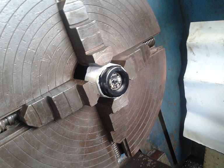
Finally the Lathe Machine became available yesterday, 24 Sept, so the Ledoman X6 was immediately prepared for lathe work

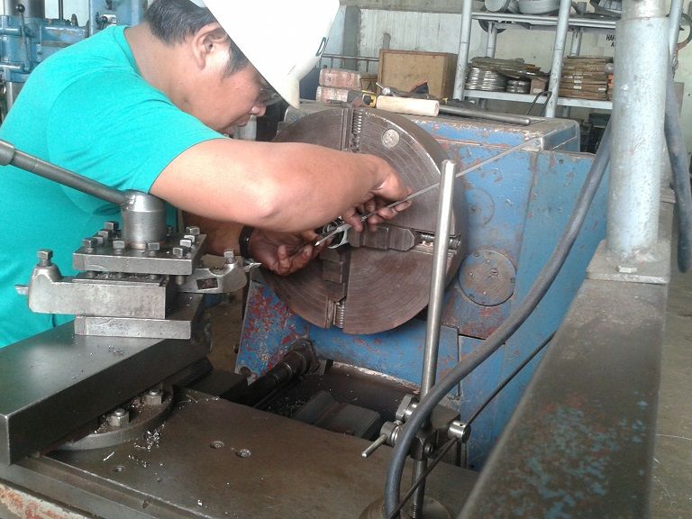
Then Lathe Work was started, finally

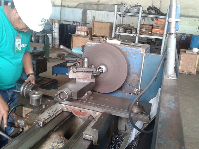
A closer view of the X6 while being machined by the lathe

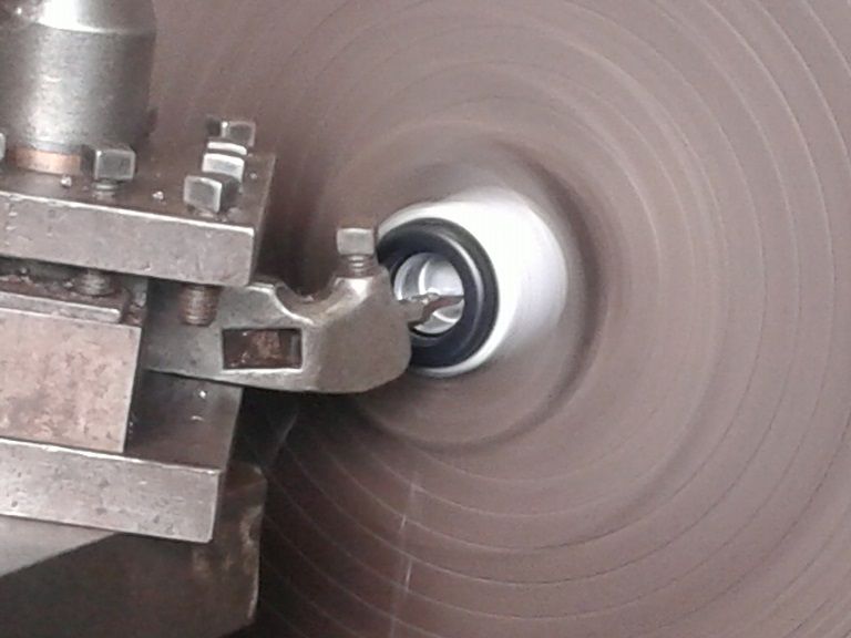
Until the DX Driver finally fitted perfectly

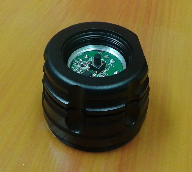
To ensure flexibility, the lathe work was designed that I can use the old driver as well as the new DX driver

The old driver still fits perfectly

And so can the new DX driver

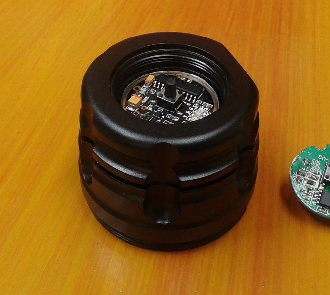
However, the PCB of the DX driver is thicker than the old driver, and it is positioned much closer to the tail cap. There could be a problem when the tail cap switch is emplaced.

To solve the problem, the plastic end of the DX switch was ‘nipped’

Finally its time to assemble the light with the DX driver. Yellow & blue AWG 22 were used for lead wires. The originals were red and black AWG 24. I tried using AWG 18 but they were too fat.

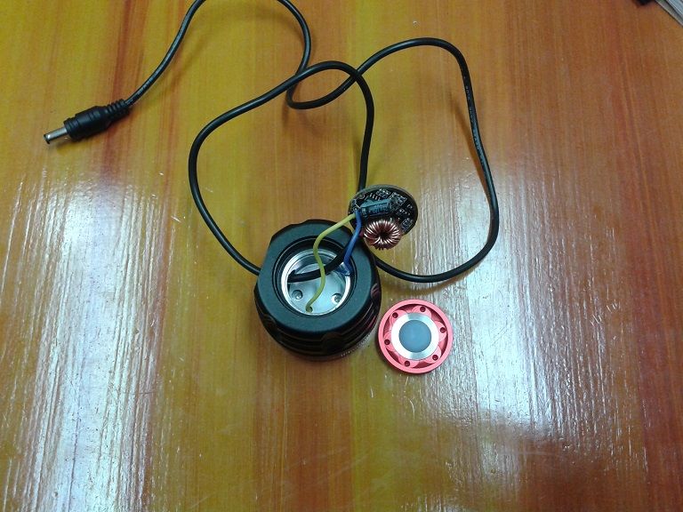
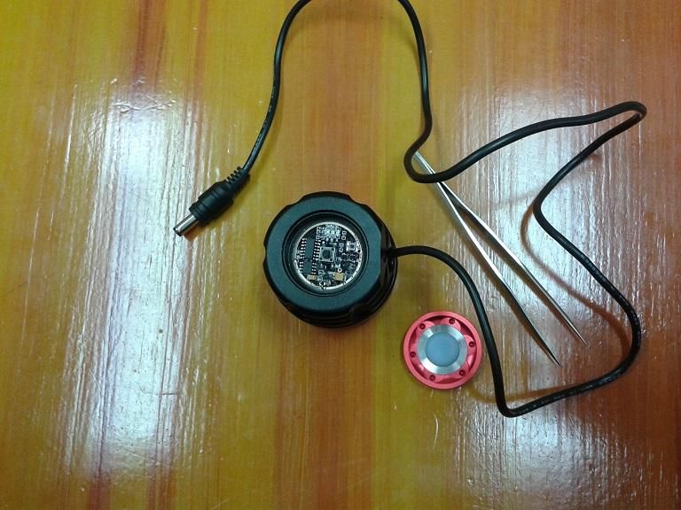
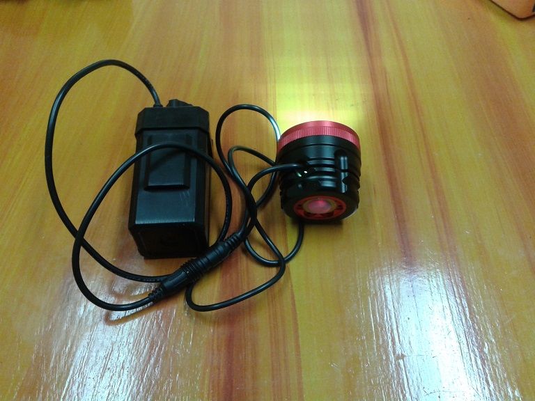
The DX driver is finally in place and ready for testing

I used my 2S2P battery case with 4 x Sanyo 2600 mAh 18650s. The tail cap lit green which means it was installed correctly

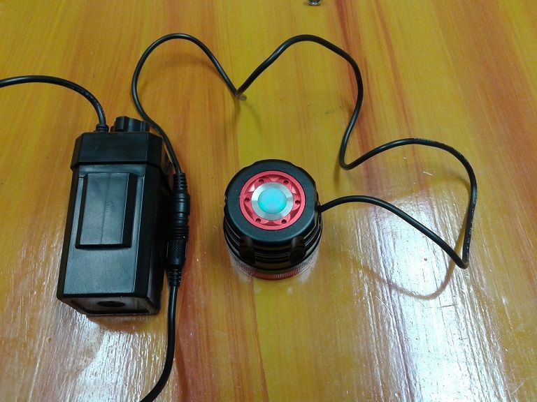
However when turned to high, the light immediately turns back to low and the tail cap turns red. 7.4 volts is not sufficient to power this driver for it to function properly

Its time to seek the help from this guy, my BTU Shocker

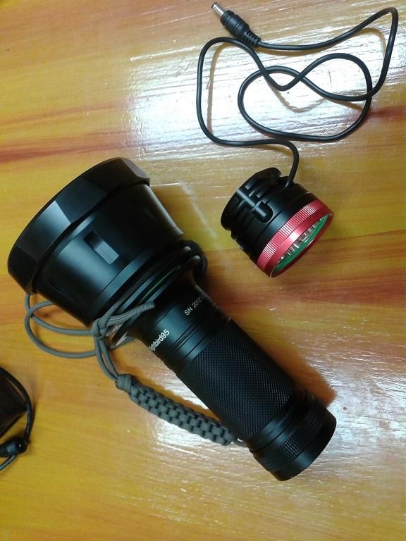
I used its 3S1P battery case containing 3 x Panasonic 3400 mAh 18650s. Clicking through all the levels seem to make this DX driver work well

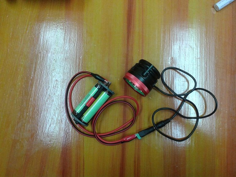
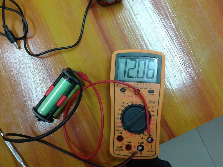
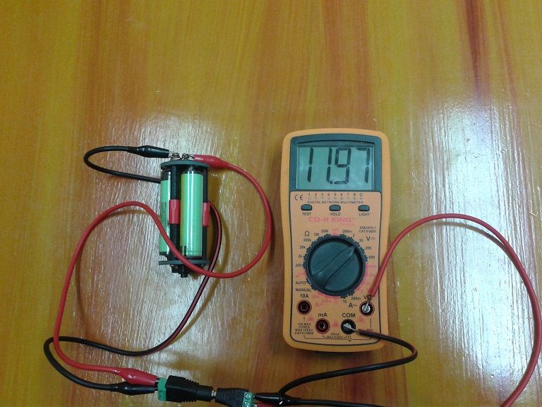
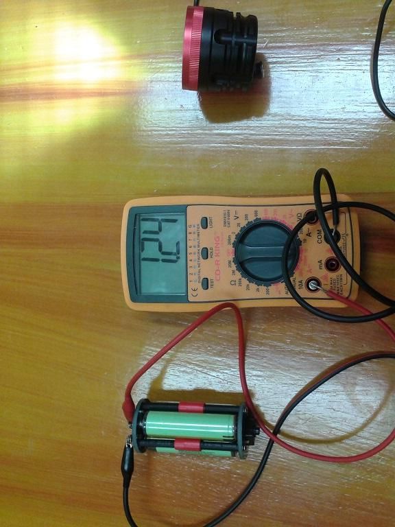
So I went ahead and started gathering data. The Shocker battery case produces 12.06 volts

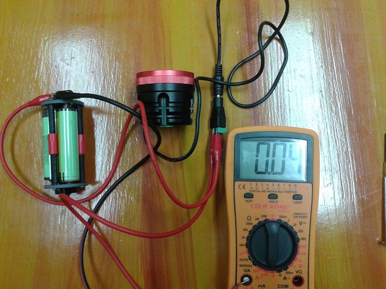
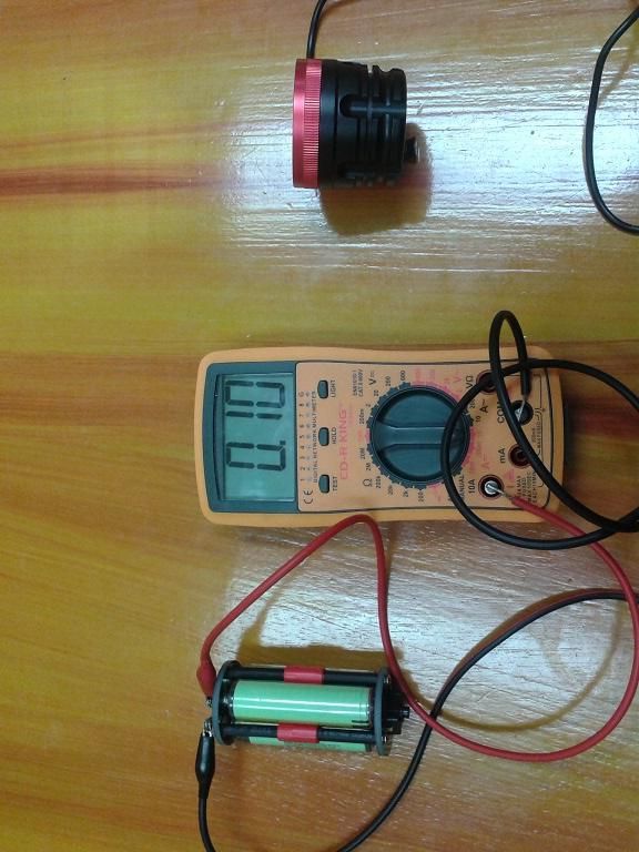
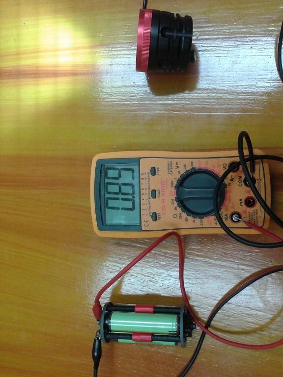
Next, I took the current readings. Even when turned off, it drains 40 mA

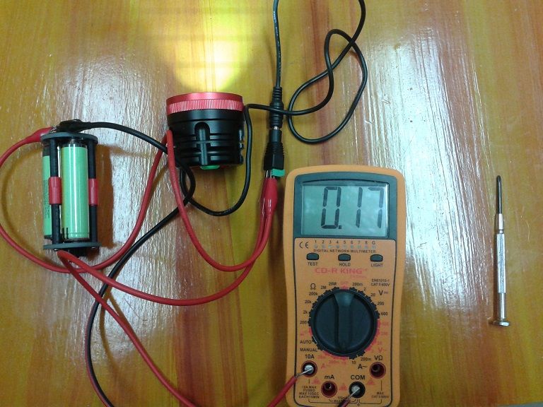
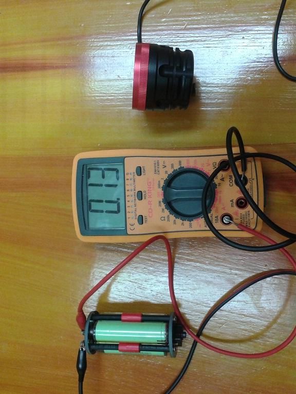
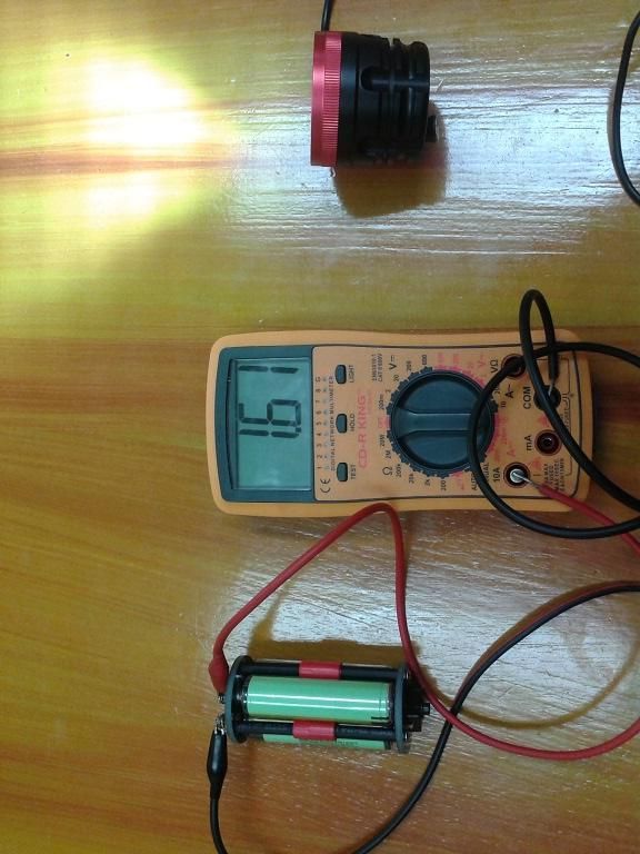
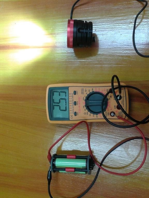
At low, it drains 170 mA from the power source
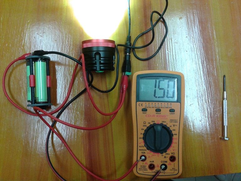
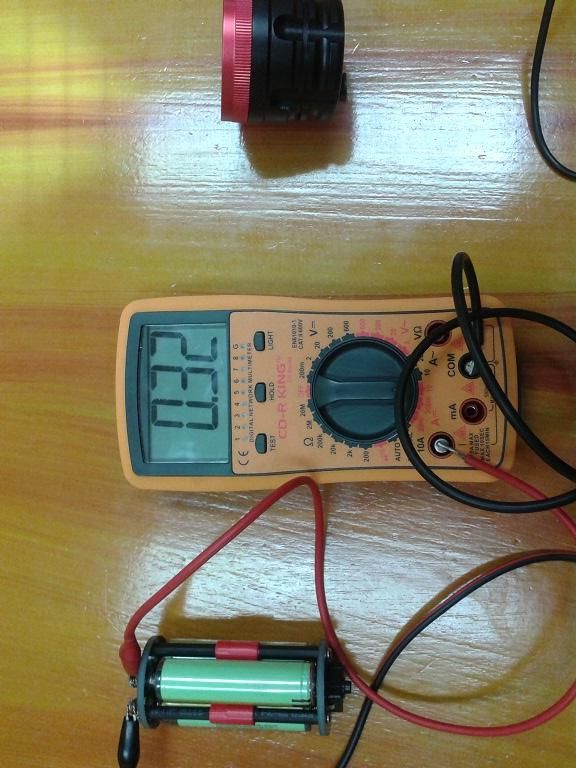
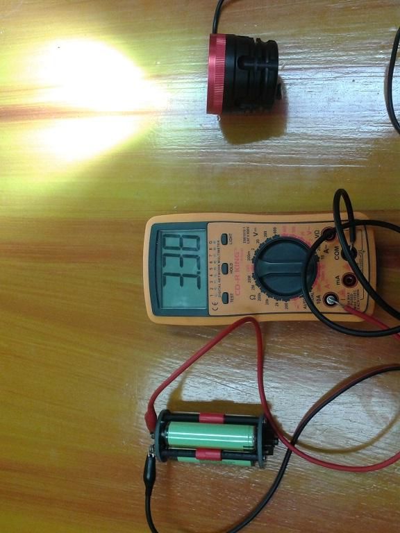
Mid draws 1500 mA

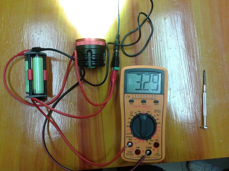
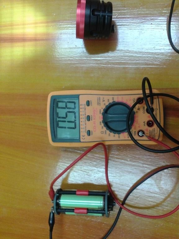
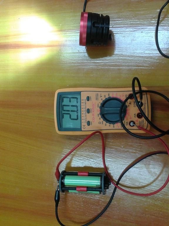
And high draws 3290 mA. Considering the 12.06 volts pumped by the Shocker battery case, that’s a total of 39.7 watts!

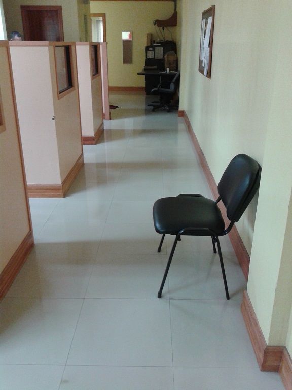
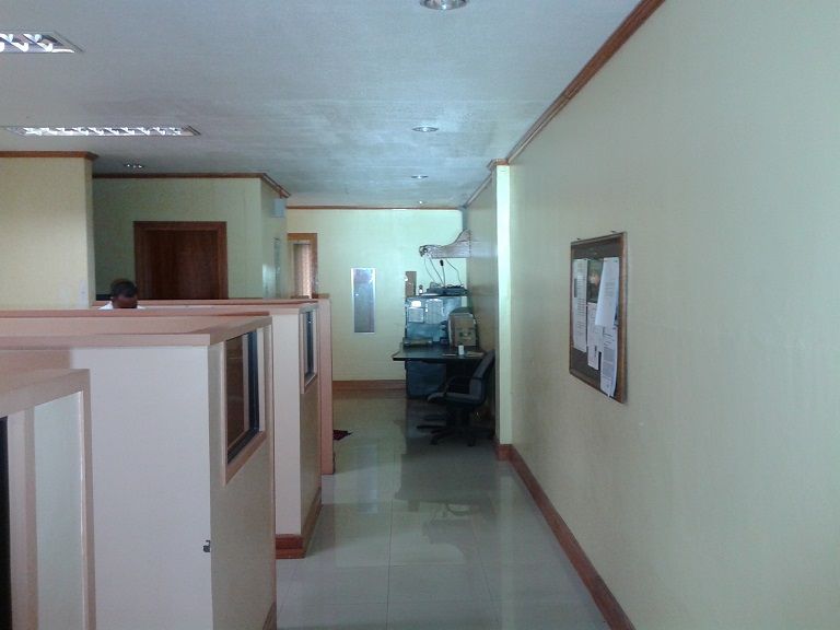
At about 40 watts, the Ledoman X6 should be a monster and I need to know its lux readings. The place where I take lux readings is at the hallway in my office. Its eleven (11) meters from the near corner of the column to the opposite wall.

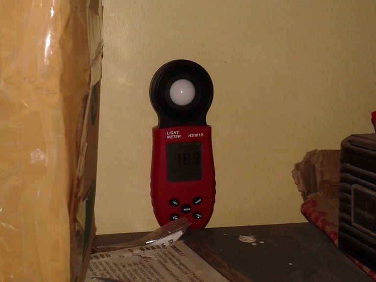
I simply placed the light at eye level and shine it directly to the HS1010 placed on top of the filing cabinet at the opposite wall, like this

At eleven meters, the reading is 189 lux (as compared to 66 lux with the stock). That would compute to 22.9 kcd (7.9 kcd with stock) or 329 meters throw (179 meters stock).

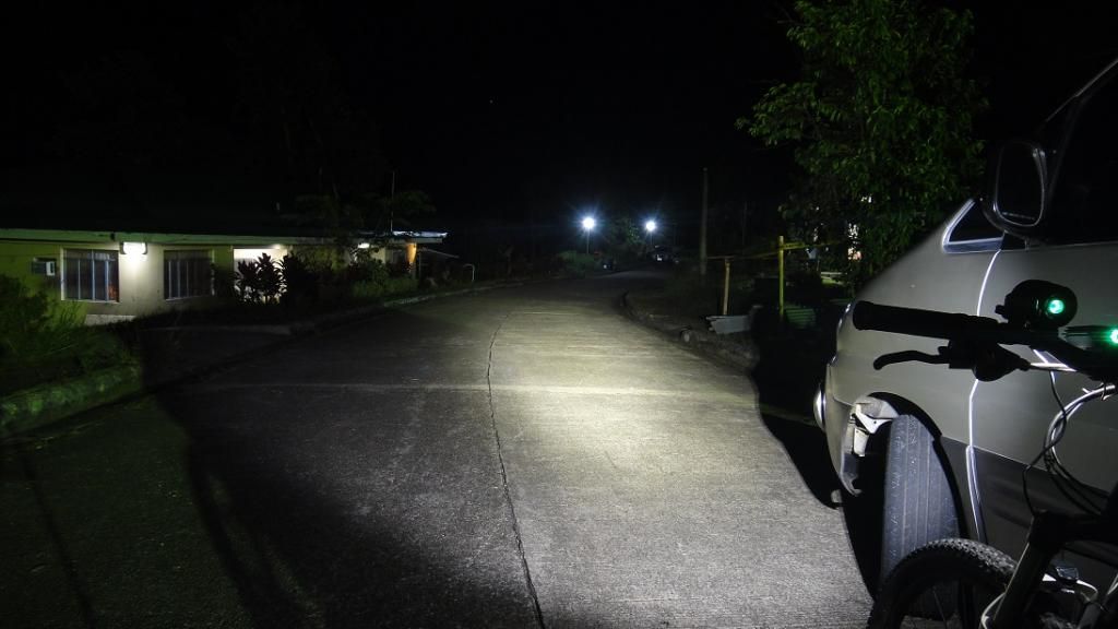
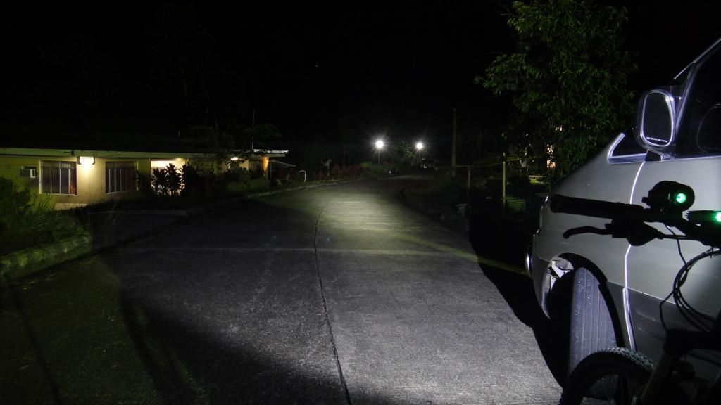
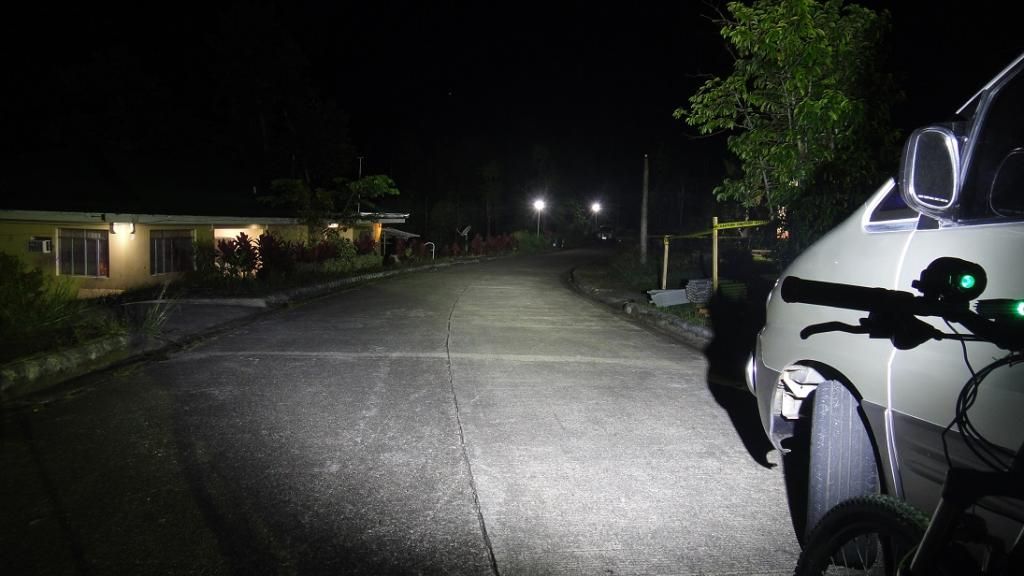
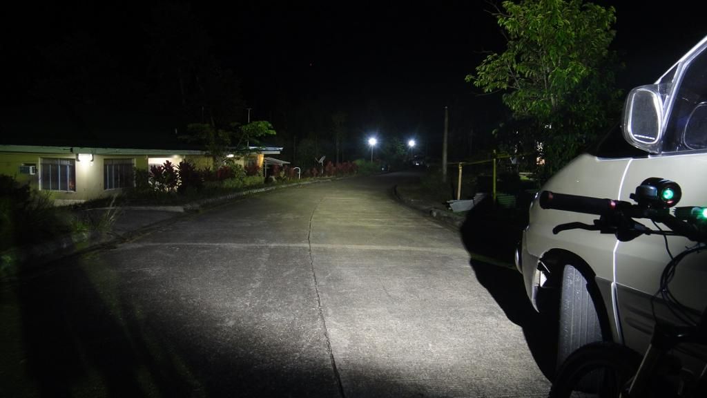
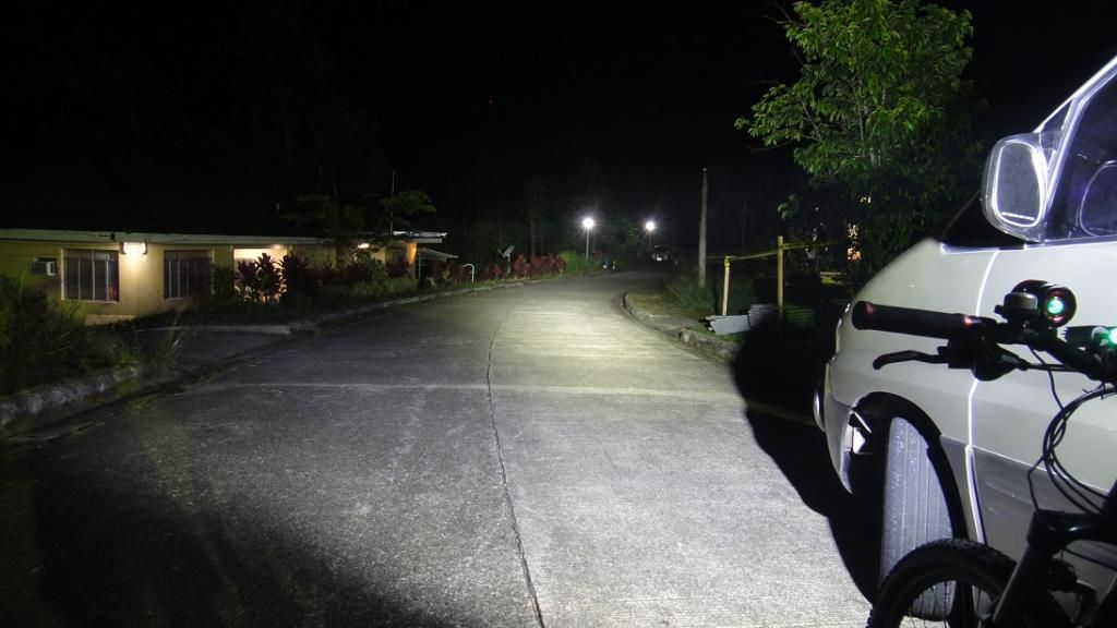
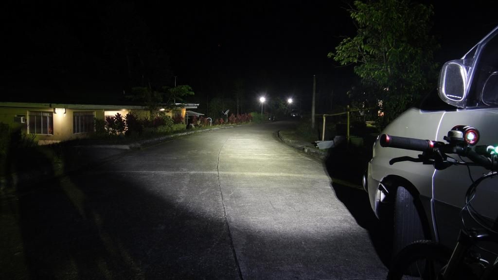
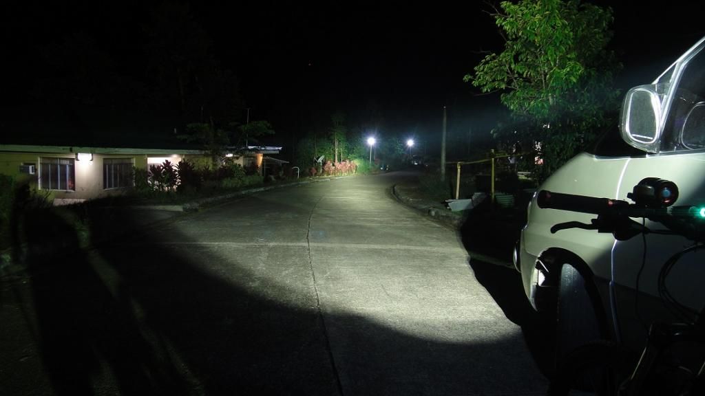
This modified Ledoman X6 is simply amazing and I think its would be about as bright as my TrustFire X100. The only problem would be the power supply because conventional 2S2P battery cases won’t make this light work to its full potential and i don’t think a 2S3P will make a difference either. I’ll be taking outside beam shots tonight to see for myself if this indeed is a little monster.

I finally finished taking the beam shots of this Ledoman X6 compared with my bike lights and other multi XML lights.

Here’s the SolarStorm X2 modified to 2x XM-L2 T6 3Bs on direct aluminum MCPCB, my Bike’s Low Beam

And the SingFire SF-90, my bike’s High Beam

Here’s the modified Ledoman X6. It completely beats the two bike lights

Now lets see how it fares with my other multi XM-L lights. Here’s my Sky Ray King modified to 3x XM-L2 T6 3Bs on SinkPads

My TrustFire X-100. Its flood is similar to the X6 but it has a more intense hot spot probably because of the slightly bigger reflectors and the much wider head diameter.

My Black Shadow Terminator. More of a thrower than a flooder.

And my BTU Shocker ’Nightbird95”, modified to 3x dedomed XM-L2 T6 1Bs on SinkPads. Yeah its not the same league with the Ledoman X6 but I just can’t resist showing it off. :bigsmile:

Over-all, I’m very happy with the outcome of the Ledoman X6 Mod. I’ll be seeking a 12 volt power source to power this thing up. I hope I can find a suitable 3S2P battery case for this.

Very nice work Nightbird95 all the way around. You really took that light up a couple levels. The light looked so small on your friends lathe. That thing looks like it is all serious business.

You may want to check for thermal sag on high with a fan running over the light just to make sure that mcpcb is up for the job.

Thanks ImA4Wheelr!

Yes I’ll try checking the thermal sag as suggested. The light indeed easily gets hot at high.

I’m also planning to convert its MCPCP into a direct thermal path using copper wire inserts to make the X6 handle heat much better.

Cool project! 40 watts of light! Wow! Are you intending this for a bike light or what?

-Garry

Hi. Where did you get the light from? (link please)

I want to show it off as a bike light but I’m not sure I need to do that. My X2 and SF90 combination already makes me the brightest bike at night in my town. Besides, I’m still looking for an appropriate power source for this as the common 2S2P battery packs won’t work. :~

Maybe this would make a good flood/search light for my car? :stuck_out_tongue:

That would be from this link.

I actually won it, complete with the DX driver, from ledoman’s giveaway thread hence named it the Ledoman X6. :bigsmile:

Excellent write-up. The right man certainly won this giveaway!

One question… how is the driver being secured in the housing?

Great job! I'm very happy for you and that you make it to work with the new driver. I hope you'll examine it's all settings - selecting from 10 intensity levels. Documenting currents/watage on all levels would be nice too. They should be somewhat linear except at the high end.

Mine driver does flickering at lover levels when powered by 3S2P pack. It might be different with 3S1S because of higher voltage drop. Have to try this to see the difference.

Need one small detail. How/where actualy did you trim those white center rings? What effect that has in a beam or brigtness?

Edit: figured out what you probably trim off.

I love your mod and what a fantastic read. Thanks for sharing. The machinist doesn't look to happy in the second picture and he must use that four jaw chuck on his lathe for everything he does. I'd hate to have to lift it of manually. Excellent effort.

Thanks NightSpy!

Just like the old driver, the new DX driver was press fit into the housing. That’s why we had to ensure during the lathe work that the inner diameter of the newly fabricated housing opening is exactly the same as the outer diameter of the DX driver.

Also the driver is not a perfect circle. There is a portion in the PCB where it was supposed to be connected to another PCB during manufacturing so you shouldn’t file/smoothen that up. You’ll need that to ensure that the driver will fit snugly to the housing. :slight_smile:

Thank you ledoman!

I’ll add the gathered data on the current/wattage readings of all levels in this review. I haven’t tried it yet since I spend most of my time last night setting up then resetting up my equipment at flashlights outside because of the on-and-off shower. That’s why a car was included in the pictures because it was used to secure/hide everything in case rain would suddenly fall. :~

For the centering rings, I simply used a nail file taken from my wife’s manicure set and it did the trick. It can be seen in the foreground in one of the pictures. Actually I also took a nail clipper from that set to nip the DX switch. :bigsmile:

Thanks MRsDNF!

Yes your observations are correct. He’s used to working on large and heavy flanges and the smallest he’s worked on, before working on this light, was 10 inches in diameter and weighing 5 kilograms. This is actually the smallest thing - and the most delicate - he’s worked on so far so he had to make a lot of fine adjustments before starting the Lathe Machine. :frowning:

Actually he told me afterwards that if it was somebody else who asked him to do this lathe work then he probably won’t. I guess its a good thing to have good friends wherever you go. :wink:

Nightbird95, no need to hurryy now. Take your time to discover it's features. Also note when something unusual happens ie. falling back to "safe" mode cause of temperature rise or voltage drop.

Last night I've put together mine 6x light and fix the driver into its final position. Flickering with 3S2P pack has almost gone. Trying before with 3S1P while driver was still hanging out still showed flickering. So it looks its good position of outer ring in the light is curing that.

It is obvious that it takes much more power from the batteries when powered with 3S2P pack comparing to 2S2P (or 2S3P). I'm wondering how long it can actualy run under so much power. I'm bit sceptical.

Tonight it is going on a ride with some other lights. Will try to take some pictures.

ledoman, got the data already! :wink:

Having used the battery case a lot during last night’s beam shots, its remaining voltage is only 11.97 volts.

Level 1 draws 100 mA from the battery pack. That’s equal to 1.2 watts

Level 2 draws 130 mA or equal to 1.6 watts

Level 3 draws 320 mA or 3.8 watts

Level 4 draws 580 mA or 6.9 watts

Level 5 draws 890 mA or 10.6 watts

Level 6 draws 1240 mA or 14.8 watts

Level 7 draws 1610 mA or 19.3 watts

Level 8 draws 2030 mA or 24.3 watts

Level 9 draws 2530 mA or 30.3 watts

And finally Level 10 draws 3380 mA or 40.5 watts

For my use, I set mode 1 to level 10, mode 2 to level 5, and mode 3 to level 1. :slight_smile:

Have you done watage calculation based on starting voltage? If so I find it wrong as when the current rise the voltage is dropping. You should read the voltage and current at the same moment. Then you'll get some lower power readings than those you published. If I'm wrong, take my apology.

We should put results in the table and/or graph for easy reading, but take it easy .

I see. :slight_smile:

The volt meter/amp meter from eBay that you recommended just arrived this afternoon. The problem is that I cant make it work. :~

This gadget should make it easier to get the actual voltage readings while the light is in use.

Where the heck is 40 watts of light throwing heat gonna go on that small head?

Better be riding pretty darn fast :stuck_out_tongue:

Either way, wicked cool mod, great job!