I suspected but I wasn’t sure… the AMC7135 has a self-recovering thermal fold-back circuit that drops the output to about 250ma in a solid step.
I was running 2x 7135’s on a brass strip opposite an XM-L. With the circuit was running at 700ma and with 4v input, it would fold back fairly quickly.
A simple touch with a finger on the 7135’s would cool them enough to recover almost immediately. A 3.6V input lowered the occurrence.
It was a DD setup with plus terminated to the gate pin at 4.0Vin.
I wanted to see if a 700ma micro-light would work. Too much heat when all the components share a small heat sink.
At fold-back, the 7135 would cool enough to recover the full output for about 10 seconds and go back into fold-back.
So the pair tolerated 500ma into an XM-L. At 3.6Vin, the cycle was much longer so the heat from the 7135’s was a significant contributor at the 4.0Vin (obviously).
This says that an XP-G2 at 350ma will work just fine and it is thermally protected. That’s the bright side of this experiment.
Does anyone know, how hot the 7135 chips could become? I want to stack a few 7135 chips (add 6 chips to one side of 8x 7135 driver) and use hot glue to make it more stable (my soldering skills aren't really good - it looks so easy, if oldlumens stack this little things. After soldering I want to use the glue). Do 7135 get hotter as 70 degree celsius (158 Fahrenheit).
The power that a 7135 dissipates is the excess voltage times the rating of the chip (350ma or 380ma). So if you are running a high power LED at max current, and you run a conventional cell which drops to under 4V when turned on, you might only be dropping less than 0.7V making the dissipation per device only about 0.25 watts. And as the voltage normalizes to 3.7V, the V-drop is even less.
I was running a full 2.8 watts in a small area (2x 7135 + XM-L at 700ma @ 4V) with no significant heat-sinking. The fold-back level was 2 watts and it self-recovered.
Its just a math thing but if you can provide a thermal path, it can’t hurt.
I use a little Arctic Silver Epoxy to hold the chips together. Just be sure not to short out the leads with that.
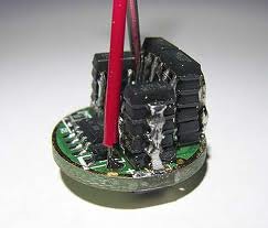
My guess is that most of the heat leaves the chip via the leads and not via the housing, so as long as the thick middle leads are well connected with enough solder, and the heat can go somewhere from there (via the outer ring to the pill) you're fine with stacking at any height (picture from Andi in 2011)
Yes, djozz has it right. Tie those tabs together. These are the best heat spreaders available. You can go as far as soldering a semi-cylinder around all those ground tabs. You can slit the cylinder to aid soldering.
Again, the more voltage you snub with the 7135’s, the more you need something special. In cases where you do a zener mod and your input voltage has a wider swing, this can be very useful. Just do the math up front to know what your dissipation ends up being. Also, if you are closely coupled to the heat from the emitter(s) in the pill, this could raise the ambient temperature around the driver. Remember that thermal dissipation is calculated as “rise above ambient” so if ambient is already hot, the chips will go up from that point by a constant delta (read: additive).
Anyone know how quickly it happens, when doing a zener mod? Depends on the overall output? Higher amp draws would actually help, because the batteries would sag quicker? and the led would be at a higher voltage the higher the amps were? MT-G2 at 9 amps would last longer on high than an MT-G2 at 3 amps? How long is "quickly" Anyone know for sure?
My guess is that it all depends on the environment. If they are completely independent from the emitter heat, they can tolerate ~1 watt per device in my test. Again, Vdrop * 0.35/0.38 will give you the wattage across the device. If you want some margin, shoot for no more than 3/4 watt per device with adequate heat-sinking of the pill directly to the body nearer to the emitter.
Since they are tolerant, it wouldn’t be hard to create a test setup.
That's a lot of stuff that will depend on a lot of other stuff.
Basically, I guess most of it would depend on which type of cells you want to use, which will depend on what you want it to do. If using plain ICR cells you're probably looking for regulated output and longer runtimes, so the ICR's greater voltage sag would make life easier for a 7135 driver. But for max output you'd use INR/IMR cells, which would be better suited to a FET driver. There's only a miniscule amount of waste heat with the sub-5milliohm FET, it's extremely efficient as long as the combo runs at an acceptable current.
High-drain low-sag INRs would probably not be best paired with a 3-4A 7135 driver. They'd just be fighting against each other.