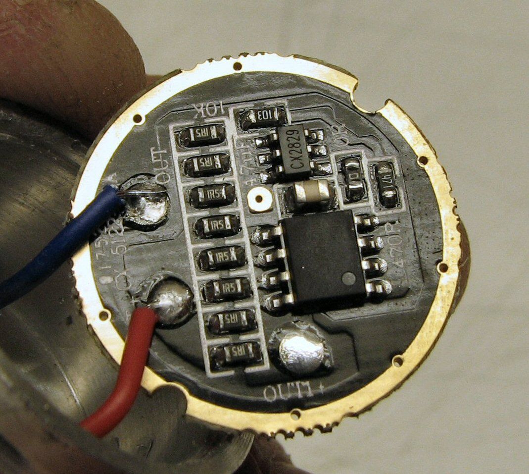
Hi All, i have recent brought a few of this Nanjg clone driver and i am wondering what is that 3 pin component circle in red in the picture does? its some kind of voltage regulator ? Any input would be greatly appreciated. ![]()

Hi All, i have recent brought a few of this Nanjg clone driver and i am wondering what is that 3 pin component circle in red in the picture does? its some kind of voltage regulator ? Any input would be greatly appreciated. ![]()
It's not a clone if it's using different components in a different circuit. That's just a driver using AMC7135s, nothing at all related to a Nanjg anything.
To figure it out you'll have to do the same work we did to reverse engineer the 105C. Is it worth it?
Would we be able to tell what is it from the code printed on the component? sorry for being a noob here… :bigsmile:
There is a chance, it would be easier if you could just follow the traces to it. My guess is a voltage regulator.
Strip all the parts off, then sand/file away the PCB masking so that all the traces are visible, since trying to check what's connected where with the parts still soldered in doesn't always work. Some of it will be obvious, but some possibly not, since some parts can be used in more than one way and might not always follow the recommended usage per the official datasheets. Correctly identifying the components isn't always enough.
The amount of work is only going to be worth it if you have a rather large pile of these oddball drivers... even then, if there isn't a large pool of other people using that same driver you'll be going it alone. There's no reason to use a functionally similar driver that is significantly different under the hood, when the original has already been reverse engineered nine ways from Sunday.
well, i dont think its worth the effort striping everything off and tracing the pcd and sort. I might as well stick to a well defined nanjg driver instead. ![]()
Looks good to me, why would you scrap without doing some detective work? That’s part of fun to me ![]() .
.
Look here: http://www.farnell.com/datasheets/578767.pdf
Is that a 2.7V voltage detector, it just might be! A hardware solution as opposed to the voltage divider analog input solution of the Nanjg 105C, very interesting.
The driver you pictured reminds me of a generic 8xAMC7135 driver from Fasttech.
The Fasttech one has a place for exactly that kind of package (first picture at 5-o-clock), but is unpopulated there. I have that driver here, the 3 traces lead to 1) Vin after diode, 2) gnd, 3) one pin of the MCU. Seems to be the same purpose.
Then maybe it’s for a low-voltage detector, like nickelflipper suggested?
Or maybe a FET, the 7135’s for lower modes, the FET for direct drive?
NM, CK. very interesting on the voltage detector
Replacement for the resistor divider?
alltoclear can you get us some better pics of the driver and possible part #’s?
If this is similar to many other cheap driver I’ve seen, that 3-leg is the processor and the bigger thingy is simply the flash memory.
The difference between them is that the cheap 5-modes normally drive straight through some limiting resistors, while this actually use 7135s.
Can you give a link where you bought this?
Hi all, wont be able to get a better quality pic as my crappy camera cant capture nice close up shot. Anyway this item is brought in taobao and the link of the seller is as follow. What do you guys think?
I’m not familiar with any drivers which have the setup you described.
Well, the listing showed marked IC, and 380mA “top-of-the-line” 7135s.
You get blank chip and 350mA 7135s. Chinese jackpot! ![]()
Did the mode spacing work as advertised (star selected)? How’s the pwm?
And where did you get the “12F683” number from? Just wondering since your IC is unmarked and the vendor’s picture showed different PN.
I suppose that just mean you gotta buy more $3-4 lights. ![]() The simplest linear driver I’ve seen uses the MCU signal straight to the LED, current limited by resistors. Surprisingly these still can maintain 1.5A or so straight.
The simplest linear driver I’ve seen uses the MCU signal straight to the LED, current limited by resistors. Surprisingly these still can maintain 1.5A or so straight.
I’ve pushed over 2A on one such driver, bypassing resistors and doing other resistance mods, it blew up, so I guess that’s the limit it can handle.
From OL's review, the Ultrafire LZZ-15 driver, it is in many lights, the big thing is the FET, the small ic is the MCU:
AT-008. The SOT-23 MCU chip drives the LED directly (with a limiting resistor). Pretty crazy if you ask me.

The SOIC8 package is definitely the MCU, it’s a microchip (brand) PIC (line) 12F (series) 683 (model)
What you describe here is a purpose-built IC, not an MCU. The purpose built IC includes a small transistor or small FET. I do not recall seeing any of these purpose built ICs in a 3-pin package. The larger 8-pin package ise never flash. Also, what you are describing is almost certainly not a linear driver but actually DD.
This shows an SOT23-6 IC (not MCU) which controls modes and an FET, no SO8 flash chip. The 3-legged IC plus 8-legged flash chip is what I was unfamiliar with.
The SOT-23-6 packaged chip from the picture is definitely NOT an MCU for a variety of reasons.
Here is what an MCU is:
Here is what an IC is:
MCUs are a specific subset of ICs, these SOT23-6 modes chips are not MCUs. An MCU is somewhat like a computer or an SoC. What we are dealing with here are low-level ICs, closer to a logic gate or 555 timer [but somewhat more complex]. By way of example, the SOT23-6 ICs used in these cheap drivers are less complex than a modern power management IC. A power management IC is often of similar size to an MCU but is not an MCU: just like these things are of similar size to an MCU but are not actually MCUs.
Can you get a part # off that small 3 pin chip from the OP please, I see something there just can’t read it
Pulsar13, yes, all the mode and star mode selection work as decribed and 8-pin ic part # is 12F683 as printed on it
Warhawk, 3-pin chip part # is C731