[WIP] 15mm PAM2803 w/ ATtiny13A rough layout / possibility

I really don’t know if this will work. A lot of sacrifices to components have been made:

  • voltage divider deleted
  • uhm, actually maybe that was it?

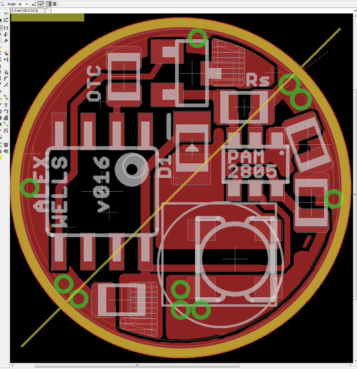
So I layed out an ATtiny13A and what I think is an entire PAM2803 boost circuit in a 15mm PCB w/ 0.75mm electrical and physical keepouts around the edges… The inductor I used is way too small I think. You can see in the image that I measured a 5.5x5.0mm rectangle, this is closer to a realistic inductor I think. Those are the approximate footprint dimensions of the inductor from a Lux-Pro 2D boost driver, although that inductor has rounded corners. With luck a modified clip will fit. (modified to clear the inductor)

Components around the edge, going clockwise from the ATtiny:
ATtiny
Capacitor (Offtime)
Sense resistor
FET for PWM (which may be miswired, sue me)
Capacitor (Output)
Capacitor (Input)
Inductor
Capacitor (ATtiny Vcc decoupling cap) (maybe we can delete it)

In the center:
Schottky using 0805 footprint
PAM2803

Clearly this thing has a lot of tuning up to be done. It may not work at all. Ever. That said, after cleanup I think this design will closely follow the PCB Layout Guidelines from the datasheet for PAM2803.

As I’ve explained elsewhere after reading the datasheet, PAM2803 appears to have Overvoltage Protection which prevents it from boosting beyond around 5.12v. This is how we are able to bootstrap the ATtiny off of it, even while using PWM to interrupt power to the LED. With many boost circuits voltage would spike, but the datasheet clearly shows a graph scope image! for OVP which I think is clean enough for the ATtiny to be OK.

Here is the PAM2803 datasheet.

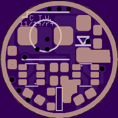
Here is v008 of the layout:

Reserved.

Can you give a possible suggestion what kind of light/host this can fit?

It’s a 15mm boost driver, potentially intended for 1xAA, 2xAA, and 1xCR123A applications. I have only a limited idea what hosts it fits in though. I was hoping other people would chime in on that, I have very few of those types of light.

Maybe Ultrafire C3 and SK68. Also take a look at comments in my recent 15mm DD+7135 driver thread maybe? [WIP] *15mm* DD+single-7135 driver - single sided Dual-PWM compatible using 3.3x3.3mm FET

I have made some prototypes with 7mm inductor, linear moonlight, voltage monitoring and ramp programmable modes (I don’t have the linear ML and VM programmed in my firmware yet). The problem is that I don’t have enough time to play with it. I need to make one more version with more space for diode so maybe I’ll end with just 5mm inductor. My previous versions used small diode and it didn’t perform very well. I also made a nice board for ATTiny10 but I realized that it doesn’t have an eeprom too late :-/ I have some useless boards now.

ATTiny10 version (quite useless)

Demo video

Nice! 15mm drivers open up the possibility of modding most AA-sized lights.

And if it is all going to work: will this driver have:

a) a decent efficiency compared to other boost drivers

b) a decent output current on a 1.2V NiMh battery, like over 1A through a XP-G2 emitter ?

In other words, apart from being able to have a custom UI (which is a wonderful perspective in a boost driver!), does it also outperform the middle-of-the-road boost drivers that come with cheapie lights?

Ah... I was under the impression its only for lithium cells!

so it can run of AA cells as well? thats great

  • 7mm inductor is quite large, is there a benefit for this application?
  • What component size and footprint size are you using?
  • I think your layout is never compatible with SOIC programming clips, right?
  • I will study your layout, besides teh programming clip compatibility it looks nice to me.

Don’t get too excited djozz! The PAM2803 is only the normal boost controller we find on common boards such as DQG AA/AAA lights, Fenix E05 (& probably others), DX SKU#128084, Nanjg-110, and many others.

The answers to your questions are “maybe” and “no”. No, it will not put out 1A from a single NiMH. The datasheet has a good and easy to understand graph on that subject, please take a look. Efficiency? I expect that to be similar to other similar drivers such as the ones mentioned above. Take a look here for HKJ’s review of the 400mA Nanjg-110. It is not very efficient: no surprise!

No comment on running it with lithium cells. It is a boost controller with a cap of around 5v for output and a minimum of around 0.9v (startup) voltage for the input. It’s intended for applications where input voltage is lower than LED Vf. Generally speaking that means that it is intended for driving white LEDs on 1xAA, 2xAA, or possibly 1xCR123A.

But the first of its kind where you can flash your own firmware! On an AA driver!?

Well, not the first to be created: driveX’s driver seems to be dated 10/14. :wink:

But yes, mine may end up being the first publicly available one where you can flash your own firmware.

Am I right in thinking that Pin5 (VOUT) is simply a voltage feedback pin?

The pin descriptions in the datasheet are not very useful. We’ve already got other pins for Switch and FB/SENSE, so I can’t imagine VOUT being anything but voltage monitoring…

Sure it should be a feedback for oscillator. It’s 5am now and I’m having finals at nine so I will get back to you later. Tomorrow probably, after getting some sleep :slight_smile:

Thanks driveX. I have updated my layout. For now I have assumed that VIN can have a small trace. Please let me know if you think that this is incorrect.

Good luck w/ your finals!

v016

  • FET for PWM was miswired. I fixed it, I think…
  • Made a new 0805 footprint (based on the Eagle one) which I hope to be meaty enough for easy hand soldering and inspection. The pads are the same distance apart from each other, but they are both less long and less wide. The white tdocu markings showing the component outline are the same as the stock Eagle 0805 footprint.
  • If you are willing to aggressively shave your SOIC programming clip or give up onboard programming, a 5.0x4.5mm rectangular inductor will fit (or a 5.5mm round one). With a 4.0x4.0mm inductor an unmodified SOIC clip should be a snug fit.
  • I used Eagle’s big, stock, 0805 sized footprint for the Schottky diode. This should have enough space for an adequate one, but if you need to use a bigger one you’ll just have sacrifice the SOIC clip.
  • There are 3x 0805 components on the board with no identifier. These are all 10uF capacitors.
  • LED- is at the top next to Rs / LED+ is at the bottom on the end of the capacitor.

What would happen if the driver was built with a high resistance sense resistor for a current a bit above the requirements of the drive and a barely glowing LED AND a FET in parrell with the sense resistor so to increase the output, the micro controller would have the FET turn on? I’m not sure that the PAM2805 will take kindly to this kind of treatment or if it would actually do anything for efficiency on lower modes.

I’m not really sure where you’re attempting to go with that line of thinking.

With weak cells or 1xAA you’d get the normal current for 1xAA. It’s not limited by sense resistance at low input voltages.

With 2xAA and strong cells I assume you’d burn the PAM2805 when you turned on the FET.

H-man, I have to completely agree with Alex here the circuit in the boards above is the correct use of this boost iC, can you link to a datasheet your looking at or why it is exactly you think adding those components would do anything different / better?

Can we back up (probably a topic for its own thread) but what is it your trying to do? Just have a higher current boost driver?

Don’t FETs of the size being used has an on resistance similar to that of the feedback resistor (~130 mOhm)?

The intent is to have the driver have a low mode without having it bounce off of the voltage limiter. My line of thinking is that with 2AA on lower modes, the PAM2805 would have to boost the voltage from ~2.4V to something below 3V with the FET off and then only have to boost to the relatively high voltage necessary to run the desired current through the LED when it is being pulsed. The current design has the PAM2805 bounceing off of the voltage limiter when the FET is off, right? That can’t be terribly efficient.

RE: The PAM2805 burning up: I shorted out the sense resistor on a boost driver that looks to be built around a PAM2805 or similar, it did not burn. There may have been some resistance in the circuit, but bypassing the sense resistor bumped current being pulled off of 2 eneloops from 1A to nearly 2A.

Has anyone prototyped this circuit? The basic PAM2803 circuit can be harvested from this cheap driver. Actually, that driver can be connected to any BLF DD driver for prototyping.

Can it be filed to fit a 14mm cavity? I wanted to put one in a brass AA light from Cnq / Banggood.