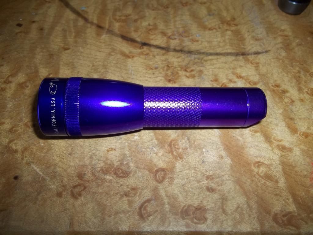
About a year ago I began building micro mags. I built them because I liked the form factor and enjoyed pushing the limits of what could be done with them. The incan mini mag is as high quality a host as one could want for the money and they were readily available from the local stores in a variety of colors. Another advantage was the huge amount of mods already done on these by the likes of Old Lumens, Match, and JohnnyMac. I've built around 20 micro mags in the last year and the modding techniques I prefer have evolved during that time. Lately I have been focusing on triple micros with mostly Nichia 219 emitters. I have outlined my process below for anyone that wants to tackle a similar build.
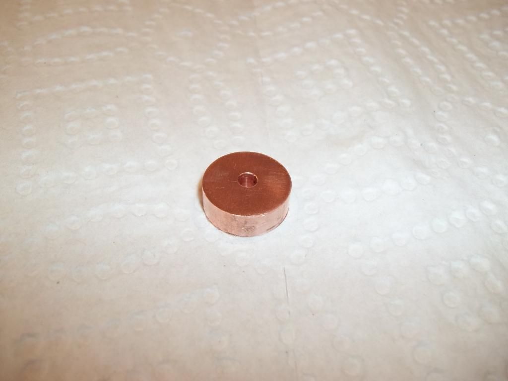
We begin with a chunk of 3/4 inch rod stock of your preferred heatsink material. I usually make mine out of aluminum but went with copper for this build. This can be sourced from any number of online metal dealers. Some file work to smooth and reduce to 0.25" thick plus a 3/16" drill bit equals one functional heatsink.
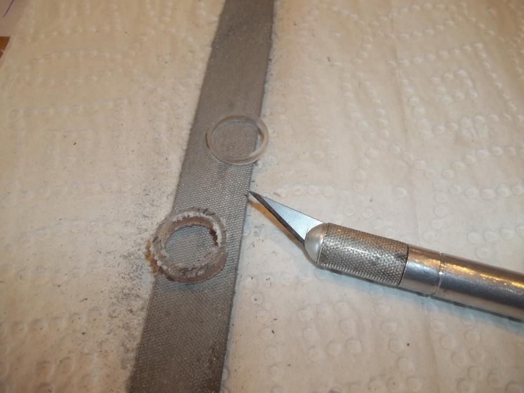
Now we need some method of securely holding the driver while simultaneously isolating ground from the host body. My solution is to build a plastic holder from some 18650 sized tubing found in some laptop battery packs. Two rings are cut out of the tubing with a hacksaw, one about 1/4" and one about 1/8". These should be smoothed and squared as much as possible. An exacto knife and flat file works well.
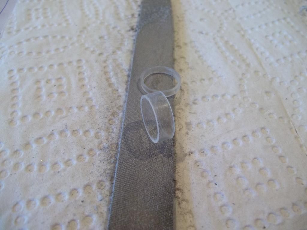
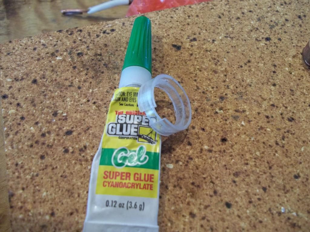
Split both rings with scissors and cut a small chunk out of the diameter of the smaller one, maybe 1/8". Fit the small ring inside the large one and adjust the diameter of the small ring to the diameter of the driver. We want snug fit. Glue them together with super glue and adjust the position of the inner ring so the driver will sit flush to the larger ring. Be quick as the glue sets fast! Scrape excess glue off with a toothpick before it sets.
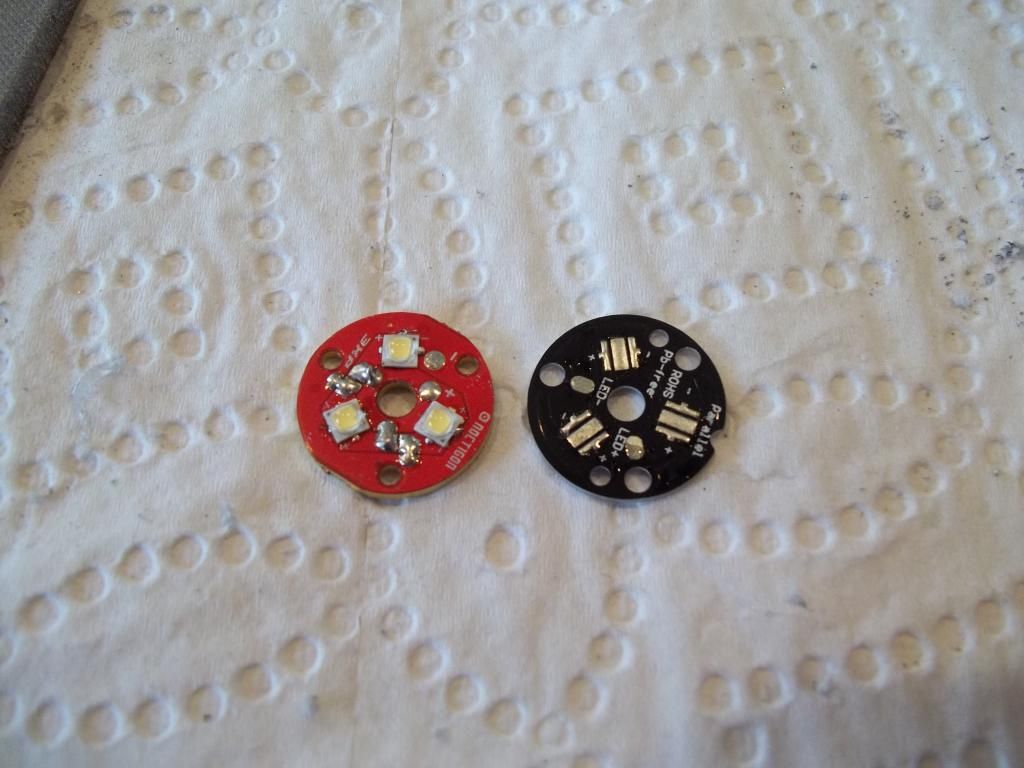
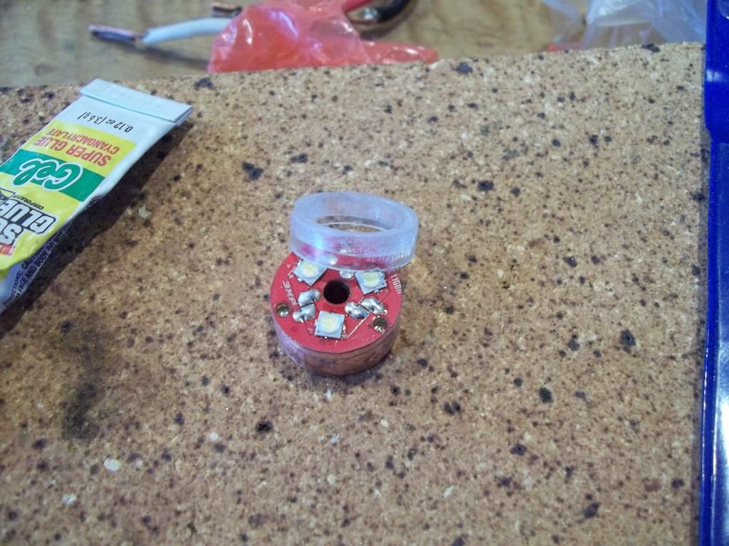
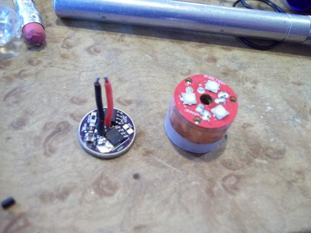
While we wait for the glue to set lets have a look at the triple board. Because I don't know how to do moderate, we need to use a noctigon triple board. I use the Kaidomain triple nichia 219 boards as a cheap source of emitters. Reflowing the emitters to the copper board is a simple process though sometimes frustrating and destructive.
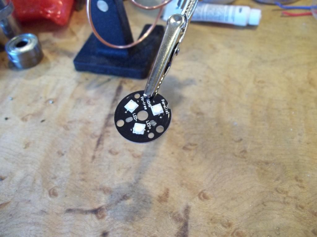
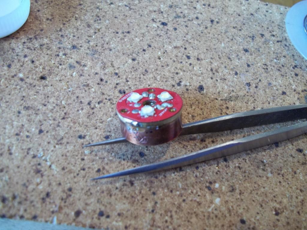
Since we're using a copper heatsink we can solder the triple noctigon to the heatsink for optimum heat transfer.
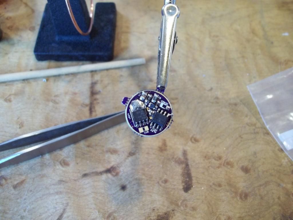
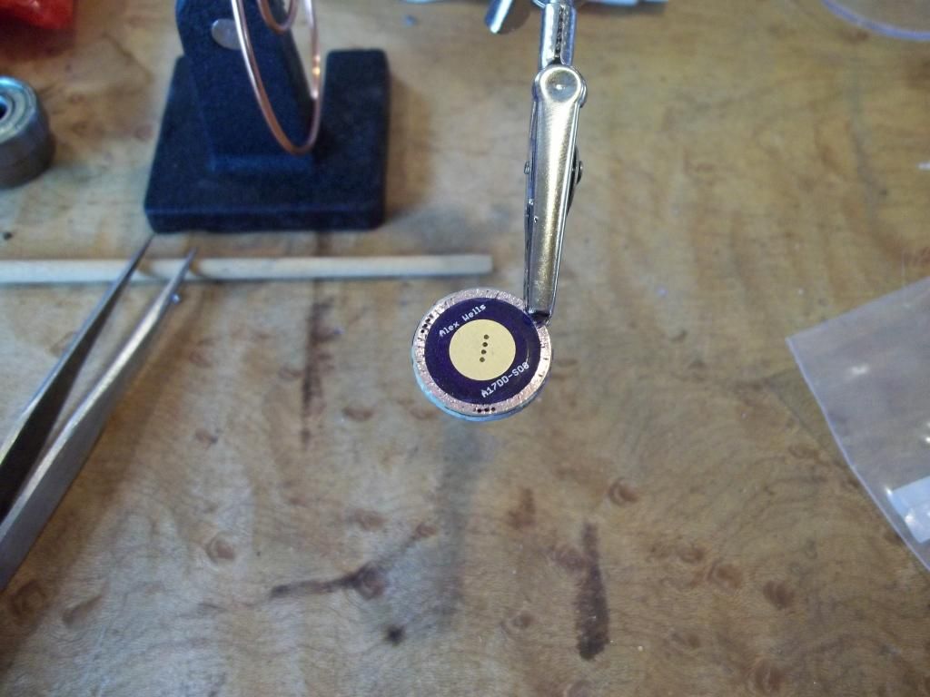
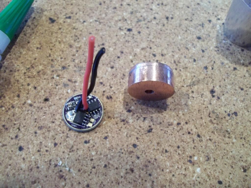
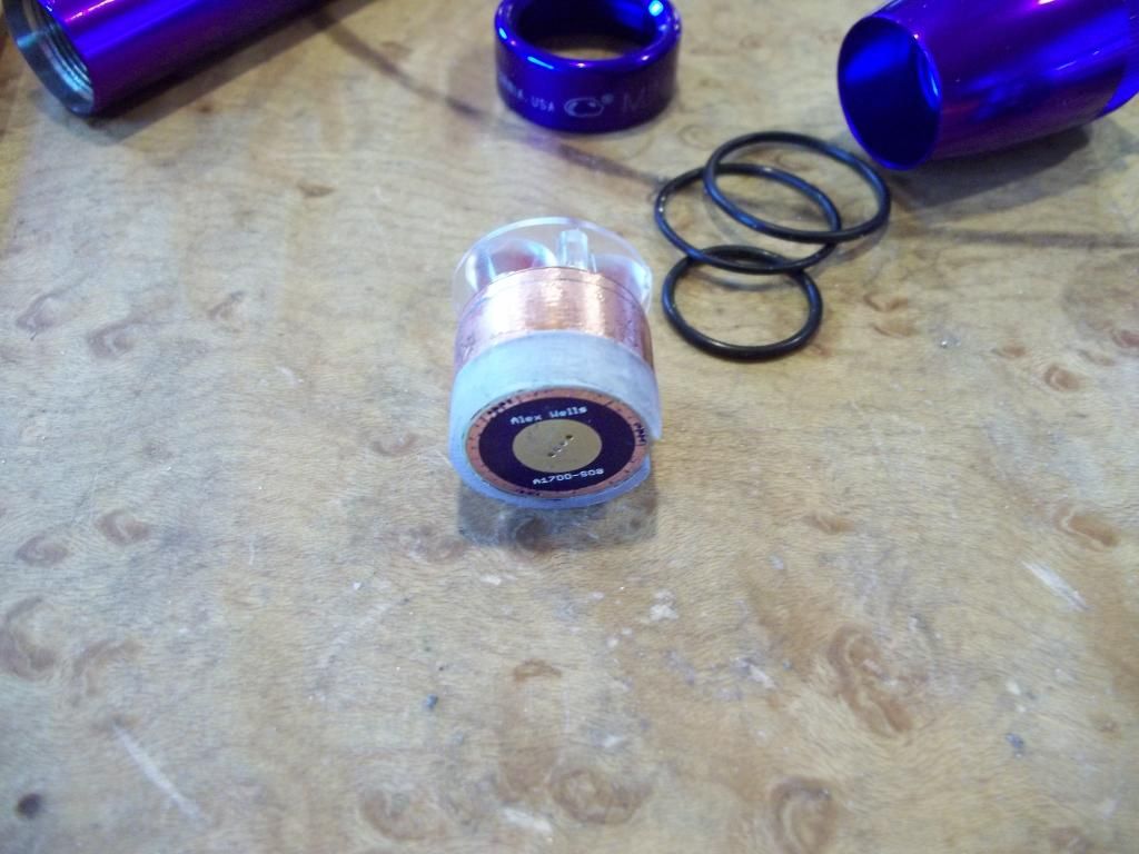
If one is feeling ambitious there are several hot rod drivers designed by various BLF members. I chose Wight's single sided direct drive FET driver because the component free battery side eliminates all sorts of complications. The negative mask on the rear of the driver needs to be scraped back to allow ground contact with the battery tube.
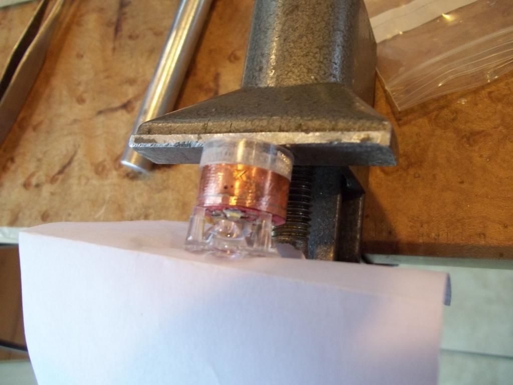
Now that the glue has set on our driver holder we can file the rear of the holder flat to sit flush against the back of the heatsink. While we've got the file out, lets file down the diameter of the noctigon to equal that of the heatsink.
Now lets glue the driver holder to the back of the heatsink. We may have to file the diameter of the driver holder slightly to get it to the same size as the heatsink.
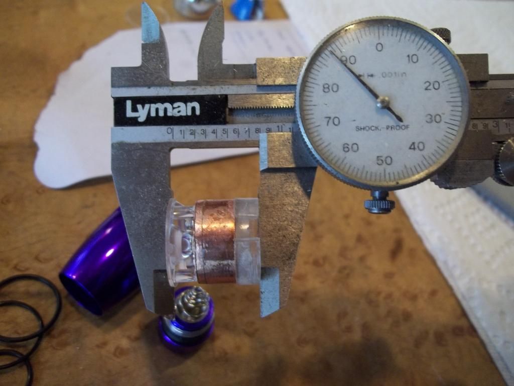
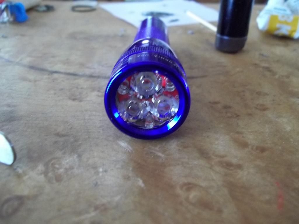
Time to finish the light engine. Just thread the wires up the hole from the bottom, snap the driver into our nifty plastic holder, and solder the leads to the noctigon. I use Carclo 20mm optics for these builds A quick check of the stack height confirms we are well inside the maximum amount of space available in the incan minimag head. If you're over about 0.85 you may need to rethink your strategy.
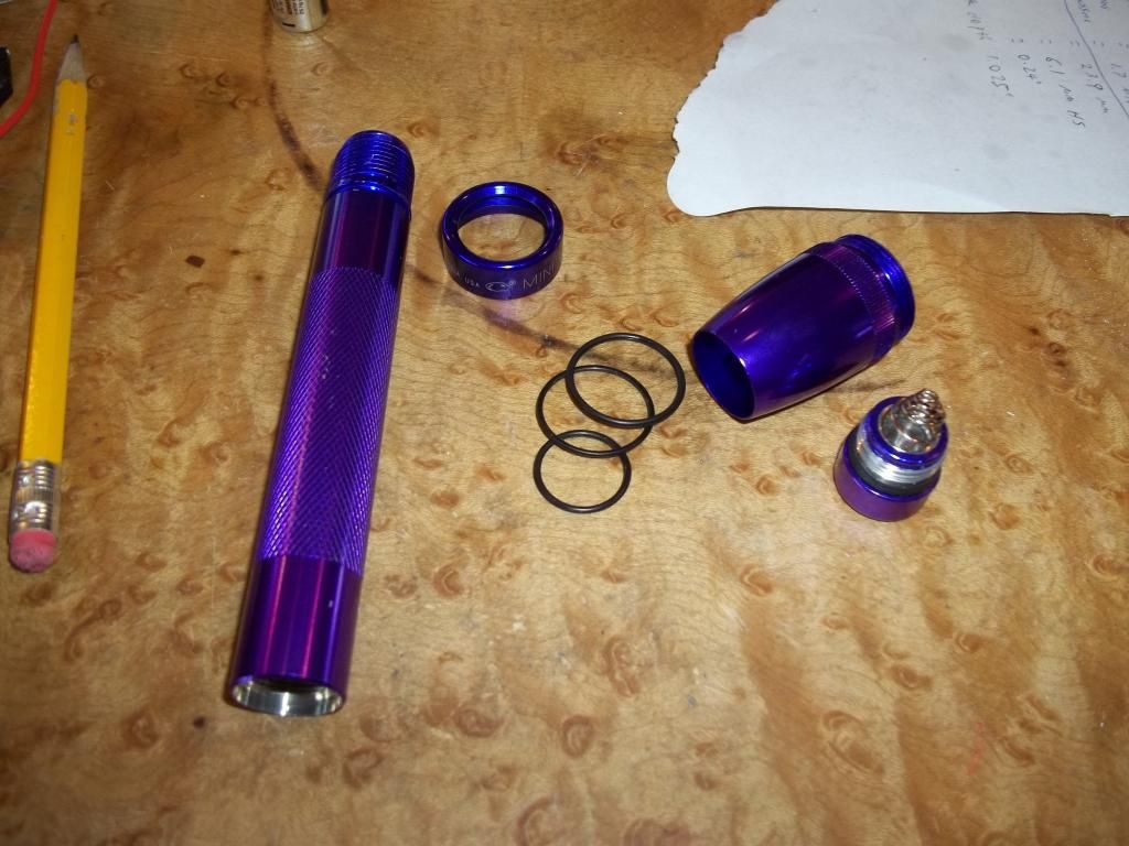
Now that we have a correctly sized and tested light engine it's time to re-shape the host. I didn't take any photos of the head boring process as that part has been well covered in Match's original 15 minute mini mag mod thread. I will reiterate that boring depth is crucial and that correct depth can only be achieved through test fitting. To that end, keep a container of cool water nearby for dunking the head into for cooling after boring cycles and a rag for drying.
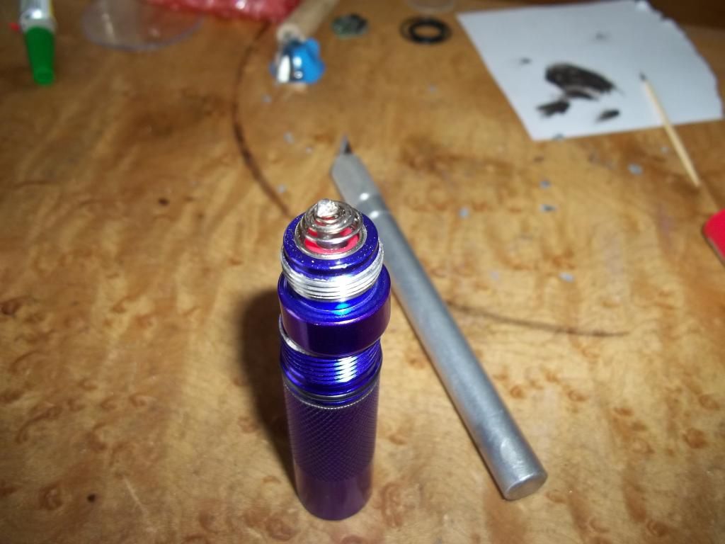
Begin by completely tearing down the host. Then cut it in half! We're looking for a total finished height for the rear piece of 1.95 inches. Mark and cut a bit long and then shorten to length and square up on a flat file. A hacksaw or chop saw works for cutting.
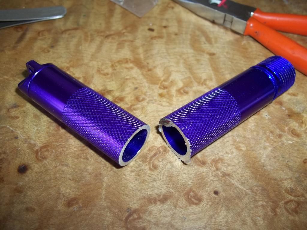
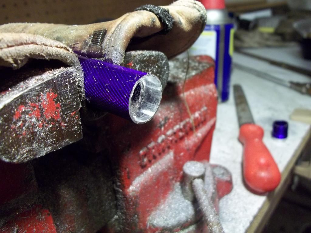
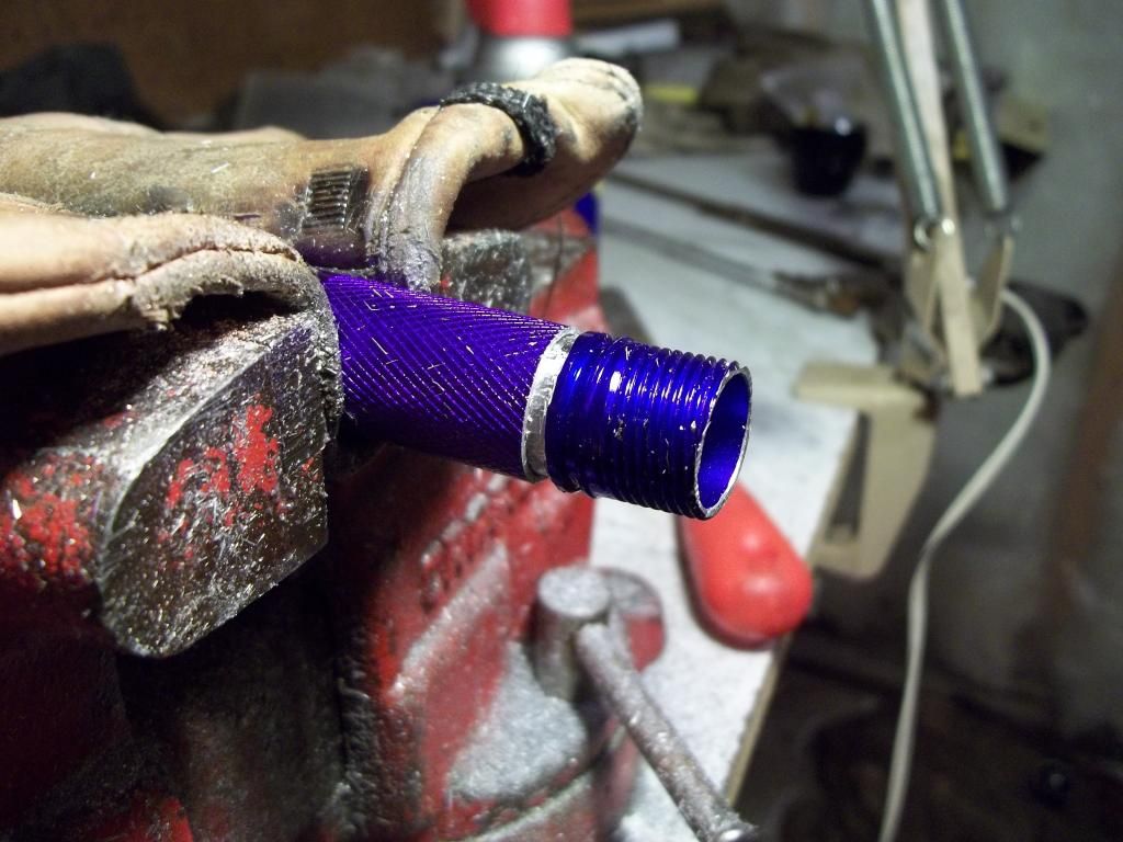
Now we take the two halves of the tube into the basement for some dremel work. Begin by clamping the front half into a leather covered vice and slicing off the threaded end with a hacksaw. We need to retain about 1/4" of the tube below the o-ring groove. As you can see I've already cut off the tip of the battery tube on this example. Turn the threaded portion around and clamp it back in the vice. Dress and square the cut with a flat file.
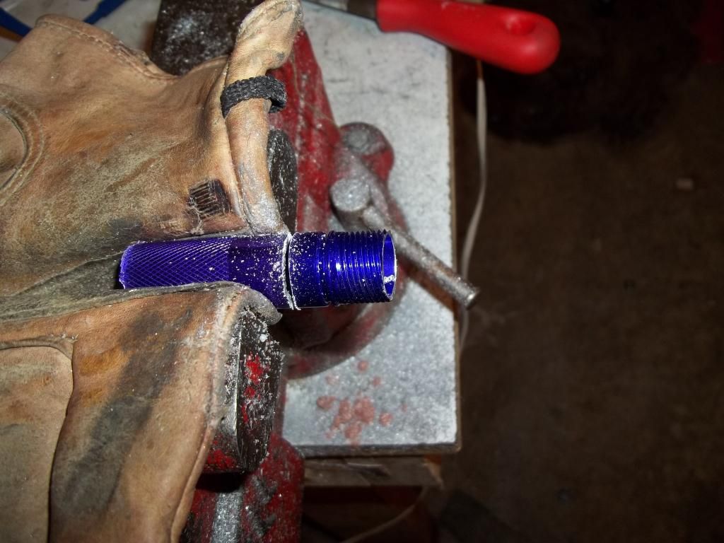
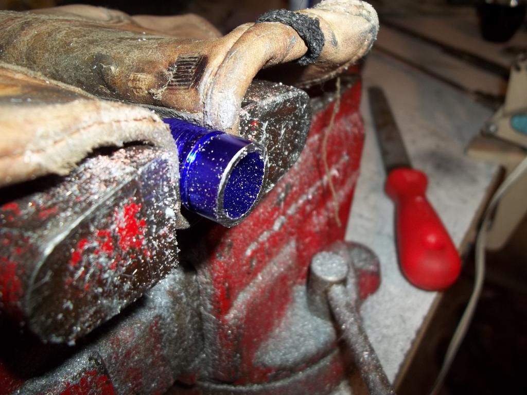
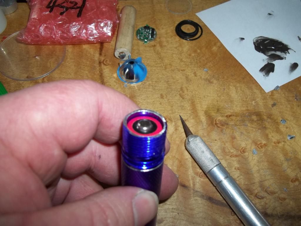
Now take a dremel tool with a metal cutting bit and cut a step just below the o-ring groove. Leave a millimeter or two of the flat part of the tube below the groove. We want to take a little more than half of the metal thickness in this cut. This cut need not be perfectly smooth at this point, we'll fix this later.
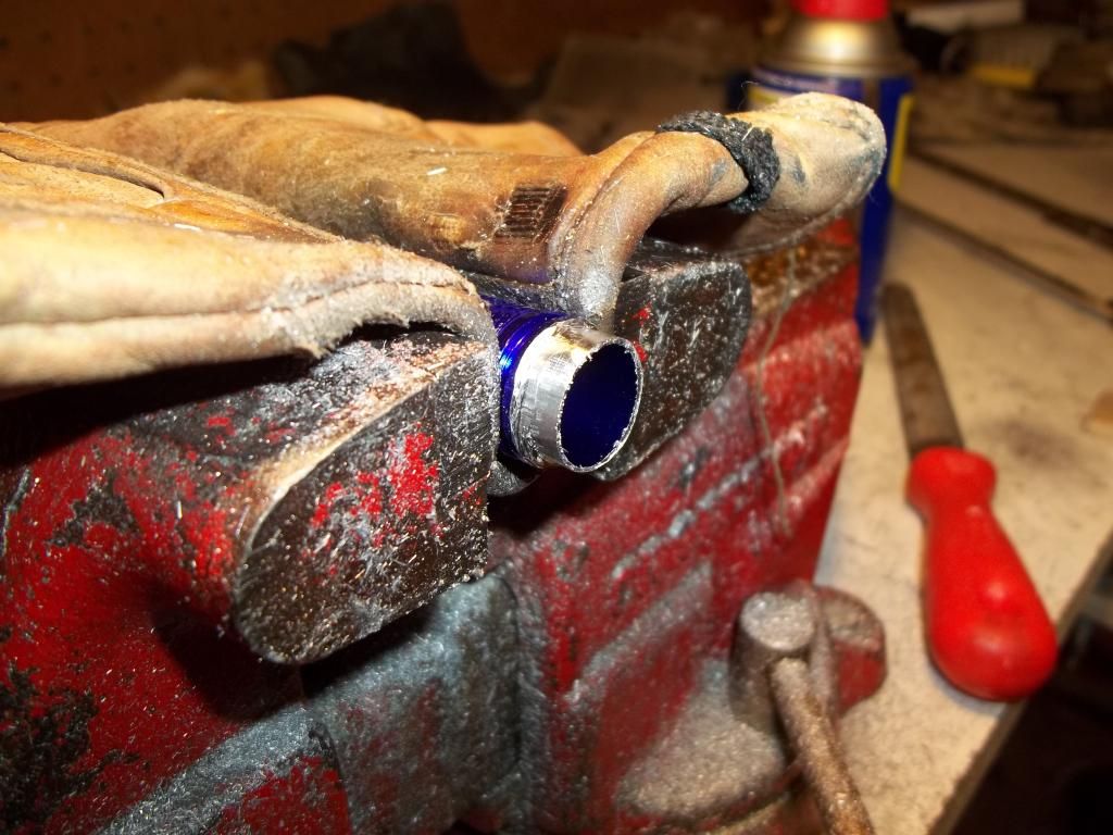
Next we clamp the rear part of the tube in the vice and enlarge the inner diameter until the front piece just barely fits in.
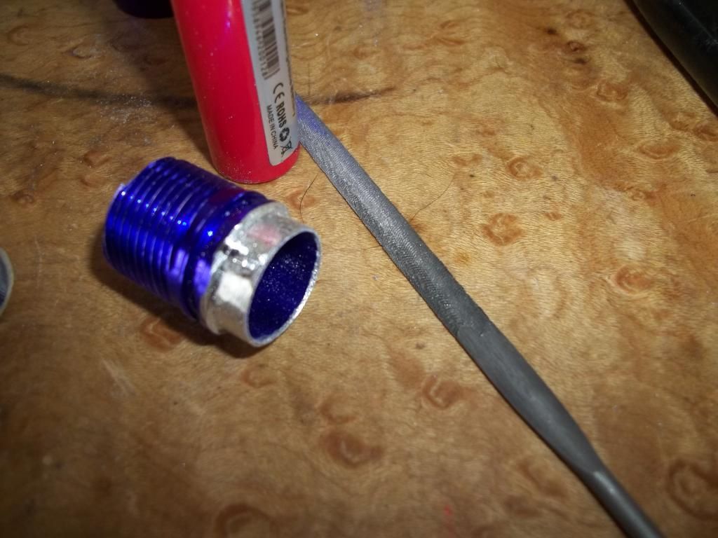
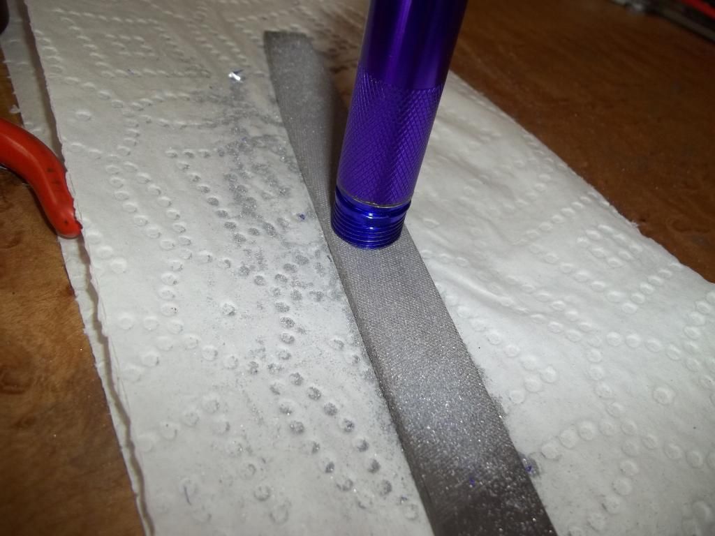
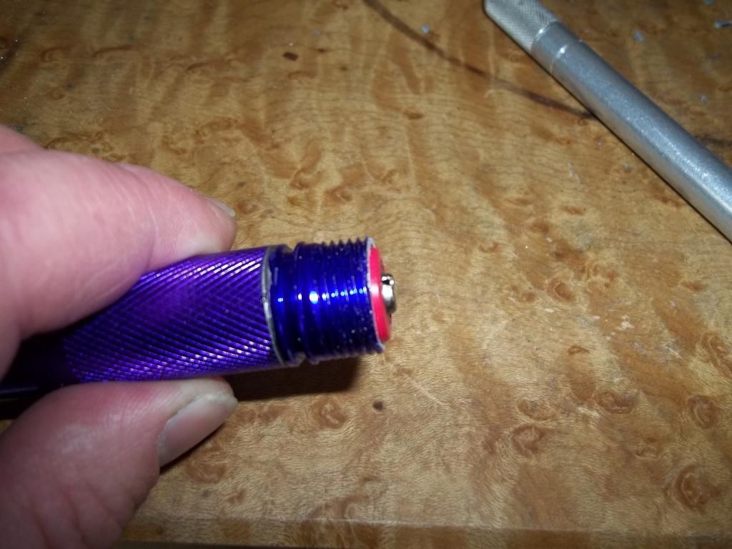
Well it's cold in the basement so lets go upstairs and clean up our parts. We want to square up the outside step we made in the front piece and align the parts so they screw into the head without snagging. This can be the most frustrating part of the entire process but sometimes it goes exceedingly well. When we get a workable alignment mark it with a sharpie. The mating surfaces that could come into contact with a battery should be eased with a round file to eliminate sharp edges and burrs. I use quick set JB Weld to join the two halves. Be careful not to get JB Weld in the knurling, it doesn't come out. Triple check that the tube still threads into the head easily while the epoxy is still wet. Sometimes the world is out to get you and these parts won't come back apart in any useful form.
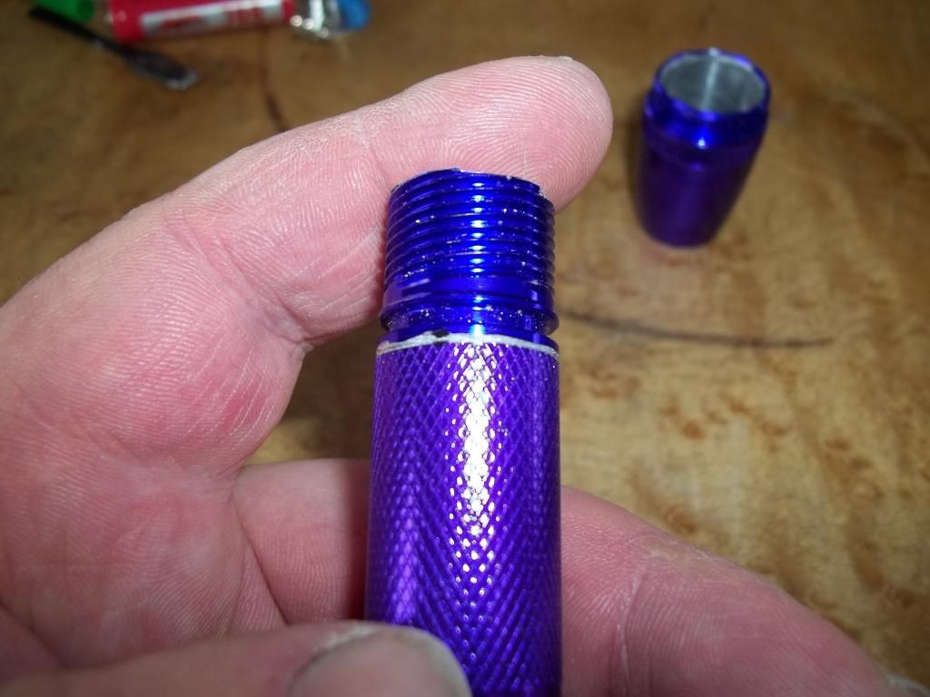
We're going to be drawing about 5 amps with this build so a tail spring resistance mod is is order. Just solder a Teflon wire between the extreme ends of the spring and coil it inside the spring. Now that the epoxy has set we can clean the excess from the inside of the joint and test the battery height.
Some elbow grease and a flat file gives us the perfect battery height.
And we're done!
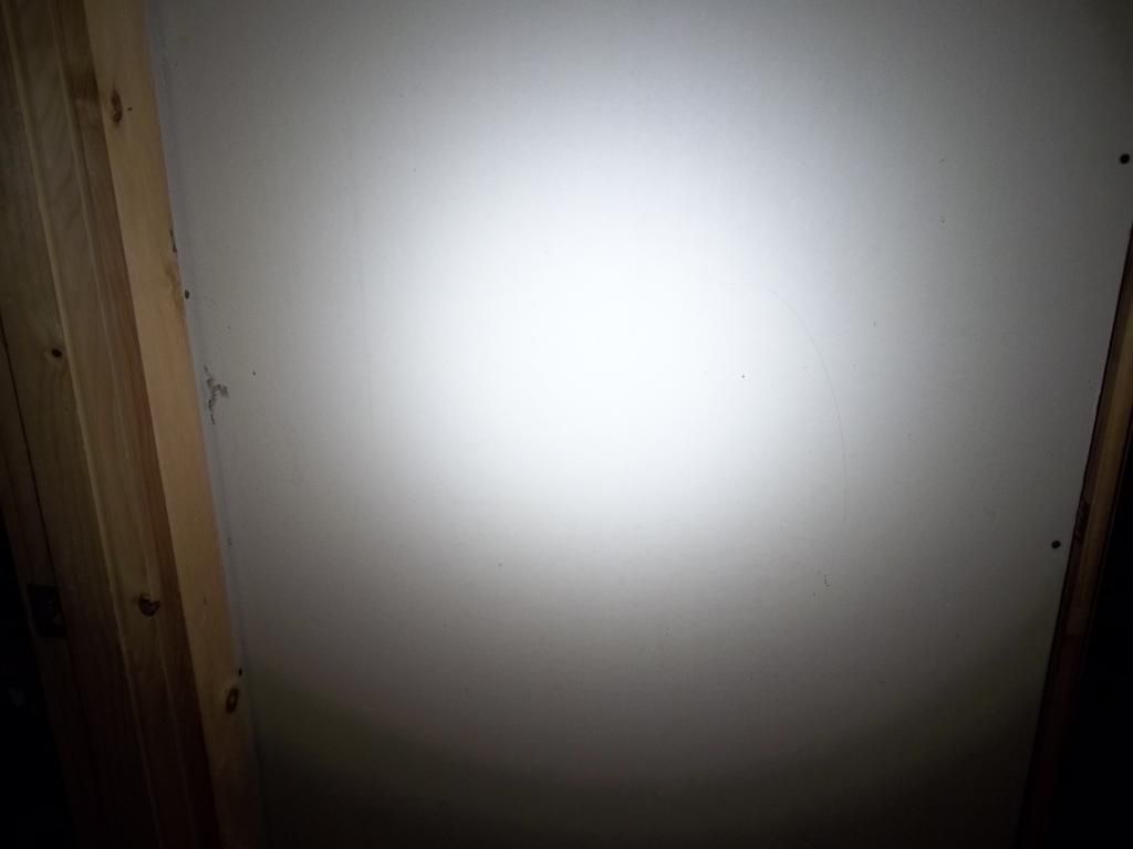
Nice tint and a smooth beam.
That's all there is to it. The vast majority of what is needed is patience, time,and attention to detail. Hope this can help someone.
Happy modding,
Brian
