So, this will be about the 6th K40/TN31 I have modified now with a 100% success rate soo far.
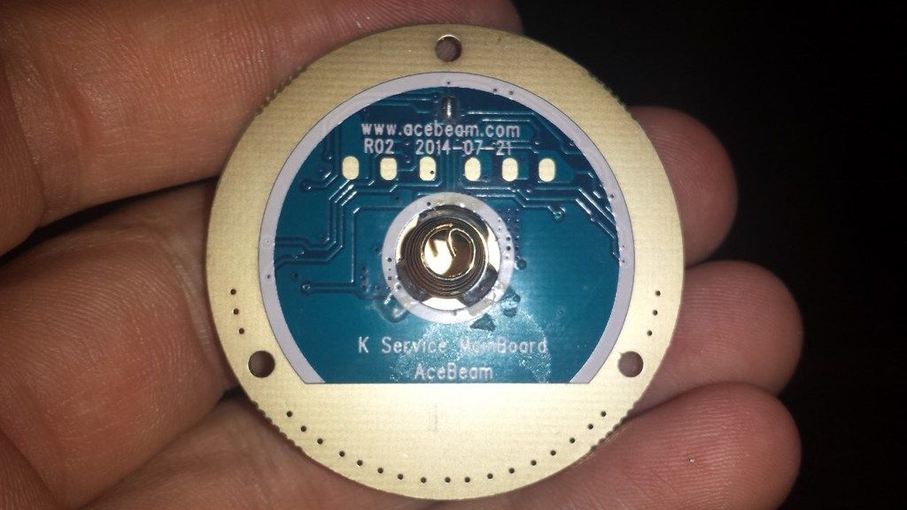
Anyway, a mate of mine wanted one so I ordered an XM-L2 K40 from HKE and after stripping it down, I have found they have changed the driver layout.
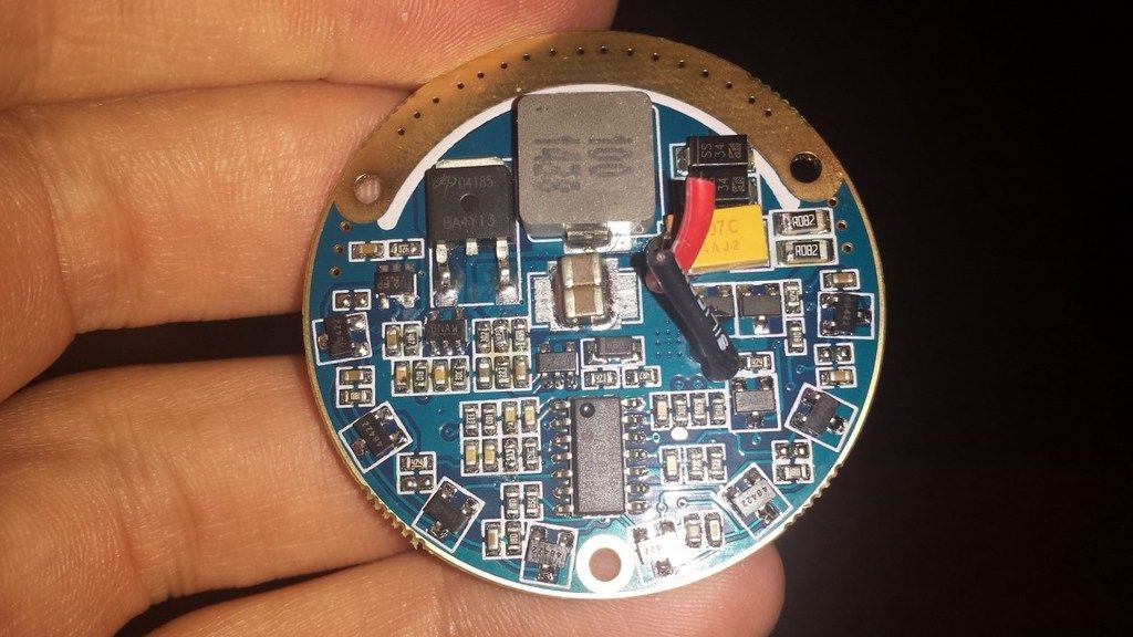
Now it looks to be as though they have just put all the components on one side of the board instead of on both sides.
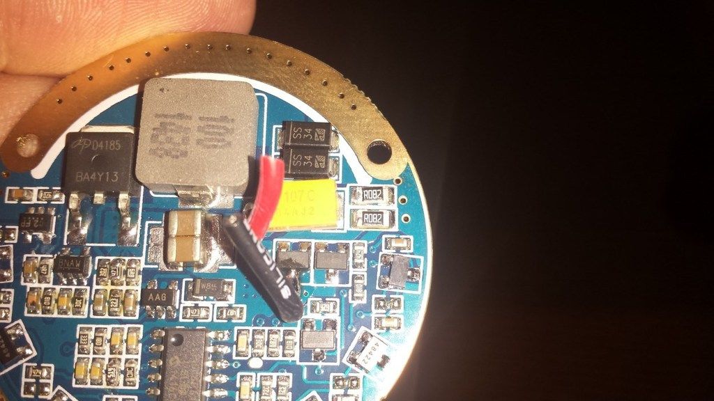
I just want to double check with those of you more knowledgeable than myself… that those two R082 sense resistors are the ones I should be bridging. Has anyone modded one of these drivers and can confirm for me?
They are directly before the capacitor which has the +ve LED lead coming from it.
Hmm, interesting. If the layout is the only thing that has been changed, you can safely bridge the two resistors to maximize output.
However, if Acebeam did additional modifications to the circuit design, there might not be a voltage limit that limited the output to about 4.0-4.1V, meaning it can feed too much current if bridging the sense resistors.
The layout seems quite similar though, and I don’t see a reason why they would remove the voltage cap, so I guess there’s only one way to find out.
Thanks for the response. I would love to hear from someone who has tried it already. If the light was my own one I would just go ahead and give it a go. It will be a bit annoying though if I cook it and have to buy a new driver when the light is going to a mate of mine anyway.
Well I tried it, turned the light on in lowest mode and all was working fine, started winding it up and the LED died at level 4. De-domed LED….
Now the problem is, I have had the exact same thing happen on a K40 I did ages ago (original driver) and I changed out the LED and it worked fine after that. I don’t know whether I should try another one in this light? I don’t want to keep killing LEDs…
Is there anything I could do to check this driver?
That’s not good news, to those who plan to mod the newer versions of the light.
The way to be sure is to solder on a precise resistor that would limit the current to what you’re comfortable around. I’d be fine with 5.0-5.5A at the highest brightness.
The sense resistors follow Ohm’s law, so adding resistors of the same resistance would double the current. The issue is that finding SMD sense resistors is pretty tricky. Maybe you can salvage some from existing lights?
I would recommend pulling the emitter and base to see if you see any thermal disconnects. I bought a TN31 once and there was a nipple in the center of the "pill" that only allowed a small point of contact at the point of the nipple and at the mounting screws. The thermal paste was around the nipple, but didn't make contact the emitter base.
If you have a problem like that, you may want to fix that and then try a new emitter with the resistance halved to .02ohms first. See what level of current you hit and go from there.
I have had that on a TN31 before, but prior to putting the de-domed emitter back in I polished both the emitter base and the torch shelf so they were like a mirror, there is no uneven spots on there anymore. When I removed the emitter to try another one there was a perfectly even application of thermal past underneath the whole board and I had only put a blob in the centre when installing the first time.
Confirmed that the driver is the culprit… Second emitter dead, both have been on TN31/K40 DTP copper boards so I’m certain heat isn’t the issue, turned light on in lowest mode, click click click then the emitter went really dim and that’s all it will do now. The MCPCB wasn’t even warm to touch.
So now my question is… Can I even put a lower resistance sense resistor in or will I have to go back to the standard R082s?
Alright, well I stacked 3x R100 sense resistors giving 0.0333Ω and it is now working again. With that set up I am getting 4.20A at the emitter. Although I am using some 8cm pieces of 18AWG wire with banana plugs to test it so there is probably some losses there. What emitter current do you think I will get if I stack another R100 for a total of 0.025Ω? Or I could even try one of the R082 ones I removed which would give 0.0237Ω? Unfortunately the only 1206 SMD resistors I have are R330, R100 and two of the R082s.
Does it make a difference with these lights if the batteries are at the full 4.20v or if they are at around 4.05V-4.10V? I assume the driver would regulate current until the voltage drops below a certain point?
I have had that on a TN31 before, but prior to putting the de-domed emitter back in I polished both the emitter base and the torch shelf so they were like a mirror, there is no uneven spots on there anymore. When I removed the emitter to try another one there was a perfectly even application of thermal past underneath the whole board and I had only put a blob in the centre when installing the first time.
Confirmed that the driver is the culprit… Second emitter dead, both have been on TN31/K40 DTP copper boards so I’m certain heat isn’t the issue, turned light on in lowest mode, click click click then the emitter went really dim and that’s all it will do now. The MCPCB wasn’t even warm to touch.
You're an accomplished modder. I should have realized when you said dedomed emitter in the OP that you would have already fully addressed emitter thermal path.
This is a good thread. Your experimentation and results documented here will help a lot of modders.
Thanks guys. Hopefully I can save someone else a few emitters in the future!!
Well I have currently stacked 3x R100s and 1x R330 which should be good for 4.62A at the emitter. I didn’t get a chance to bench test this afternoon as I had to head out. Will check it tomorrow.
Well I have bench tested the set up and I’m getting a steady 4.52A at the emitter, I assume the slight variance to the theoretical will be due to the 5% tolerance of the resistors and the lengths of 18AWG wire I was using to test it. Whilst it’s not as much as I would like, and if it was a light for me I would have definitely pushed into the 5.5A range. However, since this will be my friends first light I am sure he will still be more than happy with it.
I forgot to ask, did you happen to read the output voltage of the driver when the LED was blown or not connected? If it’s higher than 4.1V, that would confirm what the voltage limit has been removed.