Build: Dual XP-L headlight project.

Updated version in post #17

A couple of climbing buddies of mine that have seen and bought my hand held lights with my own drivers asked me if I do headlights also, and explained what they miss in current headlights. At first I said no, but after my old climbing headlight gave up I started thinking about it. The main idea is to have a light with a full flooder and a spotlight (not pencil beam, but useable for climbing), with an easy method of switching between the LEDs and mode levels. I decided to take the challenge and have been working with this project for quite sometime now. The ultimate goal is to build one entirely with my own design, both driver and host. I’m nowhere near starting with the host design yet, but I have finally reached the prototype stage for driver and firmware testing.

The first step was to choose a suitable host for prototype testing. I was initially looking at dual LED lights such as the SecurityIng, but for climbing purposes they are not practical as we want the buttons on top of the light, not on the rear. So I settled for this one: Review: Dual LED Headlight from Wallbuys. It’s a nice little light and could have recommended it, but in stock condition it suffers from some quality issues. I read reviews that the generic flood LED has died on a few, and it did on mine after using it during a mine exploration.

When taking the light apart I was glad to see that the driver would be easy to replace, so I designed one in OSH Park with the same shape and holes. Here is my driver (bottom) with the original driver (top):

I didn’t put any components or signal traces on that top left part as my end design will be smaller so I wanted to be able to cut if off easily. I kept it on the design as it has a screw hole and perhaps could be use for E-switch support.

Details of the driver:

  • 4 layer board with dedicated power, signal and ground planes.
  • MCU is ATtiny84V, 14 pin with 12 in/outputs, 8K of programming space.
  • 7 x 380mA 7135 chips per LED. Each group of 7 controlled by 3 outputs from the MCU, enabling any amount of chips from 1 to 7 to run as constant current modes.
  • The single 7135 outputs are on the MCU’s PWM capable pins, allowing lower than 380mA modes.
  • Back side of driver board is ready for 8 additional 7135s per LED if increased output is desired in the future, each group on their own output pin from MCU.
  • Off time cap.
  • Zener ready for future MT-G2 or XHP option.

I had the driver board for quite some time before starting, and then programming the firmware to an acceptable prototype level has taken it’s time. My test setup:

As the firmware is now in a usable state I could finally stick the driver into the host. I replaced the original switch with an Omten switch, drilled another hole and put in an E-switch I had lying around. I cut off that top corner as it turned out to be in the way. Component side is towards the back, leaving a relatively flat area for mounting the LEDs. It’s not a pretty build so far, but good enough for prototype testing.

I soldered together two stacks of copper washers and soldered on the XP-L LEDs. I chopped of the end of the reflectors so the LEDs would fit all the way in while soldered to the washers, isolated the unpopulated side with kepton tape and removed some unneeded internal plastic.

It was a bit of a hassle putting together all the pieces, needing to stop to cut and file the plastic several times to get it all fitting. It finally went together:

I need easy access to the MCU as the firmware is no where near completion, so I cut out a hole in the rear. Putting the MCU on the inner side might have been practical for using the MCU’s internal temperature sensor as this temporary host is plastic, but no way I’m a going to screw it apart between flashing. For the final host design I might move it to the other side, but on the other hand that will be an aluminum host designed as a solid heat-sink and I should be able to get readings from the back. I could also use an external sensor.

I still have plenty of work on the firmware to do, but this is what I’ve done so far:

Interface one:
1 long press on mechanical switch toggles between LEDs. 2 long presses after each other enabled both LEDS.
Short press steps cycles through 3 modes, mode direction up only.
Boost mode (turbo) enabled with E-switch only. Holding for less than 1,5 seconds gives short burst (good for signaling to climbing buddy). Holding for longer sets boost mode on until timeout (or additional press) so E-switch button can be released (short blink notifies). Reverts back to mode that was active prior to engaging boost.
Each LED configuration (spot, flood or both) has selectable LEDs for the boost mode. For example: when only flood LED is on, boost is configurable to activate any or both LEDs, and then revert back to flood only when boost disengages. Currently hard coded LED selection, will be user programmable later.

Interface two:
Short or long press toggles between LEDs, double press activates both.
Short E-switch goes to next mode, long E-switch press goes to previous mode. Boost mode is in the mode array, selectable just like the other modes.
Boost times out back to the mode that was active before engaging (lowest or highest mode).

Other stuff:
When both LEDs are on they use separate mode level values (not the same as when a single LED is on alone). This makes it possible to obtain desirable balance between spot and flood in dual LED mode. The mode values are currently hard coded, will be user programmable later.
Boost time out half the time if both LEDs active.
Individual mode memory for each LED configuration (spot, flood, or both).
Voltage monitoring with step down. Boost mode is prevented when voltage level is low or critical.

Hidden functions activated while holding E-switch on startup and counting blinks:
Moon mode, voltage readout, safety lock, interface selection, critical voltage turn off or stay on, reset to default/factory settings.

I added the selection of what the light does when critical voltage is met because it’s a light designed for climbing and caving. In a critical situation you might not care less about a cell and would not want the light to turn off when you need it the most.

This is all pretty advanced, not for all users, so the idea is that it should work pretty well out of the box, and only those who are interested in configuring it should need to read in-depth instructions. Besides my own testing my girlfriend and one of the climbers who gave me the idea will receive prototypes for evaluation and feedback about all this, so this all might change later.

Still to implement.
All modes user programmable.
User selectable mode memory. Remember mode separately for all LED configurations, remember only current mode when toggling LED configuration, or no mode memory at all.
A few more interface options to choose from.
Possibility to run of 3 x AA cells with selectable firmware adapted for AA use (replaceable battery case required).

Still a lot to go, and the light is pretty ugly, but it is usable as long as it’s not raining:

By the way, anyone know where I can get coiled/springy 22awg wire? The stock coiled wire is unusable so now I just have normal wire which is hanging out of the side. Pretty annoying.
Also looking for a better 18650 battery case, both single and double cell cases are of interest.
Reserving… Probably won’t need it, but why not.

Very nice concept and build. Really like the independently adjustable LED's. Effectively makes in many lights in one package. Is the floody beam pattern similar to a mule or is there some shaping of the beam?

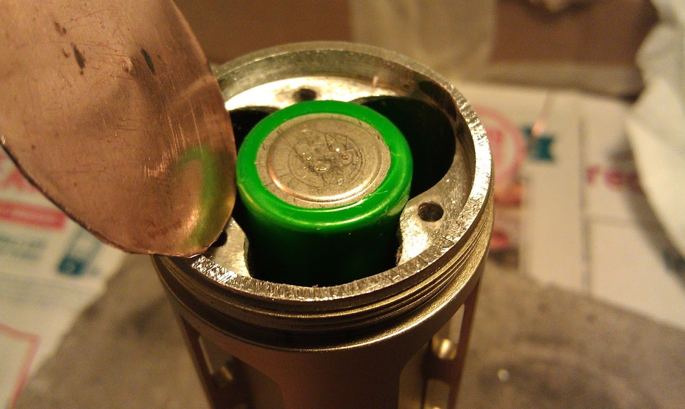
Copper spring? I imagine you know this, but just in case. It is fairly easy to make springs from copper, but they do take some maintenance. Simply bending the copper wire into a spring shape will give is some springiness. You then stretch and compress the coil until it gets the desired springiness. Some times, when removing a battery, you will need to slightly stretch the coil.

If the coil starts to become too stiff, it can be annealed (heated until black or dull read and dropped in water to cool fast). You then need to stretch and compress to get to the desired stiffness again.

Instead of springs coils, I like to use sheet to make thick copper "springs". Domes are naturally strong:

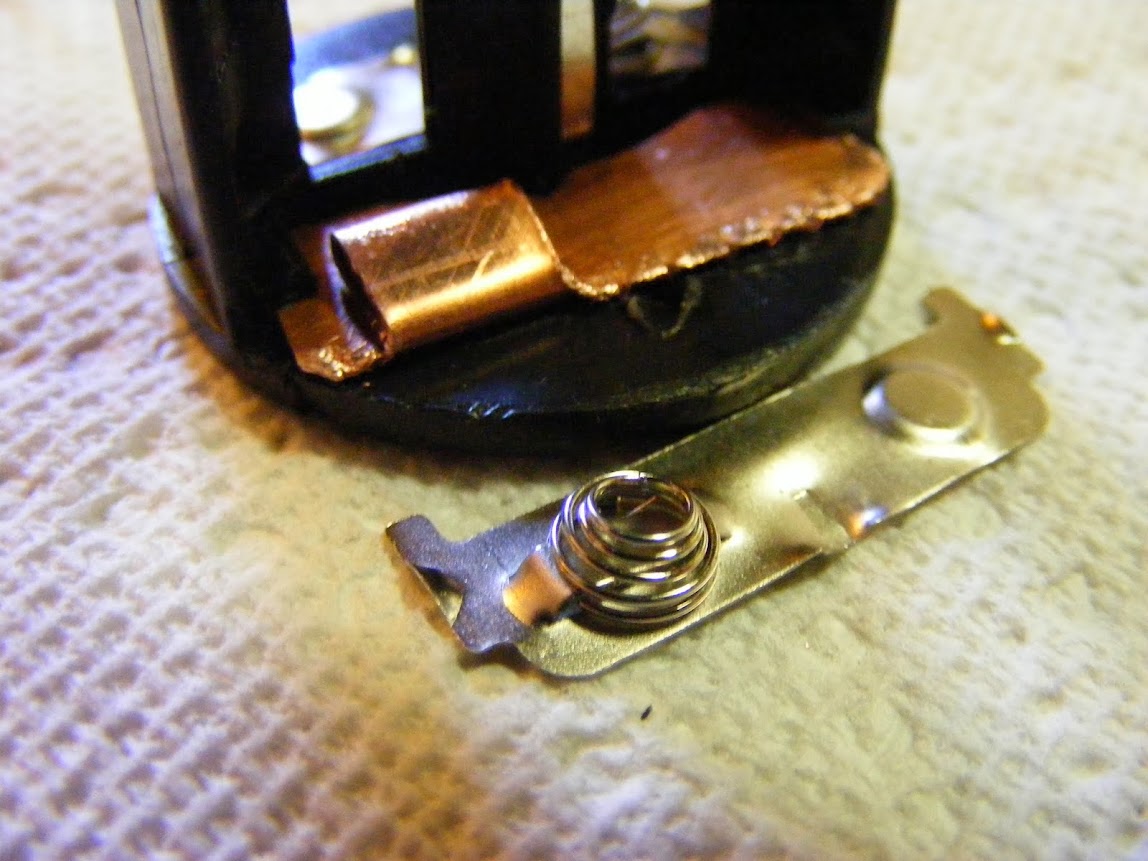
Or big loops like below. The end of the loop curls under and back up against the underside of the hump.

I find the dome only needs one or two "stretches" (basically just tapping the dome back in to original dome shape) and they are good for a very long time. I actually have not had to adjust a loop like the below pic, but the same process described above would apply if they did.

Hope that helps. Really digging your concept and execution of this headlamp.

What an amazing build Mike C. Your skills are without doubt and your buddies are going to end up with an orsm light. I always had a motto, a friend in need is a pain in the ass.

Thanks! The idea is to make this light configurable to suite many needs, and I have the programming space to do it. Suggestions are welcome.

It has a dome shaped plastic lens over it and the beam is almost entirely circular. The protruding plastic casing around the spot LED gets a little in the way off it on the side so I’m going to file it down a little.

It’s not springs I’m looking for, it’s the wiring that goes between the battery case and the light. My description sucked though, it’s not “springy” at all. The original wire is a coiled wire that stretches when fitting the light over a helmet, but I can’t use it as the internal wires are far too thin for my liking. I’m looking for a similar coiled stretchable wire but with two 22awg strands in them. The red and black wires on my build are just hanging off the side when the light is not on a helmet, and it’s a little annoying even for prototype field testing. The original coiled wire looks like this, and is what I’m looking for but with thicker internal wires:

Thanks :slight_smile: My buddies planted the seed but it didn’t grow into an actual project until my old climbing headlight died. By that time I’d gotten rather used to designing drivers, and as the “perfect” headlight for climbers doesn’t exist, way not make it?

Nice work, Mike :slight_smile:

GarryBunk has sourced a nice power cable that uses the same type of connector that has what he believes is 20ga wiring. It does not have the spirally spring section though. I'm thinking that can be achieved by wrapping around a small dowel, heating the wire, and letting it cool in place. Just a hunch. You should Google this idea and see if it will work for you.

The wire Garry found has a male connector on one end and female on the other. The connectors should be compatible with typical bike light power packs.

Thanks!

Heating, didn’t think of that. Well worth a shot.

Do you know if the cable GarryBunk used something like this?: http://www.dx.com/p/5-4mm-male-to-female-extension-cable-for-sku-29489-30864-100cm-32751

Heating should work.

When I re-magnetize screwdrivers by wrapping wire around them & shorting the wire across a car battery, it tends to keep the spiral shape. Just don’t leave it hooked up too long if you try that method….

Great stuff but I suppose waterproofing is important while climbing mountains?

Of coarse. The end idea is to design my own host and have it machined, with the goal of it being waterproof (not for diving though). So far this project is only in the prototype stage to test the driver and firmware functionality.

Designing driver boards is cheap so mistakes don’t cost that much. Getting a host machined is a different ball game. I certainly don’t want to go through as much trial and error as I have had to with driver boards. I need to prototype test everything before getting hosts machined, like lenses, reflectors, which buttons I’ll use, helmet mounting etc etc. This is just first stage functionality testing of driver and firmware, nothing more… yet.

Mike C wrote:

Do you know if the cable GarryBunk used something like this?: http://www.dx.com/p/5-4mm-male-to-female-extension-cable-for-sku-29489-3…

Yes, that is it. Sorry, didn't have time to find it this morning. He sent me half of it to install in the bike light I am building for him. We are using PG7 Cable Glands to have a water proof connection to the light. They are a good match, but you may find the cable glands too big for your application.

Thanks for the tip! I’ll look into size when I get there, having water proof connections is a must, at least when I start thinking about a real host.

Progress halted for a while. I’ve made changes to the driver design and need to wait until OSH Park send me the new boards. Pins and functionality is a little different, so no point in continuing coding the firmware until I have a new driver assembled.

Now I have time to start on another project that’s been lying around for ages…

What guage is something like shaver or clipper cord?

I’ll be using cord from a car cigarette lighter extension as I did in post #1192 in this thread: What did you mod today? - #1179 by Mike_C

It appears to be about 22awg, not sure though. According to the packet it’s rated for 10A.

I’ve updated this project a little… I’ve made a new more compact driver which I intend on using in the final headlamp casing which I intend to have machined from aluminum (once I get around to CAD design and all that stuff).

I’d bought three of these cheapo headlamps so I can play around a little. My first version was a hassle to take apart I just took another one for this next stage. As my new driver is smaller I could keep the inside plastics to hold all the crap together. I chopped up an alu heat-sink and used artic alumina adhesive to keep the washer spacers in place:

The power cable to the battery case has been bugging me a lot. Thankfully I found the solution:

I used it successfully on another headlamp (post #1192 in the “What did you mod today” thread: What did you mod today? - #1179 by Mike_C) so I took the other half of the cable and used it for this project.

The idea I had for this stage of the project is to start evaluating which optics to use. I threw out the original headlamp optics and installed a 10 degrees lens for the spot (http://intl-outdoor.com/2-pcs-cree-xml-led-optic-10-degrees-p-474.html) and a 60 degrees lens for the flood (http://intl-outdoor.com/2-pcs-cree-xml-led-optic-60-degrees-p-471.html). So far I’m fairly happy with these optics. The spot is good, works great for climbing/caving purposes, and the flood is fairly wide. For actual climbing in the dark it could be wider, a bare LED is the most usable in that case, but that’s not so versatile for other uses. Time will tell if I end up using them in the final project. I do like that both optics have the exact same dimensions, it would make designing a case easier.

I’ve also updated the firmware. I took my X85 firmware with dual switch, ported it to the ATtiny84 and added the LED selection function (to select spot, flood or both). When testing the firmware I got real fed up with the clip always falling of the ATtiny84. As I’m using a new case for this stage I didn’t cut a hole in the back this time, I soldered on the clip wires directly to the MCU and feed them out through the side of the headlamp. When I need to flash I connect each cable to the USPASP, and when I use the headlamp I just tape up the cables with the headband. I’ll keep those cables until I am happy with the firmware.

So I’ve made a little progress. The next step will be the case design… I’m not looking forward to that and might seek outside help. First I have to make sure these are the optics I want to use, I can use that as an excuse to postpone the case design stuff for awhile.

a very interesting project :slight_smile:

iv been planning somthing similar for a diving torch, but so far the programming an switching is beyond my knowlage

keep up the good work

Thanks. Welcome to BLF by the way.

I aim to make the case waterproof when I finally get around to designing it. It’s going to be a headache solving the two switches, optics and cable I guess.

thanks for the welcome

you should be able to find a small enough cable gland at somewhere like RS iv had some in the past that were only 10mm diameter and about 15 long i think. otherwise you could just pot the cable entry with silicone.
optics again would probably be easiest with a thins smear of silicone around the edge to glue them in.
as for the switches, for diving i use piezo switches but they would be overkill for this light and are quite bulky. ( unless you want to use bare piezo elements and write more code to be able to use them)

i used to design and build my own diving lights but have been out of the game for a few years. just starting to get back into things now.