FmC's Hand Made DIY 2015 comp entry; "WW2 Searchlight". Finished!

---------------------

Below is the real-deal, of which I intend to make a scale version. It won't be an identical copy - that's not my intention, but I aim to make it fully functional.

I guess it will be more of a "spot lantern". It will be portable, but it's not something you are going to walk the dog with. :)

--------------------------

Problem solving.

* Decision; I was planning on doing a Recoil type setup, & this is still my preferred option.

To get any type of real concave mirror in the size I want (~30 cm), is very costly, so I'm currently thinking of finding an appropriate size dish/bowl, & coating it with a layer of adhesive mirror sheet.

Conclusion; Find / make true parabolic reflector.

Done! Parabolic reflector made using the spin-casting method.

---------------

* Driver help;

Will one zener modded BLF DD driver v1.0 (older style FET) be able to handle 4 * XHP70's in parallel?

Conclusion; Specs say no...

....Or, can I piggyback 3 or 4 FET's on the same board, & will the 13a have enough drive to operate them all?

Conclusion;

Looks like I will be running two separate drivers.

--------------

September 20th - Finished!

:beer:

-----------------------------------

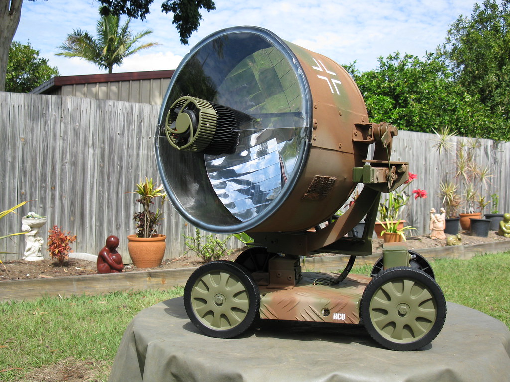
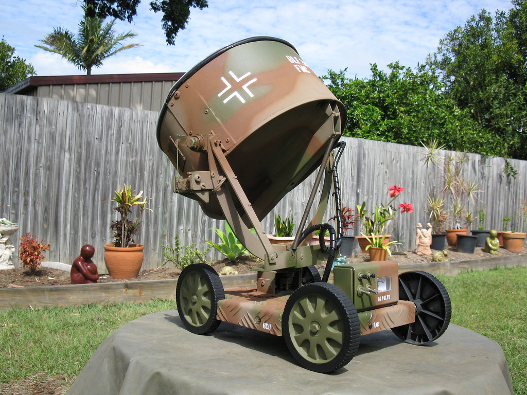
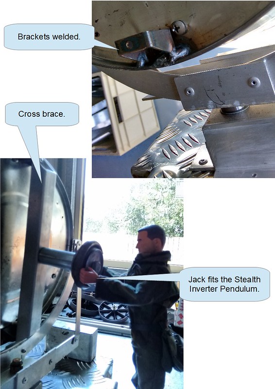
I'd like to introduce everyone to "Jack".

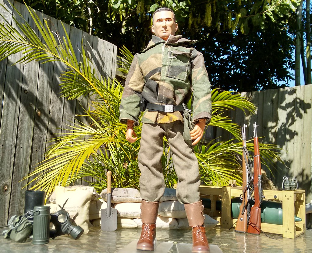
He's retired now, on some kind of pension apparently, but he tells me he was once in the Special Forces, & even spent a few years behind German lines as an Informant.

I dunno - he seem a little young though.... (personally, I think he's full of it...)

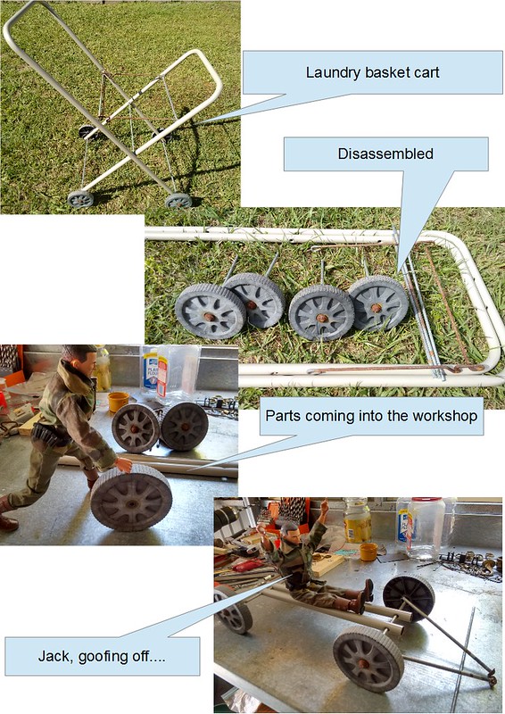
Anyhow, I bumped into him at the scrap yard, while I was on the hunt for parts for the build, & he seemed keen to help out as an advisor.

I expect to see Jack pop up at times during the build process, & of course, I'll need his expertise to operate the light once it's completed.

-------------------------

Reflector

(18th July)

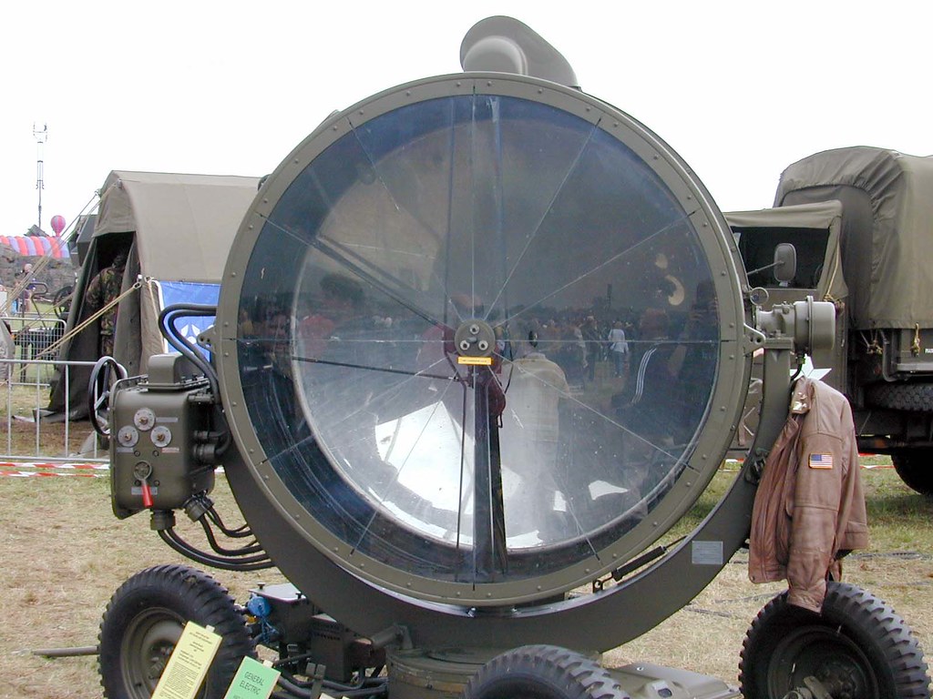
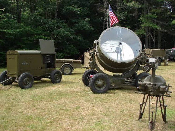
The big parabolic reflector is really the basis of this build, & it has to be done right in order to work properly.

To keep things in the DIY & Budget spirit, I had to have a go at making one.

After a little research, I was able to measure out a parabola with the dimensions & focal point that I needed. I then used the template to fabricate a wooden cut-out.

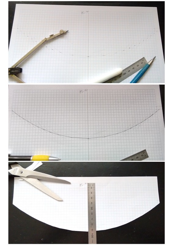
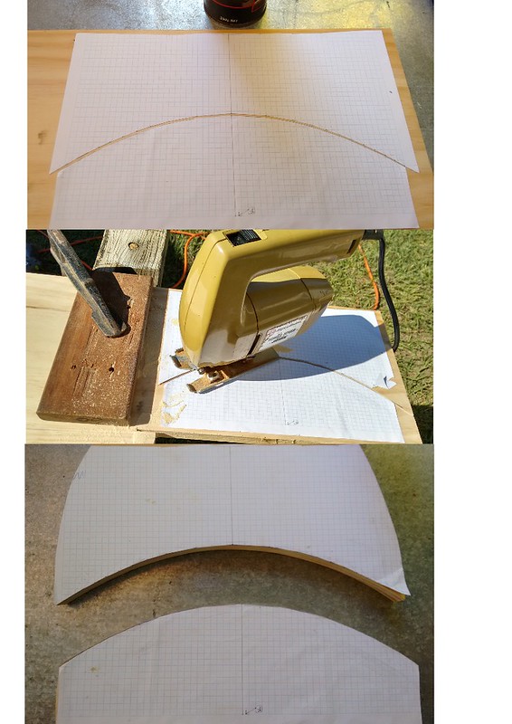
The Idea was to use modeling plaster in a bucket, & shape it into a parabolic dish, by rotating the wooden cut-out around like a paddle.

I tested it with the dry powder first, & it looked as if it would work well.

But when I mixed the powder in the bucket, I realized that I had nowhere near enough, & quickly rummaged through the shed & found some tiling grout, which i added to the mix.

I still didn't have quite enough mix, & by this time I realized that it was going to weigh a ton even if it did work.

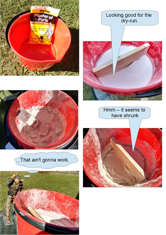
So I'm going to chalk this one up as a failure, & I will probably have to lash out & get that nice Edmund's Optical reflector instead....

___________________________

Reflector, part 2

(2nd August)

I was soooo close to buying the Edmund's reflector on the weekend. I made an account, added to the cart, & got through to the shipping page..... another $35 shipping, thankyouverymuch.

...I don't think so.

I emailed them for other shipping options, but that is the only option they offer.

...& why did I almost do the non-budget thing & buy that expensive reflector? Because of what happened on Sunday;

I had been keeping an eye out for another solution for the reflector, & I came across this fine wire mesh food cover for a couple of $$.

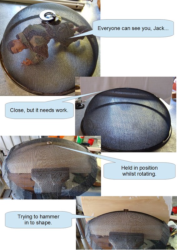
On getting it into the shed, it was the perfect size, & pretty close to the shape I wanted.

I figured that I could use the wooden parabola cut-outs I had made to help form it's shape, then impregnate it with some modelling clay, then when it hardened, sand & coat with reflective material to finish it.

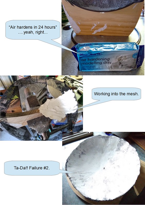
Well, it didn't work out so well. The clay did not harden, & the mesh did not hold it's shape very well.

This could be useable if it eventually hardens, but I am moving on to attempt #3.

____________

Reflector, part 3

8th August

In my search for a reflector, I came across some information that appealed to me; if you spin a fluid-filled container, a parabola will be formed on the surface of the fluid. This "spin casting" method has been used for quite some time, particularly for larger applications.

I designed a jig, using a length of tubing sandwiched between a couple of heavy duty roller bearings, with a bolt running through the center. The bolt attaches to a solid plate (the turn-table) at one end, & is driven by a drill at the other end.

The assembly is clamped in a vice, & leveled with a spirit level;

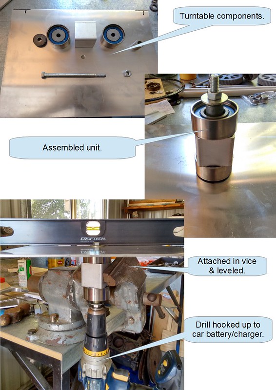
The cordless drill was hooked up to a car battery & charger, as the drill speed has to be consistent throughout the operation. I also used a zip-tie around the drill trigger to gradually dial up to the required speed.

Of course, Jack had to have the first test-drive;

....& then I had to clean up Jack's lunch off the turn table...

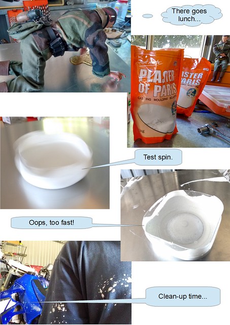
"Plaster of Paris" was the choice, & after creating a mess experimenting with the viscosity in a smaller jar, it was time to move up to full scale.

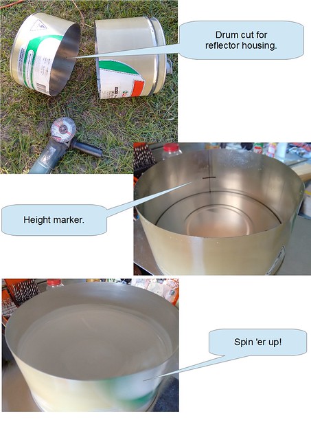
I sectioned a 20 liter oil drum, cleaned up the edge, then centered it on the turn table, & marked out a rough guide for the height of the edge of the reflector.

The first two attempts were a learning curve, which ultimately ended up in the bucket, & resulted in another trip to the Dollar Store for more plaster...

I had to mix the plaster a lot thinner than I thought, not only to give me more working time, but to allow the parabola to form completely.

The butter-zone was about 95 rpm, & the drill speed was locked in again with a zip-tie around the trigger. I let it go for about three hours, which gave me time to clean up the mess, & do a few odd jobs, whilst keeping an eye on things.

Well, I think the third attempt has turned out alright - I'll find out tomorrow morning after it's set overnight.

Fingers crossed for tomorrow!

tbc...

---------------

9th August


Well, everything is looking pretty good. The surface of the plaster had a fine layer of powder on it, which dusted off with a light brush.

The plaster still was not fully set, & the surface was easily scratched, so I left it out in the sun for the day;

In the afternoon, I hit it with a few coats of matt black paint. The first couple of coats were absorbed into the plaster. I later hit it with a few more coats & finished it off with a coat of clear polyurethane to seal it.

I will be using an adhesive mirror sheet to coat the surface later in the build.

The reflector turned out to be a mammoth effort, but I'm happy with the outcome now.

-------------------

Reflector, part 3.5


16th August


Remember the red bucket from a few pics above?

Well, it's now a little heavier...

And why is it heavier?

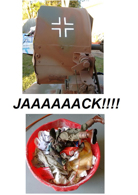
Yes, that's "reflector #3" sitting in there, albeit in pieces after Jack's little party he had last night....

Seems Jack invited his old war buddy "Gef" over to check out the light, & he brought a few, ahem, ladies, over with him.

Well, after the mess they left in the reflector, the paint started to flake off when I went to stick the reflective coating to it.

Note to self; nothing really sticks to plaster.

I still had the turntable I made, so I set it back up, but this time, we have a new kid in town;

No, not the self raising flour.... It's "Bondcrete". The best I could describe it, is it's like the old white wood glue.

Unfortunately, It takes quite some time to cure, but if it turns out like the spilt blob on the store shelf, it should work well.

It's been spinning now for 14 hours, & I'll leave it go for the rest of the day....


--------------------


Reflector, part 4.


22nd August


Last night, I stopped the turntable.
Yes, the Bondcrete had been spinning all week. Approx. 601,920 turns.

Had it set? Nowhere near it....

A thick skin had formed, but inside, it was as runny as the day I poured it in.

I punctured it, & drained what I could salvage back into the container... The skin was peeled off, & thrown into the familiar red bucket.

I kind of knew it wasn't going to work after the first couple of days, so I had ordered some casting resin from a local seller. Luckily it turned up on Friday.

After cleaning out the drum once again, I prepped the resin.


This was my last shot. I knew I'd only get one go with the resin.

I spun it up, this time a little slower, so the focal length was a bit further away from the surface. I tested by shining into the spinning liquid, & noting the reflection on the roof of the shed.

I then poured the catalyst in, & mixed it through whilst it was still spinning.

I left it spin for a couple of hours until I was sure it was set, then let it sit overnight.


23rd August

This morning, I removed the casting from the drum. It had shrunk slightly during the curing process, so was easy to get out.

Prior to removing it, I drilled several holes through the bottom of the drum & into the reflector base, so it could be fixed back in place with some screws after I had applied the mirror coating.

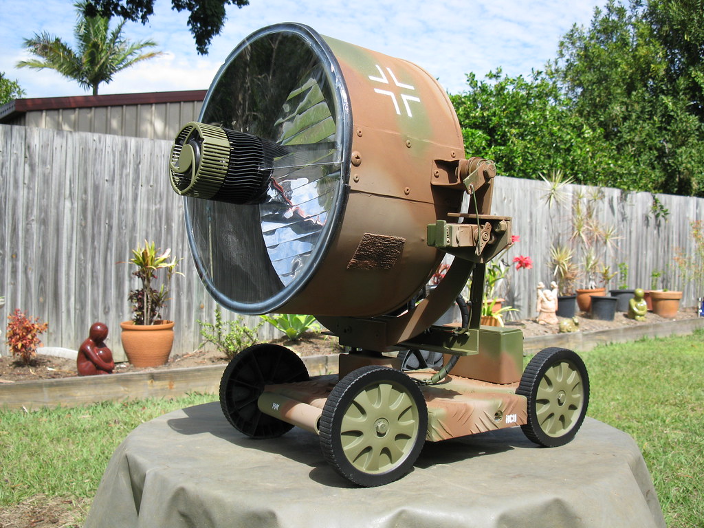
The mirror coating I had was in 15cm square sheets, & due to the shape of the reflector, I had to cut them into thin strips to get them to conform to the surface.

Although the mirror sheet had an adhesive backing, I felt it was not strong enough, so I took it all back off, & applied contact adhesive spray for a stronger bond.

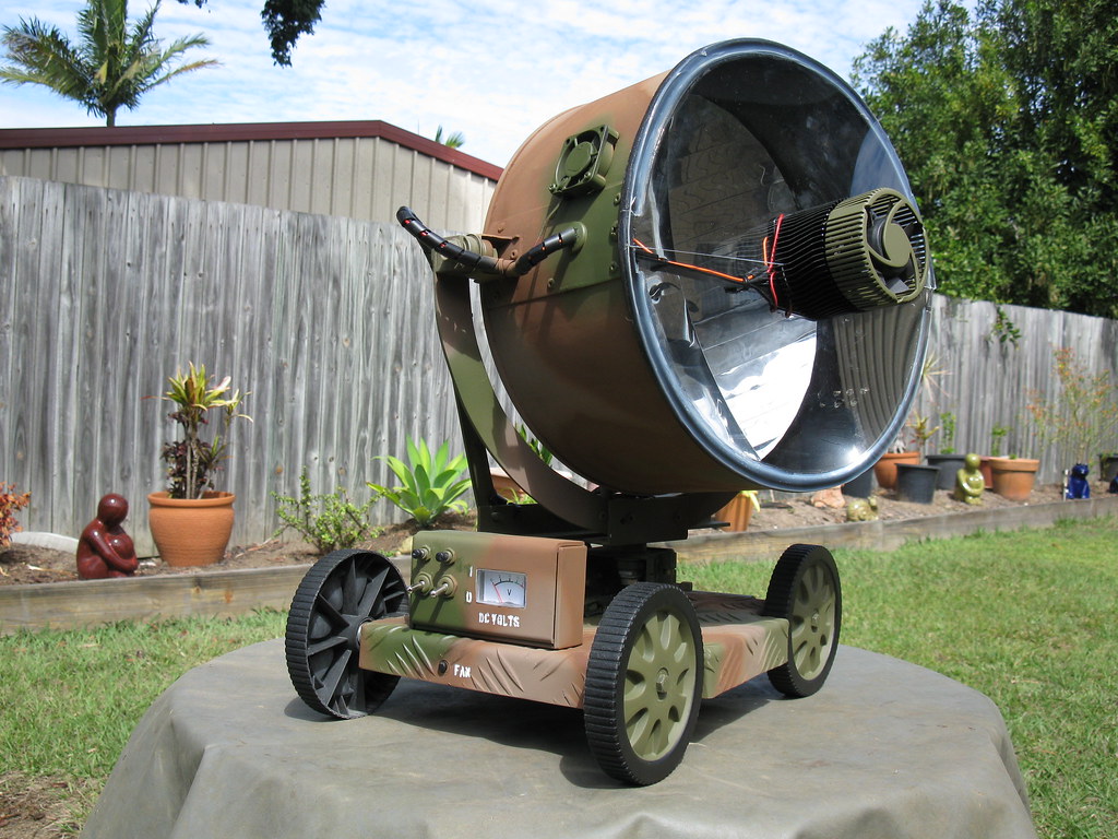
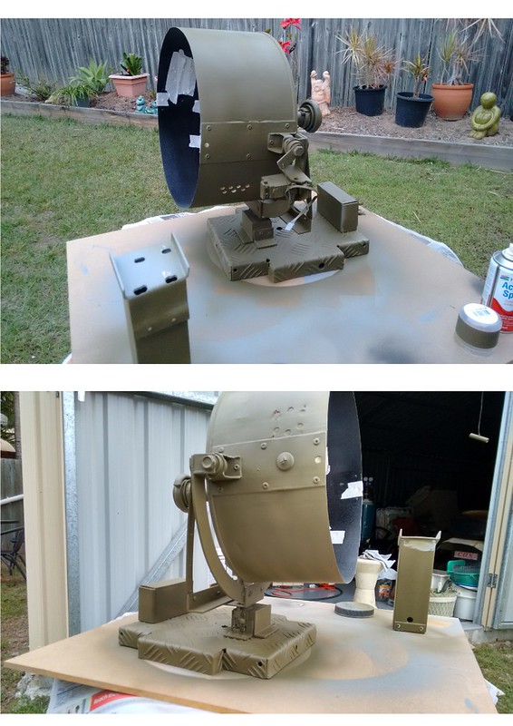
The drum was cleaned up & re-painted inside, & the reflector re-installed.

Like myself, some of you might be wondering; "I wonder if it will burn stuff?"

As you can see by the reflection, it's a cloudy, overcast day, so I had to wait for the sun to poke it's head out...

https://www.youtube.com/embed/HKZ3rVDaGSU

Yes, it does burn stuff, with ease!

-----------------------

Trailer

(19th July)

The trailer/carriage assembly will be the backbone of the build. It needs to be reasonably strong, but light enough to be carried.

When completed, it will be able to be carried via a handle, & also have a hook so it can be hung up as a lantern.

I'd been eyeing off a spare laundry cart for a while, as the wheels were about the right proportion for the build, & I can utilize the metal frame as well.

I started out today by disassembling the cart.

Jack offered to take the parts over to the workshop, & start mocking up the frame.

Half an hour later I stuck my head in, only to find him goofing off.....


--------------


(30th August)


Seeing as I have a decent selection of alloy due to multiple raids on the neighbor's scrap bin, I set about designing a uni-body chassis that I could fold from a sheet of checker-plate.

I stuck some paper to the underside to help draw out the dimensions, then started cutting the sheet.


I then folded the skirts & wheel cut-outs in the vice, using a hammer & some wood.


I had a re-think on the battery cradles, & decided to attach them to the underside individually, using machine screws threaded into the body plate.

The main control box & turret footings were also marked out, ready for attaching.


Once installed, the turret mount was strengthened with some angle stock.

Apart from mounting the wheels, the main chassis & components are almost done.


----------------


Light Engine

(1st August)

A lot of stuff turned up during the week, including the parts for the light engine.

Up until now, the heat sink I'm using was my LED bench tester. It has a large chunk of solid copper which is finned at the rear, pressed into an alloy ring of cooling fins. I also managed to locate the original high-speed noise maker fan that it came with.

The fan will be switched on automatically by a bi-metal disc temperature switch, which is mounted on the inside of the cooler. The temp. switches were inexpensive, so I bought several with different switching temps. I've installed a 45DegC switch to start with, but can swap it out easy enough if I find i want a higher switching temp.

On the business side, we have four XHP 70's. The stars will be held down by a clamp arrangement in the center, & a screw on the outside. I used some dummy stars during the drilling & tapping to avoid any damage to the XHP's.

I filed down the corners to neaten it up, & also to reduce shrouding of the reflected light.

Jack popped in to lend a hand with his over-sized tap....

I may put in a couple of additional holes in the outer alloy rim to thread the wiring through, & the copper face will be lapped prior to final assembly.

The outer holes have been pre-drilled for the mounting arm/beam that will hold the assembly above the reflector.

---------------

(29th August)

I changed the clamping arrangement for the LED's, as I will now be using two separate drivers. The single plate I had previously would have connected all of the - pads.

I made a pair of mounting arms from a strip of flat alloy, that will suspend the light engine over the reflector. The end brackets are slotted, to give some tune-ability for the focus.

With the light engine mounted, I started on the lens assembly.

First, I cut a slit along a length of rubber hose, & fed it onto the lip of the drum. The hose is in two pieces, & will be attached to the two lens halves, making for a removable lens assembly.

For the lens, I'm using two sheets of perspex that will butt up against each other in the middle.

I cut out a half-circle on each sheet to clear the heat-sink, then marked out the perimeter.

With the sheets cut to size, I ran a bead of silicone sealer on the top of the rubber hose, then put the perspex in place, & turned the whole assembly upside down onto a bucket (no, not the red bucket...), & let it sit over night to dry.

By morning, the silicone had set, & the perspex was attached to the rubber hose. The excess silicone on the inside will be trimmed off later.

There is enough movement/flex in the lens & rubber hose to allow for focus tuning.

------------------

Fixings, Mounts, etc.


10th August.

I began work on the pan & tilt mechanisms, which will eventually be operated by a separate control unit that plugs into the trailer.

Strips were cut out from the discarded part of the drum, & attached to either side of the reflector assembly to strengthen the mounting area.

I worked out roughly where the center of gravity was for the reflector assembly, then fabricated some brackets to house the roller bearings. The square tubing I had was just too small for the inner bearing to fit, but I was able to bow the sides of the tubing a little in the vice to coax them in.


I attached the brackets with a rivet, then welded the base to the lip of the drum.

With the brackets in place, I measured out the main mounting plate, & cut it out from a thick sheet of alloy.

After setting up the bearings & tweaking the brackets for clearance, the reflector assembly was mounted. Check it out!! :D

__________


15th August.

The metal fabrication shop that is across from where I work was doing a lot of alloy work during the week, so I was able to get a good supply of off-cuts :)

I started today by making a turret base to mount the reflector assembly on, & added some braces to re-enforce the assembly.

The turret will be operated by a servo motor, which will be hiding on the underside of the body platform.

A housing for the servo was fashioned out of some rectangular tubing.


The turret is mounted to the housing by a bolt(the axle), that goes through two roller bearings that clamp to the housing.

The servo will drive the turret axle via a fork arrangement that I made from a piece of angle off-cut.

I also made a start on the battery cradle, which will be attached to the underside of the body as well.

I sectioned a square tube that had the perfect height to house both battery trays. The trays will slide out for access to the cells.


I also started on the main control panel, which will be mounted on the body.

A window was cut for the voltage display, & hole drilled for the power switch.

The panel will also be equipped with momentary buttons to control the drivers.


-----------------


30th August.


I originally thought I would be using only one driver for the four LED's, but that didn't work out.

The control box was re-configured for two drivers, & a momentary switch was installed for each one.

I used a piece of C-channel to form a box around the control panel.


The panel fascia is attached to the enclosure by two recessed machine screws, to allow access to the electronics.


It's now ready to attach to the trailer body.

There will also be a remote control unit to operate the servos. It will be plugged into the trailer via an extension cord.

The batteries that power the servos will be housed inside the remote pedestal unit.


The servo controllers have three functions;

* Manual control.

* Automatic sweep.

* Return to center.


I bent up another piece of C-channel for the top, & cut holes for the wiring connectors.


Seeing as he will be operating it, I thought I better get Jack over to get used to the controls....


----------------


5th September.

Instead of using a "draw bar" as the carry handle, & having it protruding out the front, I designed a retractable handle.


A spring keeps the handle flush against the body when not in use, but allows the handle to extend under the weight of the light.

It was easy to make, & works quite well. The slotted hole allows the light to be hung from a hook or nail as well.


I also spent a bit of time getting around a problem Jack created when the reflector was changed from plaster to the resin;

The center of gravity had changed quite a bit, as the resin reflector was shallower, thus lighter, & the focal point was further away, so the light engine was further out.

As the reflector assembly was no longer balanced at the pivot points, the servo was having a hard time lifting it.

Originally, I had the servo working directly on the pivot axle, with the same fork arrangement as the turret pivot. After a bit of head-scratching, I managed to re-locate the servo, & used a lever mechanism to gain a mechanical advantage.


It still was not quite good enough, but Jack assured me that he could sort it out, using what he described as a "Stealth Inverter Pendulum Assembly". He says the details are classified, but to me it just looks like a lump of lead on the end of a pole....

He had me weld some brackets to the housing & install a cross-bar, then I let him do his thing;


Whatever it is, it got the job done!

To prevent the servos being stressed when the light is being transported, I installed locking bolts which hold the reflector assembly in place. These will also be used when the remote control unit is not attached.

As the reflector housing is relatively sealed, I figured that it will get fairly toasty inside, especially on higher output settings, so whilst I was in a drilling mood, I mounted an extraction fan on one side, & placed vent holes on the opposite wall.

That's pretty much it for the body & fittings now - I'll be moving on to the wiring & paint stage next!


------------------------------

-----------


Electrics, wiring, & paint.


6th September.


After earlier unsuccessfully trying to modify a single FET driver to run all four of the XHP 70's, I had settled on running two separate drivers.

I used two MTN-17DD boards, & populated them with components for the Zener configuration, to suit the 6 volt XHP's. The boards were then flashed with STAR Momentary firmware, & bench tested.

I have wired them to operate individually, so there is two channels, giving the option of running either two or four LED's.

The analogue voltmeter is wired so it will display the battery pack voltage when either channel is powered on.

With the control box wired up, I made a plastic insulator shroud that is epoxied in place, prior to re-attaching the controls to the body.

Back outside, I had already started painting some of the smaller components. The old trolley wheels were cleaned up, & given a new lease on life.

After the control box was re-fitted to the body, the whole assembly was cleaned down & taped up, & given a coat of primer;

Not long after, the first coat of "Olive Drab" was applied;

------------------------

12th September.


Before I could get too carried away with the paint, I had to sort out the remainder of the wiring.

Below is the wiring layout on the underside of the body. The R.C.U. connector will be epoxied to the body, & accessible through the hole in the side.

The thermal switch & LED's were re-attached & wired up. I took power for the fan from one of the Sinkpads.

For the R.C.U. connector, I cannibalized an old VGA card that I had been saving for the historical society....

Jack turned up to lend a hand, & got the main harness finished off. He did a pretty good job, & everything was looking good for a test-run. I slid in just four tame laptop pulls that were on about 4.02v for the initial test, & flicked on one of the switches;

The volt meter sprung to life, & there was no magic smoke to be seen!

I ran it through the modes, & then tested with the 2nd channel, & finally both channels together.

The beam has four hot-spots, which I knew would be the case, as I had earlier shined my 5*SRK into the reflector, & got 5 distinct spots.

I waited until night, & with the same four cells, now at 3.9v, I fired it up for a few teaser shots;

Well, it's pretty bright even with four tame cells in it. I wonder what 8*25r's will do...

The four hotspots are pretty obvious at a distance, but short-medium range they blend together for a massive hotspot.

I'm almost inclined to just run with one emitter, but it's too late in the build to think about that now.


13th September.

Today is paint-day, & I have Jack on-board again to help out.

Everything was masked up & prepped, & Jack installed a filter for the vent holes on the side.

....looks like Jack's buddies have come along to help out as well!

..... hang on, I think that's "Geff"....what's he doing back??

...& who is that guy?? He looks pretty serious.... I heard him yelling at the others in German!....

Well, I thought it might be time for a lunch break... Pretty soon, the other guys left. Jack wasn't saying much either...

After a bite to eat, the camouflage layers were laid on with an air brush;

While the paint was going on, Jack prepped some stencils for the controls & connectors;

Jack had continued to apply the markings whilst I washed up after painting;

Hold on!! What's that??!!

Ok, now I know what Jack's little gang had in mind.... I reckon they were going to steal it for their "Manneshöhle"!!

Well, that's the last time we're going to see Jack....


Regardless of Jack's livery, I think it came up looking pretty good. I put the wheels on, & took a couple more photos;

There's still a few things to finish off; the lens has to be fitted, & the R.C.U. needs a couple of details added.

It should be completed next weekend, along with a few more action shots, & some video of it working.

-----------

19th September.


This morning, I was eager to get the light finished.

As I entered the shed, I could hear a faint high pitched noise; it was coming from the light. At first, I thought I'd left it powered up, but no, it was off...

On closer inspection, the noise seemed to be coming from Jack's Stealth Inverter Pendulum.

I took it off, & this is what I found.... Yep, he'd planted a tracking bug...

I got rid of the Pendulum, & replaced it with an expansion spring..... geeez, what was I thinking..."Stealth Inverter Pendulum".....!?!?

With that sorted out, I put the finishing touches on the RCU, & installed the lens;

I was keen to test out the performance, & had charged up a set of 25r's;

Measured at 10m, I read 328k on one of the hot-spots, which works out to about 1145m throw. Not too bad, considering there's four of them.

I waited for nightfall to test the hot cells outside, & to check out the modes;

Hold on - is that Jack hiding in the bushes???

..that guy just doesn't give up....

----------

Well, that's it! Finished!

Here's a short video/photo collage I put together for a little atmosphere, & to round up the build process. I'll put it up in the OP, as well some final pictures.

Thanks for watching, hope you enjoyed the build! :beer:

----------------------

Subscribed :slight_smile:

Oh my, this sounds real interesting.

This is going to be amazing :slight_smile:

The reservation has been accepted. I love a bit of danger.

WWII Battlefield Searchlight - Sounds great! I'll get my old helmet out in case I need to hit the trenches.

I’ll use the OP for any brainstorming from the BLF community.

1st round of brainstorming is now open…. :slight_smile:

l'll be back to help after I've finished with slayin the hooded zombies.

All I can say is “Who’s hand is this supposed to be held in and what are they holding, the remote for the motor driven carriage?” Gonna be bright even if it blows the rules into orbit. Another category might be needed beyond man portable such as “rail portable”

I'll be sure to put a handle on it ;)

... & How did you know about the remote??

I figured you’d at least have a rope to tow it. That counts as a remote, right?

Tow what? The light, or the generator unit....

No, to whit, not tow what.

Ahhh, that clears it up then :) :beer:

I went for a drive earlier, & noticed all of these nice satellite dishes on people's roofs. They look exactly like what I need, but the're about twice the size....