The "not a contest" Contest, but not in the contest, since we both will break the rules and these are really lights for the contest winners.
08/25/15 - Finished
07/22/15 - Look towards the bottom of the post. New stuff done...
07/11/15 - Well, the first attempt was a big flop. I tossed the body assembly. I will have to buy new lights and come up with something else if I can figure out something. For now, it's on hold till I find a job. Can't put any more into it right now. I will figure out something. There's plenty of time, right?
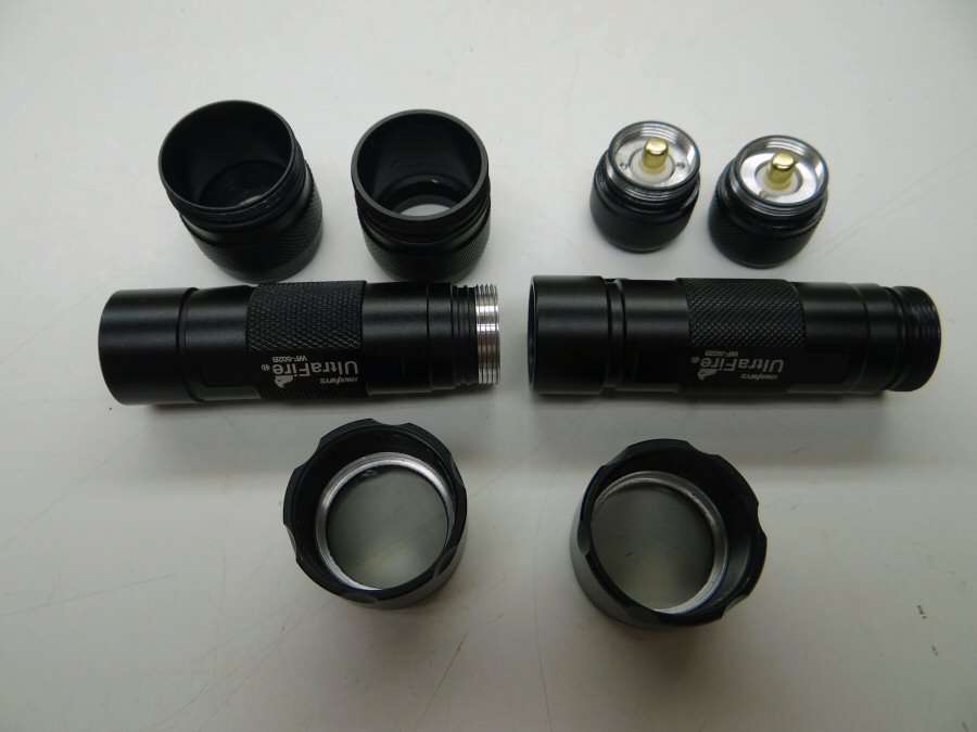
At least I give you photos... Two junky, but new, 502b flashlights. You ought to know by now, I love XHP70 leds, so this one will be no exception.
I need to put the two bodies together so I can run 2x18650 in series.
I need to make some kind of bigger head that will have cooling fins. As far as hand work goes, I'm semi-retired and mostly very tired, so I won't be making finned heads by hand. I'm gonna Cheat!!
You can see what I decided on. This is a cooling heat, or heat sink for a Nitro RC truck motor. I will be fitting the 502B head into this, to give some mega cooling and to make it look unique. It will be repainted with some crazy color yet to be determined.
--------------------------------------------------------------------------------------------
This section doesn't apply any more. It was a flop.
07/09/15 - I really wasn't going to post, but I saw RBD took the lead by posting some of the materials he is going to use. Well, I have to follow suit, don't I?
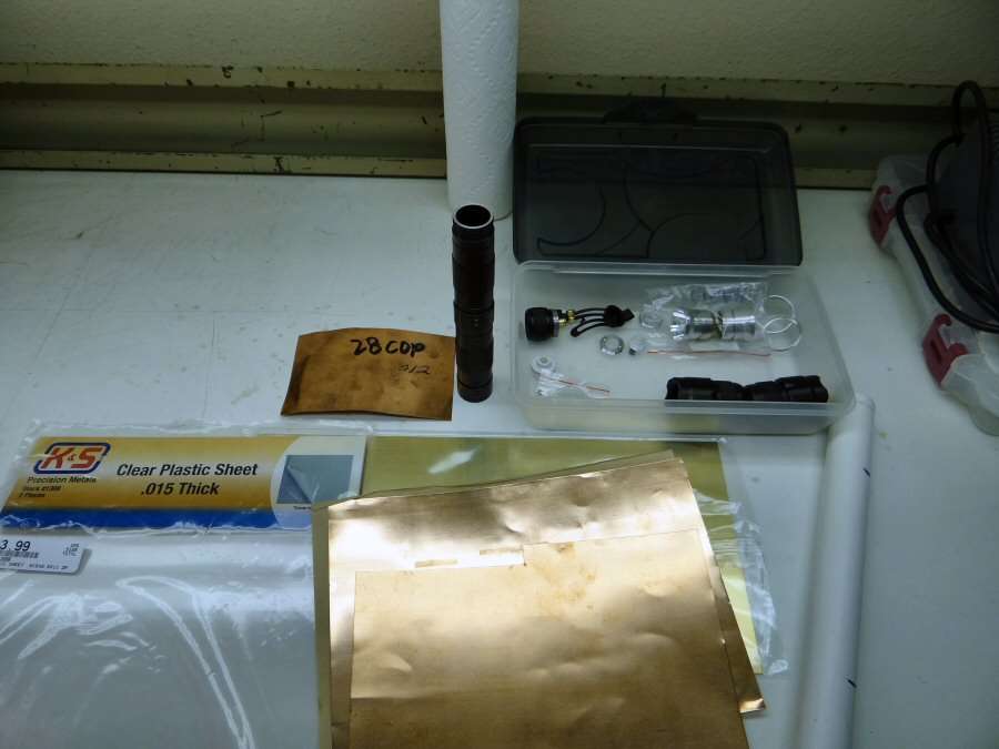
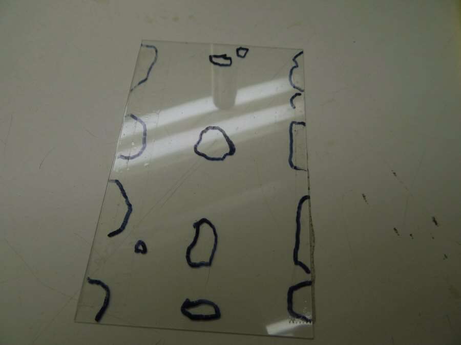
I have already stripped the lights down and I have already put together the two bodies. I did that by opening up the tail end of one and removing some of the OD on the front end of the other. Basically, I removed the threads on both, just enough to make it a press fit. That and a little JB Weld will keep it together for good. The light doesn't show color correctly, but there is Copper sheet there and Brass sheet there. I wonder what I will be doing with that? The plastic sheet is for tracing and making templates.
Here's a hint and a little incentive for the duck. I know his creative juices start flowing when there's some incentive.

Or,

I don't know if the cut out will show the brass below or if the cut out will end up being blacked over. Time will tell.
That's all for now ----------------------------------------------------
07/11/15 Back at it again.

Things do not always go as you envision them. From idea, to implementation is often a struggle. I wanted to wrap the brass around the body as a sleeve. I had to heat the brass, to soften it, (annealing), to be able to form it and it was still hard to do. I used a bunch of pieces of wire, wrapped around it, to hold it while soldering it together. The result was less than spectacular because of the bodies. They had high and low spots so the wire would deform the brass. The result was something that would not work, so I used JB weld, to fill in the low spots. After sanding off the excess, I took my flames pattern and saw that I could still make it work, if I fit them in between the areas covered in JB weld.
I made a plastic template showing the bad spots and fit the flames around them. The bad spots will be covered with Copper, so no one will know. Well, you already know...
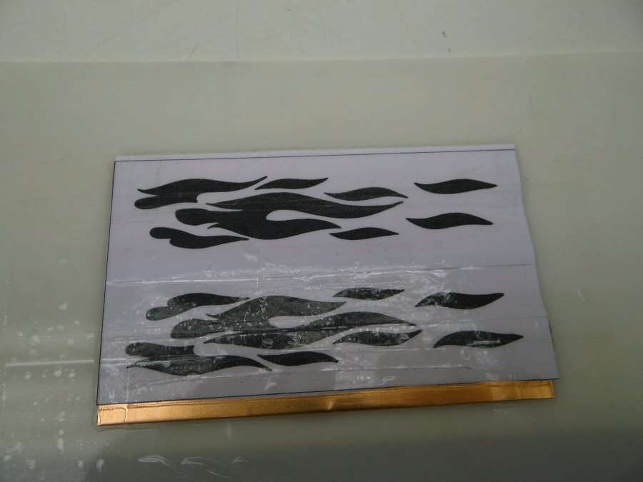
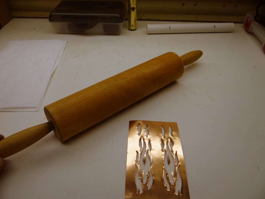
I taped the flames patterns onto a piece of 0.005" thick Copper sheet and onto a plastic backing. Then I started cutting out the pattern with an X-acto blade.
I tried to cut deep enough to leave an impression in the Copper, so I could remove the black areas and still have the rest to help finish the cuts, to remove the Copper in the exposed areas.

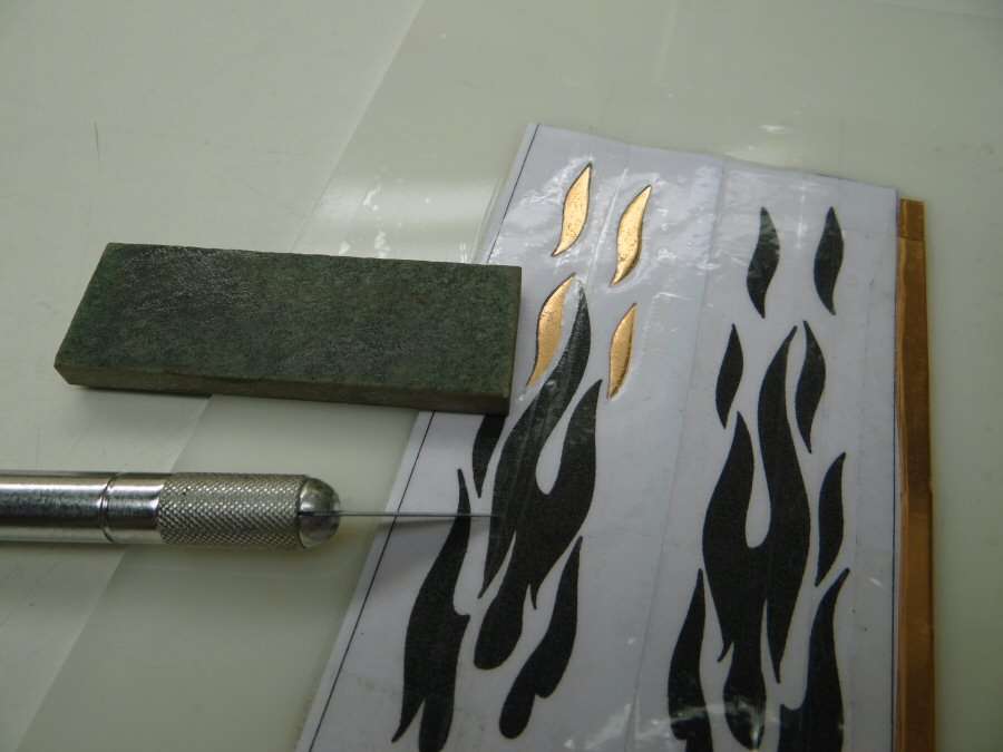
I'm still working on it. It is amazing how much pressure is needed to cut through a measly .005" Copper sheet. The X-acto blade tends to break off at the tip. They always do, so I keep one of my sharpening stones handy, to dress the blade. I have to do that for every piece cut out. The blade dulls that fast. It's been a couple of hours and getting too hot already, so, time to take a break.
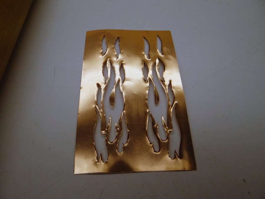
I got the pattern cut out. It's not too good. Cutting makes the edges curl up, so I got out the old rolling pin and gave it a few swipes with that.
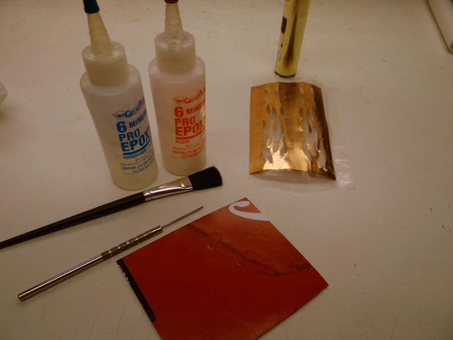
It came out fairly smooth and I hit a few edges with a small diamond file. Then I covered it with heavy clear tape and I mixed up some two part epoxy. I used a small brush, to coat the back side and rolled it onto the brass. I used 6 minute epoxy because I knew I would have to hold and roll the part while the epoxy set and quick set makes that much easier, you just have to be fast.

In a couple minutes, I will take the tape off and clamp a piece of leather and wood against the seam and leave it set for a few hours.
I do not think this is going to be pretty. In fact, I know it won't, but I will be painting the cut out areas with black paint and I can clean up the outer copper with 1500 grit paper and steel wool. Hopefully, it will be "good enough", although I can't remember making anything that was "good enough" in my judgment.
--------------------------------------------------------------------------------------------------
07/22/15 - So, I had to get a couple more lights and I'm back in business. I have been hitting the shop early in the morning, for a couple hours a day and I've gotten the head assembly figured out.

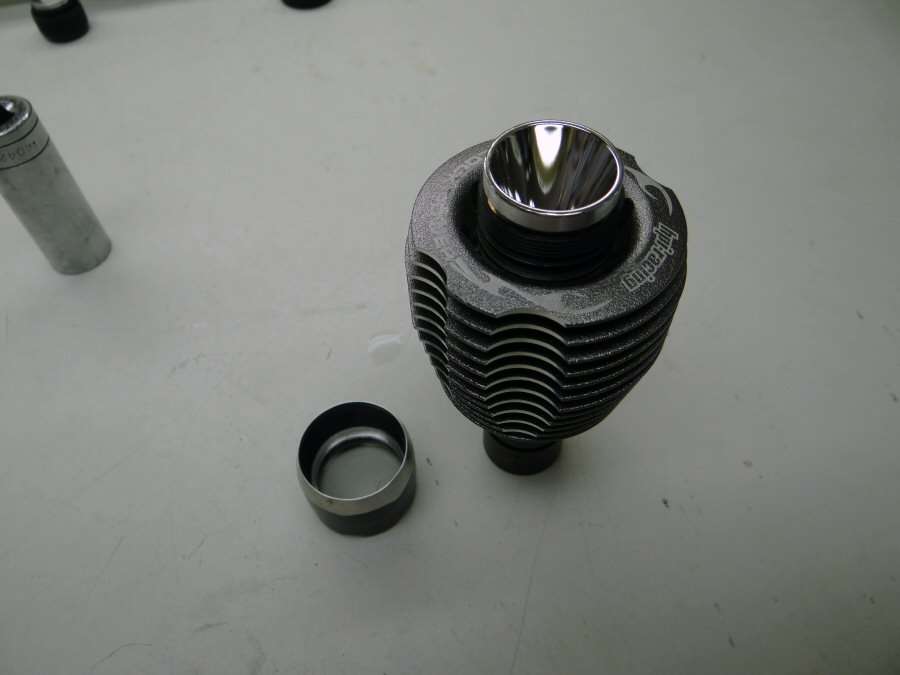
OK, I have the parts all milled, so I can begin assembly, but I will go through the steps to get there, so you can get an idea of it.
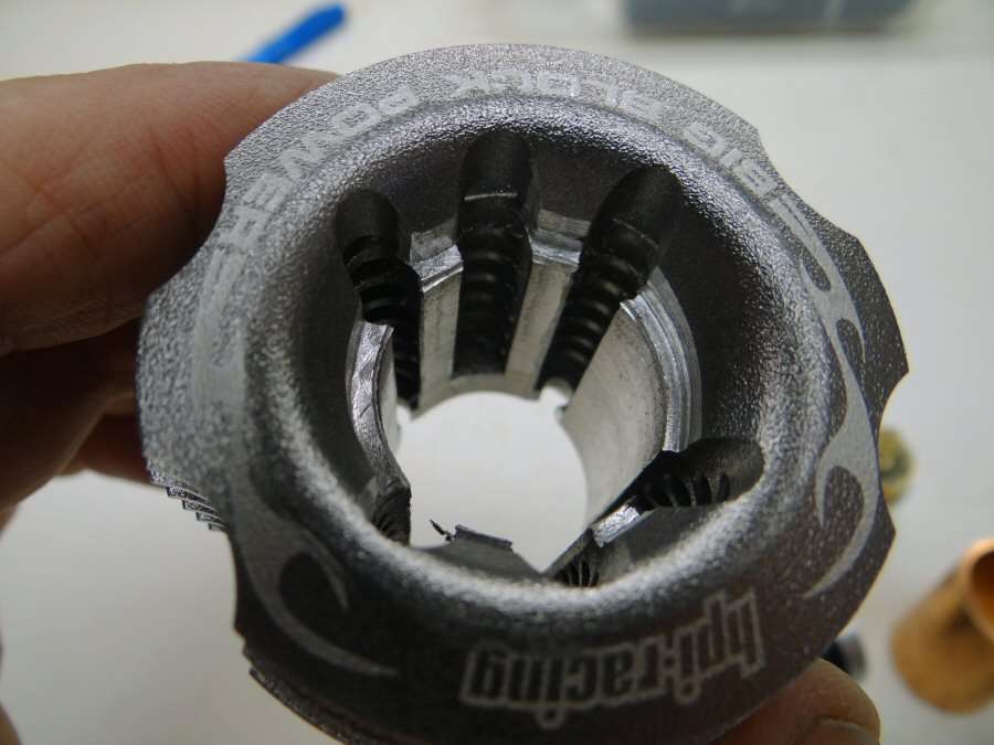
First of all, the RC cooling head was bored out, so that a 3/4" copper coupling would go through it. Also, at the very top, I stepped it a little larger, for part of the 502B head to sit into it a little. This was all done with the drill press and a router bit.
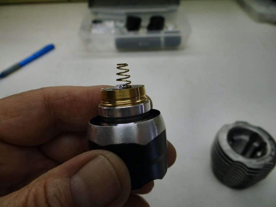
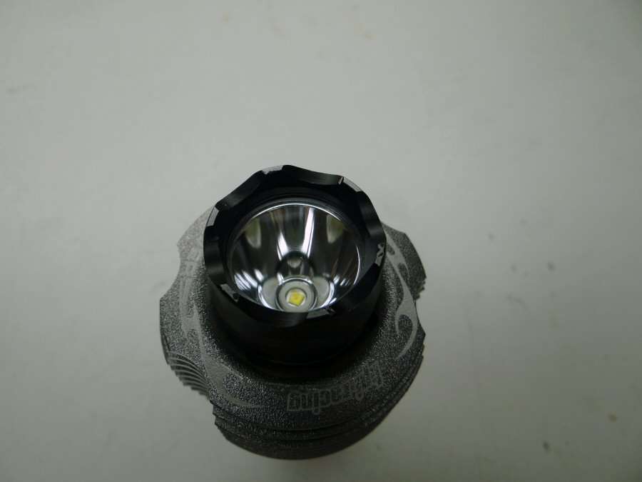
The 502B head is in two sections. The bottom section allows the body to screw into it and it also screws into the top of the head, which we would normally call the bezel. I cut this piece in two because I only want the section that screws into the bezel. The copper coupling will be going right into this section of the head, as you will see in a minute.
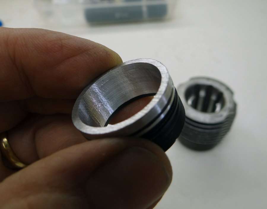
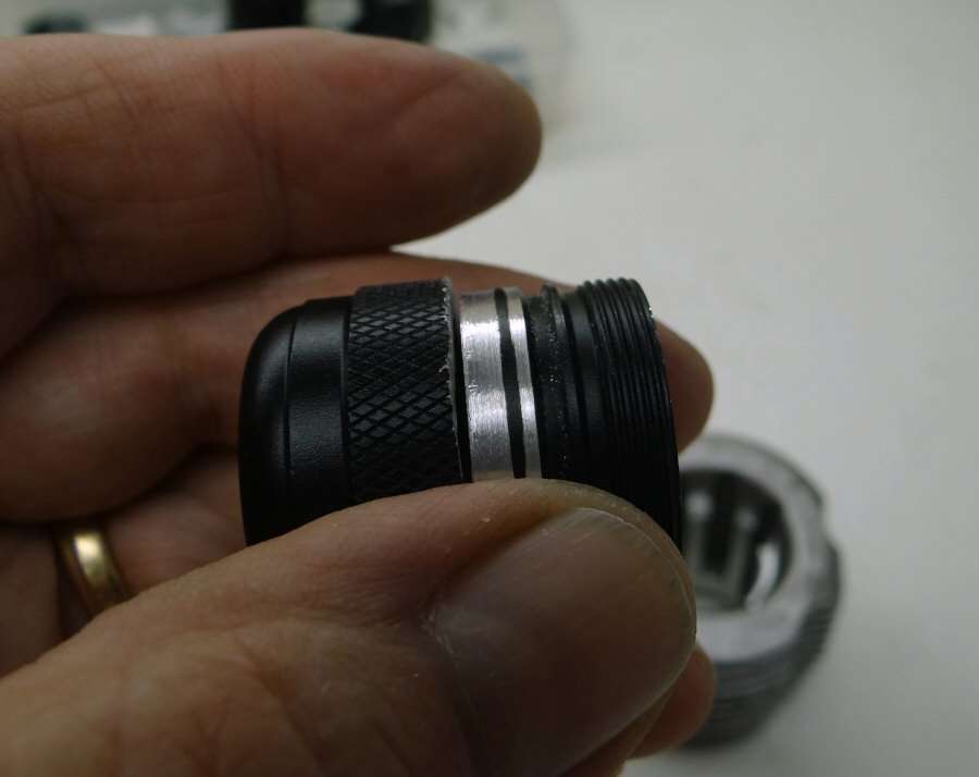
The threaded end goes into the bezel. The inside is bored out so that a 3/4" coupling will press fit into it. The bare aluminum on the outside is where I removed a little material, so this part will fit into the top of that RC head, where I made the larger step on top.
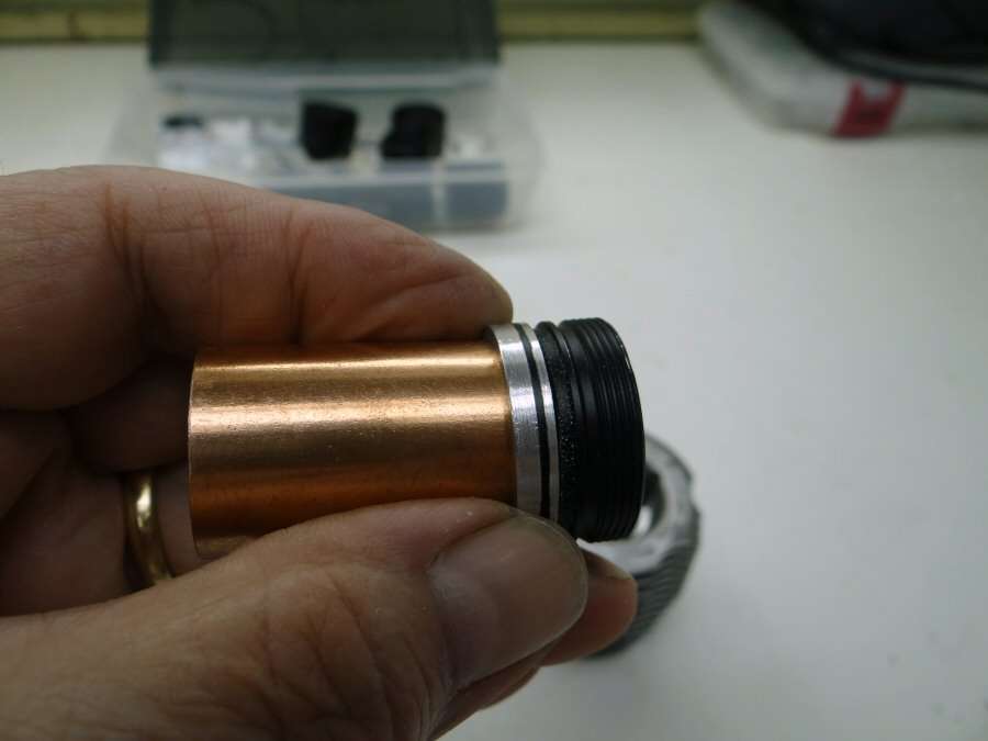
The coupling will go all the way inside this section of the head and when it is screwed together, the coupling slides over the back of the reflector and actually seats against the reflector from behind, holding it tight and giving some thermal transfer there.
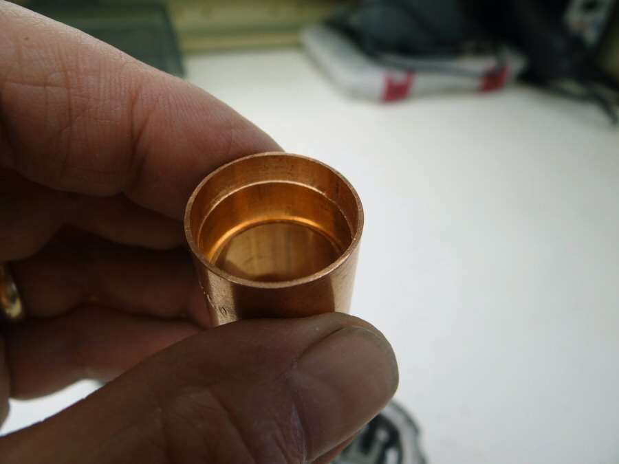
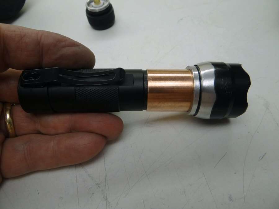
The other end of the 3/4" coupling has been bored out so that the body will press fit into it. I will be using JB weld too, so it will not come apart.
You can see how the body will press in.
The bezel also gets a little work. I have tapered it, so that it will fit down in the tapered top of the RC head.

Inside, there will also be a short piece of 3/4" pipe that will slide in and press against the brass pill, to hold it tight and give some thermal transfer there. I do not plan on potting it, but I might have to. I want to be able to take the pill and reflector out if need be and potting is more permanent. Time will tell...
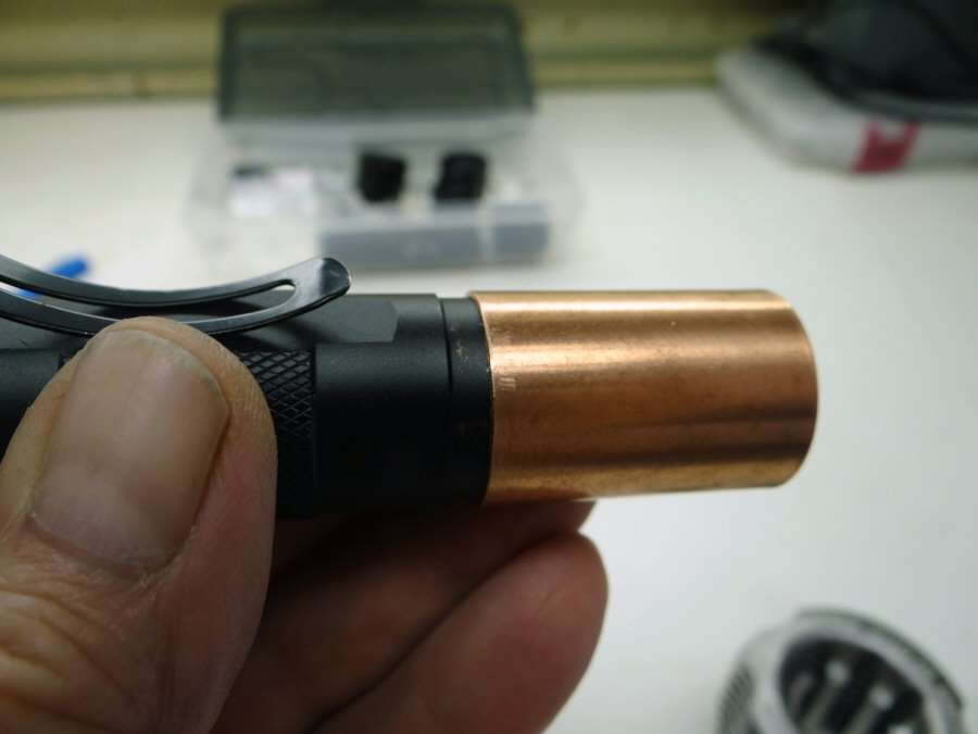
Kindasorta how it goes together. The copper and the head will go in the RC head from the front, press fit, and then the body will go in from the back.
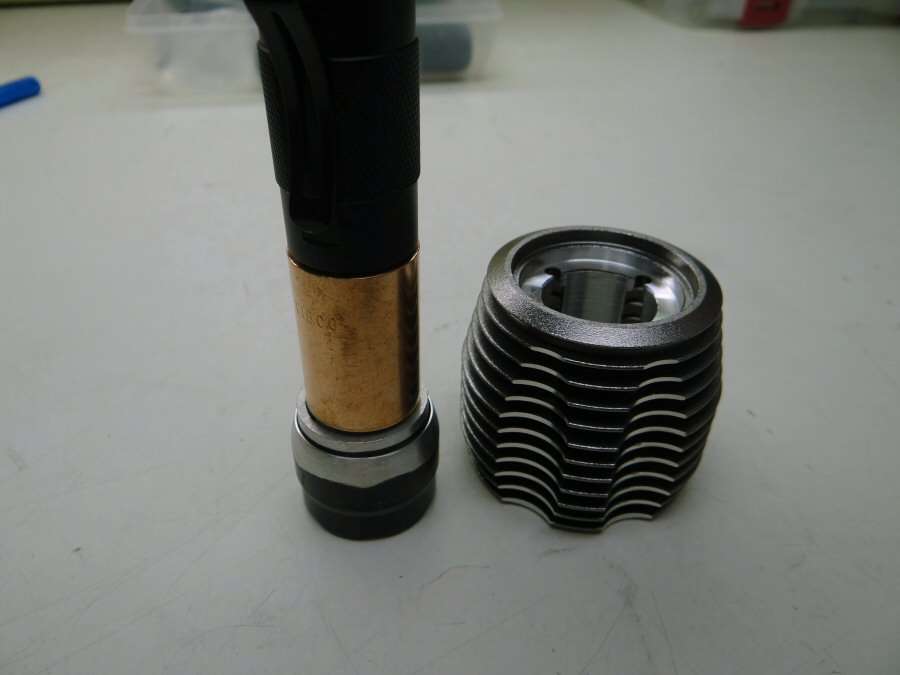
Like this.
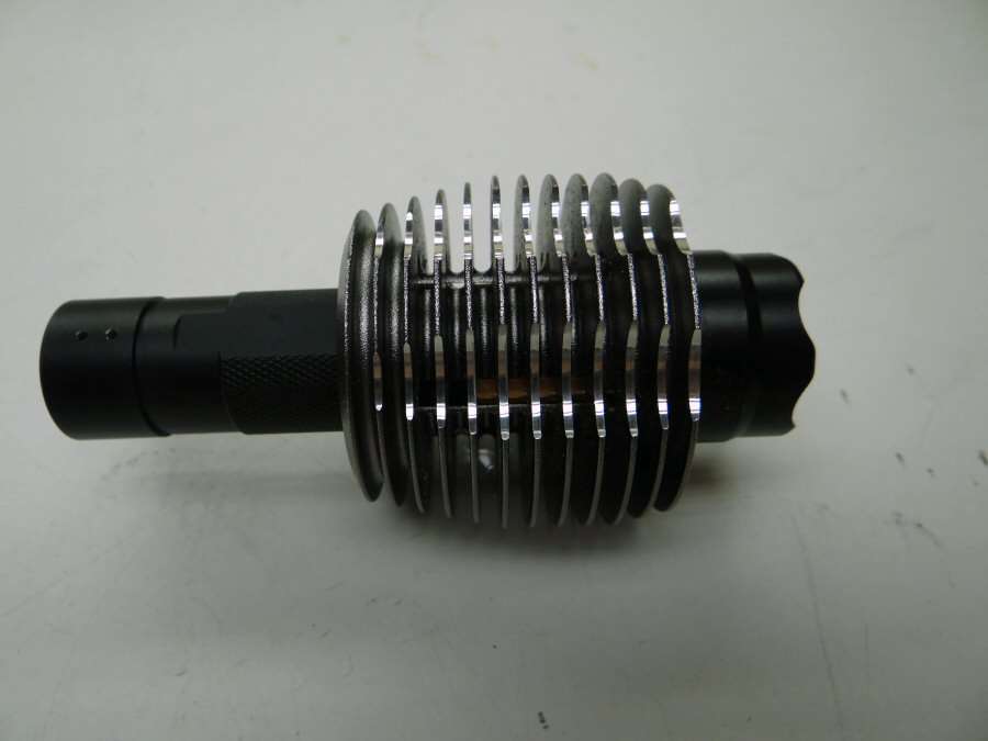
And like this!
From the top.
And the bezel still unscrews to be able to take the reflector and pill out. This whole light will be painted. I have not decided yet, but some paint from the automotive store. Something wild I think.
That's all for now. I still have a ways to go. I have to make two bodies together again and all that stuff.
-------------------------------------------------------------------------------------------------------------------

Painting is finished. The Orange didn't show up well with this POS camera. Both colors have just a little metal flake in them.
-------------------------------------------------------------------------------
08/25/15
Not a lot to say. The light is finished. The pill has an XHP70 led on a 16mm copper mcpcb with a 17mm FET driver from RMM.
On high, with two Efest cells, it pulls 6.75 amps at the tail cap. Respectable for a 502B. The press fit copper components do their job. The finned head gets hot fast, so transfer from the pill is good.


The reflector is more like a matte finish, than stippled. It makes the beam smooth, but large. No spotlight here, just a bright flooder.
Five modes...
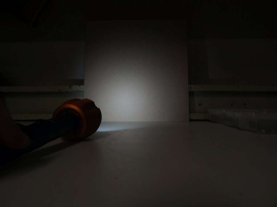

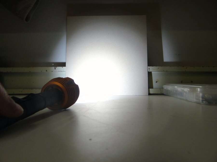
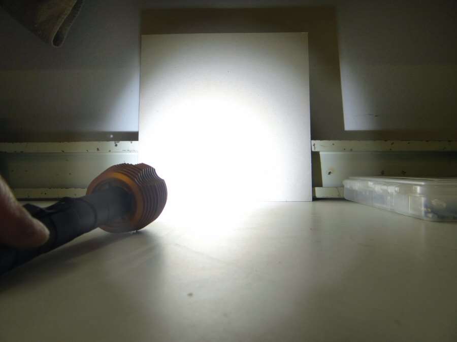
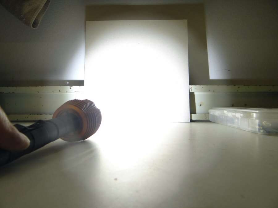
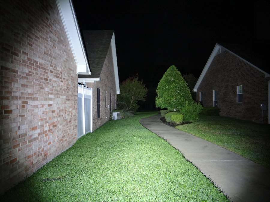
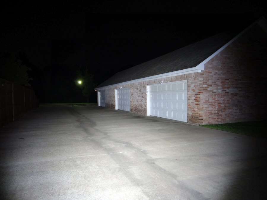
I took the shutter speed up to 1/60th, to get an idea of the beam without blinding the sensor and washing it out. Maybe I will get some night beam shots of it some evening.
-----------------------------------------------------------------------------------------------
That's all folks. Ready and waiting for some contestant to receive it.