BLF A6 FET+7135 Light Troubleshooting and Mod thread

I spoke with bugsy36 about opening this thread to keep the original g.b. thread clear of questions and answers. Somewhere the op could be edited over time to include some basic flashlight operation, overview/troubleshooting and some mods and pictures. Of course I agree the darn thing should work when it reaches your door. :open_mouth: But this will give some beginners (myself included) a chance to learn. Let’s do our best not to trash this thread with rants. :wink: I will ask that this op be deleted if it becomes a place to knock the q.c. of our friends at the manufacturer.

bugsy36 also mentioned “If everyone remained helpful and positive it would show lots to the Chinese vendors and manufacturers and actually further our causes, wants, and of course needs.” 8)

That being said this will be a work in progress as all of your helpful suggestions and sweet mods :smiley: will end up here. Please if you think of anything from the gb thread that should be in this op let me know!

Please keep in mind my links to blf pages are for 30 comments per page settings.

  • TK’s infinite wisdom Everything she has compiled throughout the duration of the BLF a6 Group Buy. How the modes run through the driver, tint comparisons, paperclip mod :wink: , lumen output by mode.
  • ToyKeeper’s ui diagram
  • Runtime and mode lumens (rough estimate depends on battery and any mods) from toykeepers post in gb thread #1870

Mode group 1:
1: 0.45 lm / 2.66 mA / 39 days
2: 10.1 lm / 11.87 mA / 8.7 days
3: 64.5 lm / 139 mA / 18 hours
4: 187 lm / 385 mA ? / 6.5 hours
5: 417 lm / 1.48 A ? / 100 minutes
6: 798 lm / 2.96 A ? / 50 minutes
7: 1386 lm / 5.65 A ? / 26 minutes
Mode group 2:
1: 9.72 lm / 11.87 mA / 8.7 days
2: 139 lm / ? / ?
3: 578 lm / ? / ?
4: 1386 lm / 5.65 A ? / 26 minutes

  • Link for Samsung (Best battery for Lumen output) 30q Banggood 30q

Some beam shots from left to right: 1a, 3d, 5a. I kinda like having that desk in the pic because you can see what the tints do to natural objects. The 5a beam is probably the most accurate tint for the wood grain. Taken with a Nikon D3100 in auto seemed the most accurate but the 1a is probably not that blue to the eye.

  • I highly recommend checking this page out especially the “terminology” under “getting started” section for newcomers.
    Flashlight wiki
  • Okay I’m gonna throw this in here because I’m seeing that Banggood really is honest and highly appreciative of our business. I know that some people may disagree but at this point they are stuck in the middle of a q.c. battle that is not they’re fault. So let’s show them our gratefulness as they work to stock the second batch. Check this out of you want a deal on products. Aff and non aff for your consideration.
    M4D M4X deals - Astrolux WP1 and WP2 LEP

Some flashlight basics:

The negative power flowing through your light must run out of the led and board through the tube into the tail cap and then into the switch and up through the spring. Kind of like the negative of a car battery. So in effect you are “breaking” or cutting the negative when you push the switch. Your tube connects at the outer area of the tailcap (outer arrow). This is the spot where I think we had some doa’s. The switchboard connects to the tailcap and the retaining ring (the little brass part) and completes the circuit into the center of the board into the spring (inner arrow). So in effect with the tailcap off you can “short” or connect the negative from the battery to the tube. It just so happens that while doing some work on my light I had to tighten this retaining ring to get it to work. It stumped me for a minute but I had just “shorted” the tube and battery to check for function before I put the cap on so I knew something was up with the switch.

The other end of the light is a bit different. I’m still wondering if some tubes were backwards. You may notice that the threads near the pocket clip slot are longer. Your light will not work if the tube is reversed because the head threads will not reach into the tailcap far enough. But inside the head your tube connection for negative is the retaining ring. Your light must have these connections from the tube at either end in order to work. Your battery positive touches the spring bringing power up in to the board and it’s components - led included and back out to the retaining ring and tube.

You can see the end of the tube is shiny. When you have a battery in you can connect the battery to this part to take amperage readings or simply connect it with a wire to check operation. The black anodized parts do not conduct electricity hence why you can back of the cap a little and lock out the light from accidentally coming on. Refered to as a “Tail cap lockout”

Here is how to check for function with a trusty leatherman. :wink: As I said you could also put your meter in dc amps mode and place one lead on the tube and one on the battery but be careful! Not all meters can handle a lot of amperage. Mine is only good up to 10a. If your light is not functioning and you try this and get it to work then you may check out ToyKeepers post for a paperclip fix. Code now public! BLF A6 FET+7135 Light. Short 18350 tubes and Unanodized Lights Available
Notice under my thumb the light is operating correctly.

Tube must touch ring (red arrow) green arrow is board negative.

Ok so we know how power flows through the light I hope. Some things could be shimmed with something conductive to make these points gain contact. Now onto some of the other issues. First off you’d be amazed at how easy it is to solder. That being said this next part is for intermediate users. I don’t want anyone being mad at me because they trashed their brand new light. Some of the things I read about were smoothing down the star on the corners and the spots where it touches the shelf.

Here is the tool I used for my retaining rings. The pegs could be ground smaller but I was able to get them to bite the holes in the rings. Purchased at autozone. I’ve also used a very small pair of wire cutters spread out all the way.

You can see where the star was forced in and peeled up the corners. I took it off by heating the solder points and removing the wires from the star and then did some sanding. I clipped off the bent corners and sanded the star until it fit in there without force. I also touched up the shelf with sand paper to remove any bumps as some users had mentioned. The better the contact of the star to the shelf the better it will shed heat into the body. They recommend putting some thermal compound between the two here.

Star fixed up and smoothed out.

Once you get that dealt with you can check out another issue. The solder joint at the negative on the board.

Weird solder joint.

Solder removed and reflowed.

At this point you may want to lightly touch up and reflow any other questionable joints. Here’s the whole board. We’ll have to pull those wires back up through the shelf and get them soldered back to the star. Watch your positive and negative!

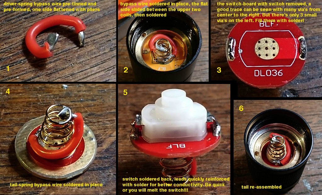
You may also want to do a spring bypass. This will reduce over all resistance in the light. Your light will produce more lumens, pull more amps and it will give your springs a longer life. Here is a proper spring bypass done with silicone insulated wire. Very flexible as to help installation and to not inhibit the spring. Courtesy of djozz. Check out some of the numbers after performing this simple mod! These are from a 5a tint. The other tints may produce higher numbers.

7-mode group for the flashlights resp. without/with wire bypasses:

moon 0.66lm/0.55lm

2 11lm/10lm

3 70lm/70lm

4 190lm/205lm

5 395lm/475lm

6 750lm/920lm

7 1240lm/1495lm at start

7 1215lm/1410lm after 30 seconds

Update 9/23/15: It’s been discussed that performing a “through pcb bypass” is a safer alternative as with the other method there is a chance your wire could eventually come loose and cause a short. Also note that you will need to pick the correct side of the switch to join your wire to. Courtesy of DB Custom

  • Best case scenario for a direct short: It happens on the negative side, your battery gets pretty drained and your light has low voltage protection.
  • Worst case scenario for a direct short: It’s on the positive side, your battery gets super hot, starts smoking and God only knows….

Here is the head with star re-installed and the centering ring put on. As far as I can tell this ring helps hold the star against the shelf. Important! Be very careful at this point some people have accidentally de-domed their flashlight putting the reflector and bezel back on. The effect is not always bad - some people do it on purpose but normally on thower lights .

If you want to get rid of the “wings” on your pocket clip the metal is generally pretty brittle. You can simply try to squeeze them flat with pliers or bench vise and most likely they will snap at a good location. After snapping the wings off I took it to my bench grinder to round off the corners then a file and finally some sand paper.

Thanks for looking! :slight_smile:

Some more repair help in order as found in thread:

  • Hank: Stuck head/ stuck retaining ring fix.

Try a drop of penetrating oil (“nano-oil” works well for me — ‘oogle it for more, it’s debated among watchmakers, gunsmiths, and other users of moving parts)

and/or a drop of tuner cleaner/electronics cleaner/lubricant (I have an aerosol can from somewhere)

Don’t pour the oil in and don’t spray the lube in directly.

Just take a drop, smallest possible amount, put it in on the end of a toothpick, and draw the tip all the way around the circle wetting it where it can work its way into the threads.

Then put it so gravity works for you and leave it overnight.

Wipe out the threads with something that won’t leave more stuff in the threads where they’re rough — microfiber cloth maybe.

Look hard for any little ‘boulders’ of swarf sitting and jamming the thread where the ring needs to turn.

Wiggle the ring gently with the needlenose pliers.

Wipe and maybe oil/lube one more drop, no more.

Why all this? Guessing/speculating these were assembled without being cleaned and/or in a dirty environment, so it’s possible any sort of stuff is down in the threads in small sized bits.

Anything from metal filings to, well, anything. So you may be trying to dissolve something, or dislodge something.

This is basically how I got the stuck head off my light.

  • ToyKeeper: More about retaining rings.

If the driver retaining ring turns a little then stops, don’t force it. Instead, turn it to the middle of its loose range, grab it with tweezers, and turn while lifting up. It may need a bit of help to “catch” the next set of threads.

On some units (including the EE ones), it seems there is a small gap between two sets of threads there. It can be tightened easily since it falls from one set to the other, but unscrewing it requires a more delicate touch.

  • ToyKeeper: TK's collection of info throughout the G.B. Check post #52 for pics and more in depth info.

Mode regulation:

Group 1 7135 power FET power

Moon 0.8% 0

Low 8% 0

Med 1 43% 0

Med 2 100% 2.7%

High 1 100% 22%

High 2 100% 54%

Turbo 0 100%

Group 2 7135 power FET power

Low 8% 0

Med 90% 0

High 100% 35%

Turbo 0 100%

Modes between 5 lm and 155 lm will keep the same lumen level for most of the battery’s life because those modes are regulated.

Modes above 155 lm will gradually decrease as the battery charge drops, with the effect being most noticeable at the highest modes.

Moon will also gradually decrease with voltage.

Another way to look at it:

Mode 1: … moon is always weird; gets dimmer on a low battery

Mode 2: regulated

Mode 3: regulated

Mode 4: 85% regulated

Mode 5: 36% regulated

Mode 6: 20% regulated, mostly direct-drive

Mode 7: 100% direct-drive, drops with voltage

The semi-regulated modes will still drop with voltage, but the slope of that curve will be less steep than if it were direct-drive.

Mode group 1:
1: 0.45 lm / 2.66 mA / 39 days
2: 10.1 lm / 11.87 mA / 8.7 days
3: 64.5 lm / 139 mA / 18 hours
4: 187 lm / 385 mA ? / 6.5 hours
5: 417 lm / 1.48 A ? / 100 minutes
6: 798 lm / 2.96 A ? / 50 minutes
7: 1386 lm / 5.65 A ? / 26 minutes
Mode group 2:
1: 9.72 lm / 11.87 mA / 8.7 days
2: 139 lm / ? / ?
3: 578 lm / ? / ?
4: 1386 lm / 5.65 A ? / 26 minutes

Mode spacing:

This is fixed in the BLF A6 and in the BLF X6v2. The approximate output levels of those are (so far):

  • 0.35 lm (visually 0.70)
  • 11.8 lm (visually 2.28)
  • 65.9 lm (visually 4.04)
  • 190 lm (visually 5.75)
  • 427 lm (visually 7.47)
  • 832 lm (visually 9.41)
  • 1494 lm (visually 11.43)

The “visual step” gaps here are: 1.58, 1.76, 1.71, 1.72, 1.94, 2.02. Those last two are a bit brighter since it was calibrated without spring bypasses, and this sample had a spring bypassed. In stock form, each level is about 1.7 “perceptual units” away from its neighbors. And the brightest mode looks about 16 times as bright as the lowest mode (though in reality, it’s ~4200 times as bright).

Or in the 4-mode group…

  • 11.8 lm (visually 2.28)
  • 143 lm (visually 5.23)
  • 588 lm (visually 8.38)
  • 1494 lm (visually 11.43)

These gaps are: 2.95, 3.15, 3.05.

Hi, just a quick update with lumen measurements from a totally stock production unit in 3D tint. I used a Samsung 25R cell charged to 4.18V, and measured the initial output (not at 30 seconds).

Lumens at each mode, group A:

  • A1 : 0.55 lm (visually 0.82)
  • A2 : 11.79 lm (visually 2.28)
  • A3 : 71.03 lm (visually 4.14)
  • A4 : 197.6 lm (visually 5.82)
  • A5 : 450.0 lm (visually 7.66)
  • A6 : 874.1 lm (visually 9.56)
  • A7 : 1351 lm (visually 11.06)

Lumens at each mode, group B:

  • B1 : 11.81 lm (visually 2.28)
  • B2 : 147.4 lm (visually 5.28)
  • B3 : 613.8 lm (visually 8.50)
  • B4 : 1351 lm (visually 11.06)

The “visual” units are a cube root of the lumen output, based on the “visually linear” scale used by selfbuilt. They represent how bright it looks to the eye, in arbitrary units.

Perceptual mode spacing: (visual increase per level)

  • Group A: 1.46, 1.86, 1.68, 1.84, 1.90, 1.50
  • Group B: 3.00, 3.22, 2.56

The levels could be a little more evenly-spaced, but it’s not bad. I calibrated the sample to 1.70 perceptual units between each group A level, and IIRC about 3.00 units for each group B level. But it’s close enough that it looks pretty even in person. And I expect it will vary per-unit anyway, so the spacing should be pretty close overall. Also, the space between upper levels will increase with a spring bypass.

  • Some useful battery info from ToyKeeper:


FWIW, I usually try to keep my cells somewhere in the middle of their charge. Discharging too far can damage the battery, overcharging can damage the battery, and even resting unused at 100% charge for long periods can permanently reduce the capacity. I hear the recommended storage voltage is about 40%, to maximize the number of years a cell will last.

So, I generally charge a cell to 4.18V (picked a charger on purpose which stops a little early), use the light for a while until it’s down to one or two blinks, then switch to a different light and repeat the cycle. This way I get to use all my lights, and I avoid the conditions which reduce cell life.

The LVP functions should work reliably, and are intended to let you get the last few drops of power out of a battery without actually getting into dangerous territory. Draining a cell that far will use up its lifetime-in-years faster, but it won’t actuallydestroy the battery.

Quoting a guide from Texas Instruments… “Another easy way to destroy an Li-Ion battery is by discharging it too far. The Li-Ion cell should never be allowed to drop below about 2.4V, or an internal chemical reaction will occur where one of the battery electrodes can oxidize (corrode) through a process which can not be reversed by recharging. If this occurs, battery capacity will be lost (and the cell may be completely destroyed).”

A 2.8V cut-off is a balance between using as much power as possible and avoiding cell damage. There’s only like 2 or 3mAh left at that voltage, so you’re not missing much. It also provides a longer window for the operator to react and click the light completely off.

The way it behaves in testing is:

  • While the light is on high, voltage slowly drops to 2.7V.
  • LVP kicks in and drops the output to medium.
  • The battery recovers to 3.0V and runs for a while.
  • Voltage eventually drops to 2.7V again, so LVP activates and puts the light into low mode.
  • The battery recovers to 2.9V and runs for a while.
  • Voltage drops below 2.8V again, but there is no lower level to drop to. LVP shuts the light off and enters deep sleep mode.

This has mostly been tested on a bench power supply though, since I have no 3.0V cells to test with and don’t want to regularly inflict this kind of abuse on my 3.6/3.7V cells. Plus, it makes testing a lot easier and faster.

If the light was in a blinky mode when LVP hits, it’ll “step down” to medium then proceed normally. You can also bump the mode back up if desired, but it will probably step itself down again within a few seconds.

About all I have time for tonight. Will do more later! Thanks for reading! :)

I could have sworn that there was a thread devoted to the BLF A6 problems, as this one is, so as not to clutter up the main group. I believe it was started by chouster. Anybody know what happened to it?

Hi BLightSam, I didn’t start a thread on that topic, I think CircaM started one, because of the issues with he had his unit.

OP has a lot of good info. Seems like a good start to a very informative BLF A6 fix-it and mod knowledge base.

Yet another my misinformation. :zipper_mouth_face:

never mind :slight_smile:

Thanks dudunphy. Not only will it potentially address some concerns of the BLF A6, but looks like it might be a good resource for newbies like me who fear messing around with the guts of a light; kind of a flashlight basic training. Chances are the info is on BLF, but can be lost in threads with more technical info.

subscribing…

Thanks! I was hoping I could help a few people! If you do some searching there are other beginner type threads. But I was hoping to help people with this particular light as it was such a huge thread and a great seller. :slight_smile:

For the noob by the noob!? :wink: :stuck_out_tongue:

Hello added some more stuff. Run times Flashlight wiki link. More explanation on how you can check amperage with another pic of the tube.

I don’t envy you, trying to put all the useful info in one place.

But I’m glad you’re doing it! :slight_smile:

Is there any solution for pitchi sound on Hi modes, my is just too loud, even my kid standing 10 feet from me asked me what is that noise. I know kids can hear better then us hi frec. but i can hear it too. Its only when current is regulated, so 5th and 6th mode, or 3th in 4 mode configuration.
Thanks
Nikola

If it has a high-pitched whine, there is probably something wrong with the light. It should be generating sound… but it’s pulsing at 19 kHz which should be too high for almost anyone to hear. However, if the driver is under-clocked or there’s a weird connection making resonance, it could be making different frequencies.

If you put the light in bike flasher mode, it should stutter once per second. But if the driver is under-clocked, it would then stutter slower, like once every 2 seconds or 4 seconds. I’d suggest testing this first before opening the light to look for anything else which might be weird.

Yes its stutter once per second, maybe it just bad solder like from the picture above, I will try to reflow. Also might be that all one have this but no one have noticed. Just put the light closer to the ear and check it out ?

I’ve heard that too but not every time. I’m gonna put a fresh cell in the one I went through and see because I felt like it was when pushing high amps.

Haha thanks TK please if there is any thing you want on here let me know. I still really don’t understand the in and out of why this resistor here and this size resistor there. You and wight (who am I missing. db?) seem like the pros!

I definitely am getting a squeal in modes 5 and 6 on both of my lights.

So it just so happens today that I am working on a sound proof booth here at CSU. Lucky me the doctor in charge of this is studying how auditory signals affect brain waves. :slight_smile: We got to talking about khz so I brought up the 19 khz TK had mentioned. He said that while most people cannot hear that pitch - some nice sound systems are designed to reproduce up to 20k just in case I can’t remember the number he threw out but some people can get up there with good ears. Also he explained that like trying to talk under water you can hear but the water really puts a damper on the frequencies.

So what I got out of it is the metal or something around the driver is being resonated at a pitch we can hear. My thought is something is echoing the 19k at a slower rate like the capacitor or a mixture of things bouncing little sine waves around at a different rate?

One more thing I have noticed and mentioned before,is that head is not waterproof,glass is sitting directly on metal,and no O-ring between. . . so dont put it in the watter couse led is almost directly exposed

Well with a thread like this started, you may also be be one of the pro’s shortly!

Seriously good thread here, should be stickied….