The Nut Light seems an ideal host for a compact inexpensive zoomy with a 6 volt multi die LED. The 3 x AA holder should be able to hold 3 x IMR 14500, which should be able to supply at least 3 amperes at between 10.8 and 12.6 volts. It has a large pill with space for a buck driver that should be able to convert that to well over 3 A. at well over 6 V. It comes with a long focal length (thin) 50 mm. lens that can give excellent throw, and a somewhat shorter focal length lens is available from DX in case a larger spot and more total output in throw mode is desired. The resistance in the parts of this cheap host will make less difference at the higher voltage. I have an aluminum 3 x AA carrier that fits and has lower resistance. That should work, but at this point it seems harder than it sounds.
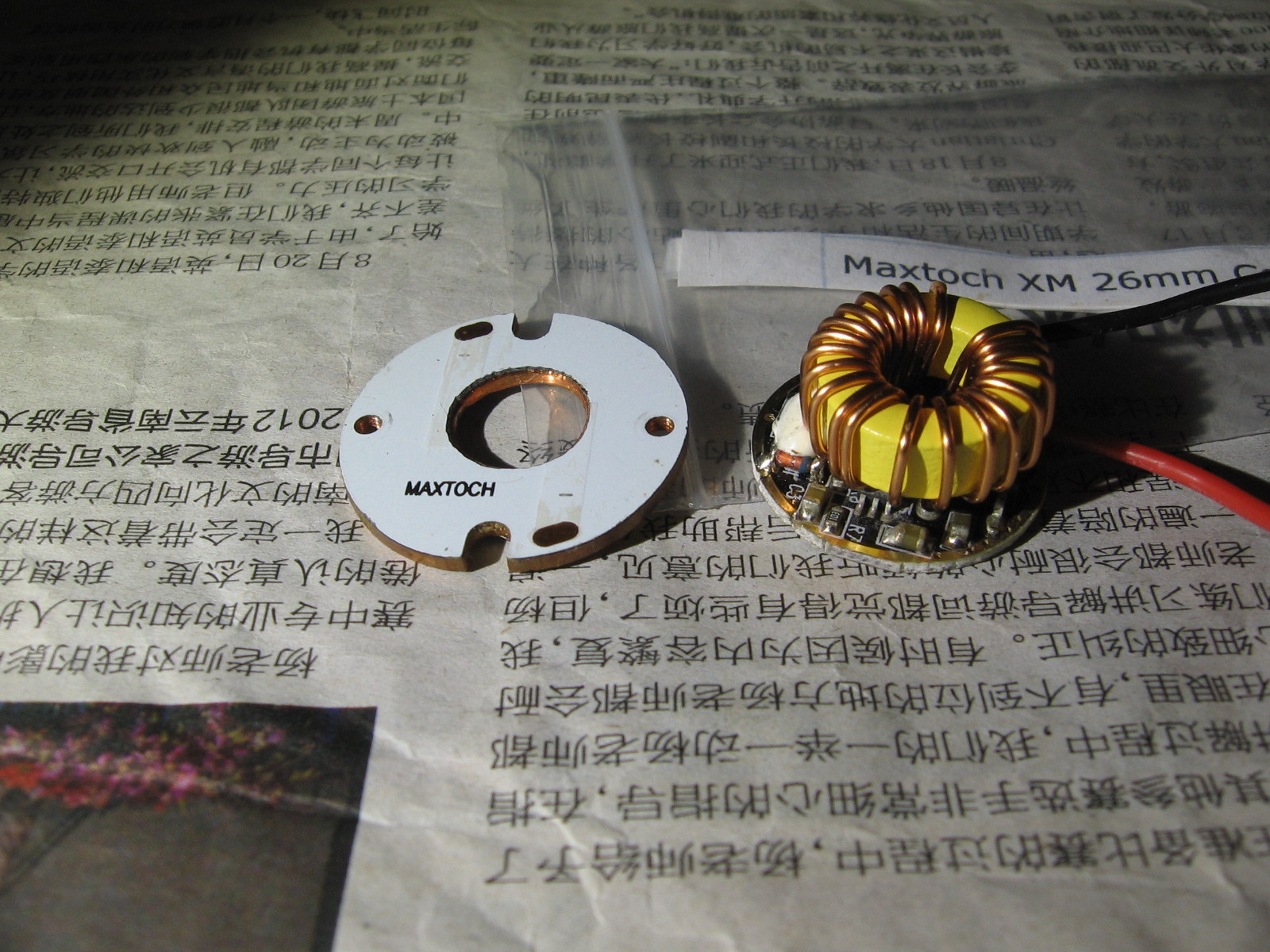
I ordered another Nut Light, an XHP-50, an IOS LD-2D buck driver for 6 V. LED and two Maxtoch XM 26mm Copper MCPCBs.
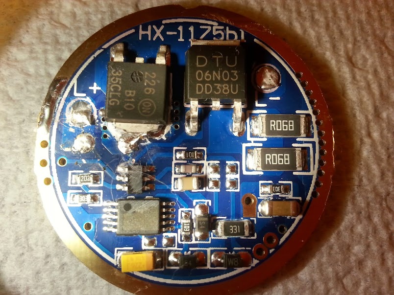
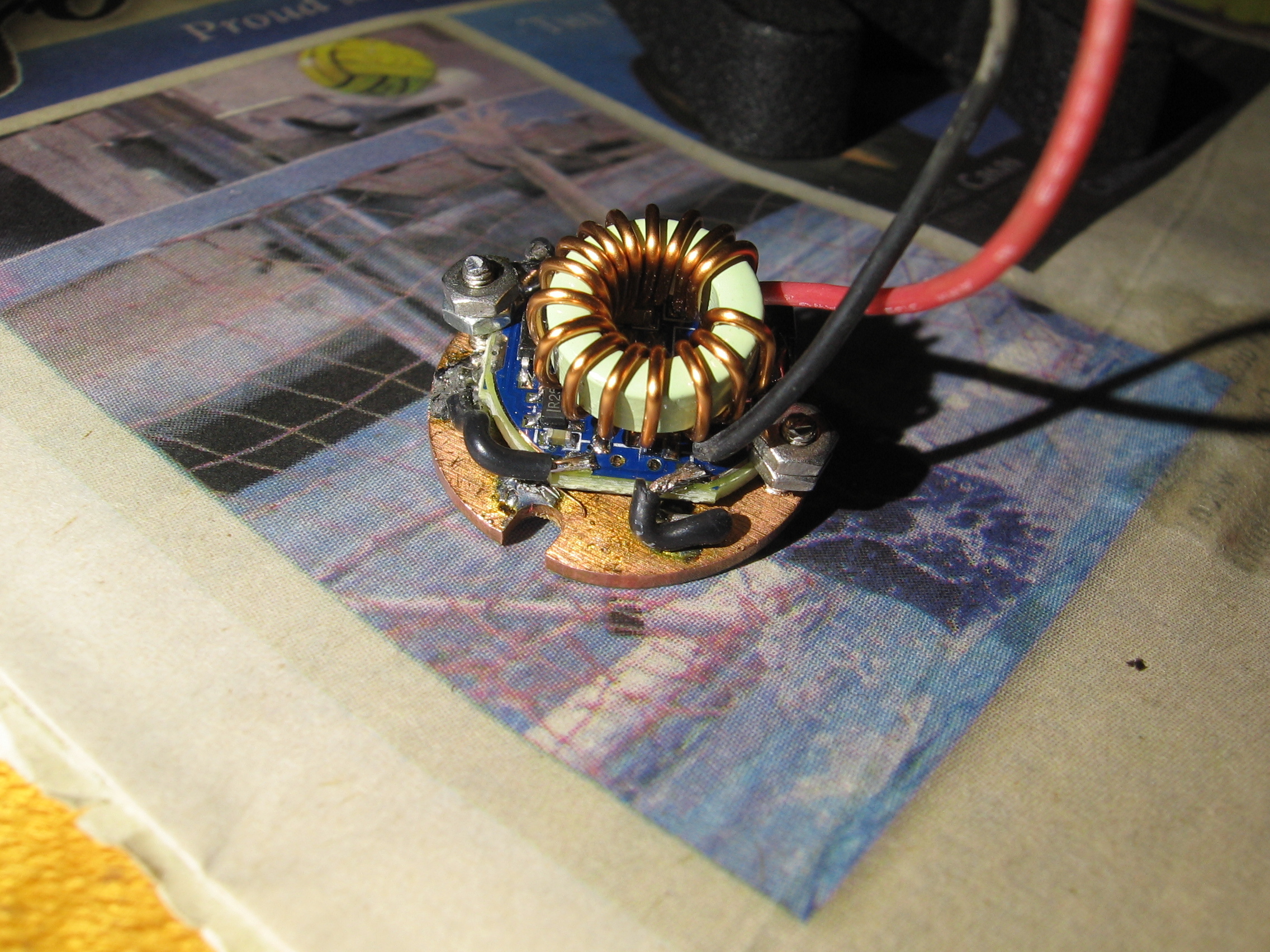
IOS driver
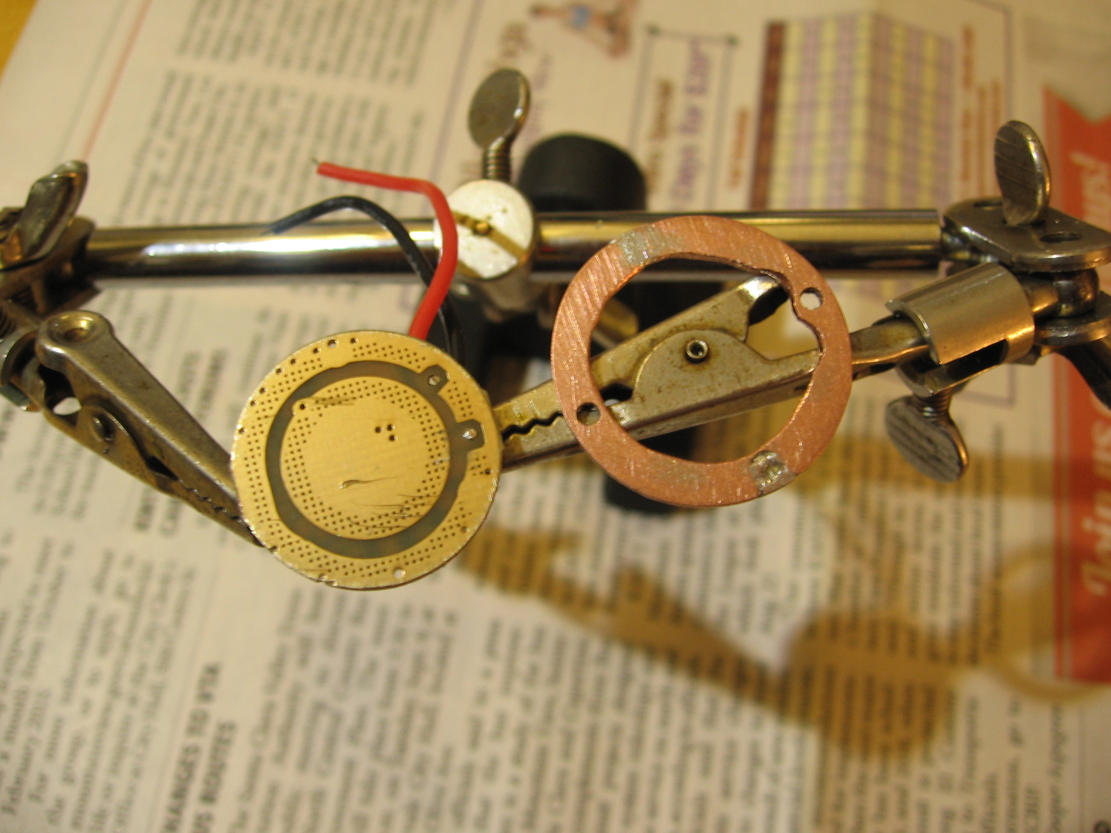
With more experience, I might have found a 27 or at least 26 mm. driver or and adapter plate, but I bored a hole in one of the Maxtochs and attached and connected it to the driver.
Click for full size. 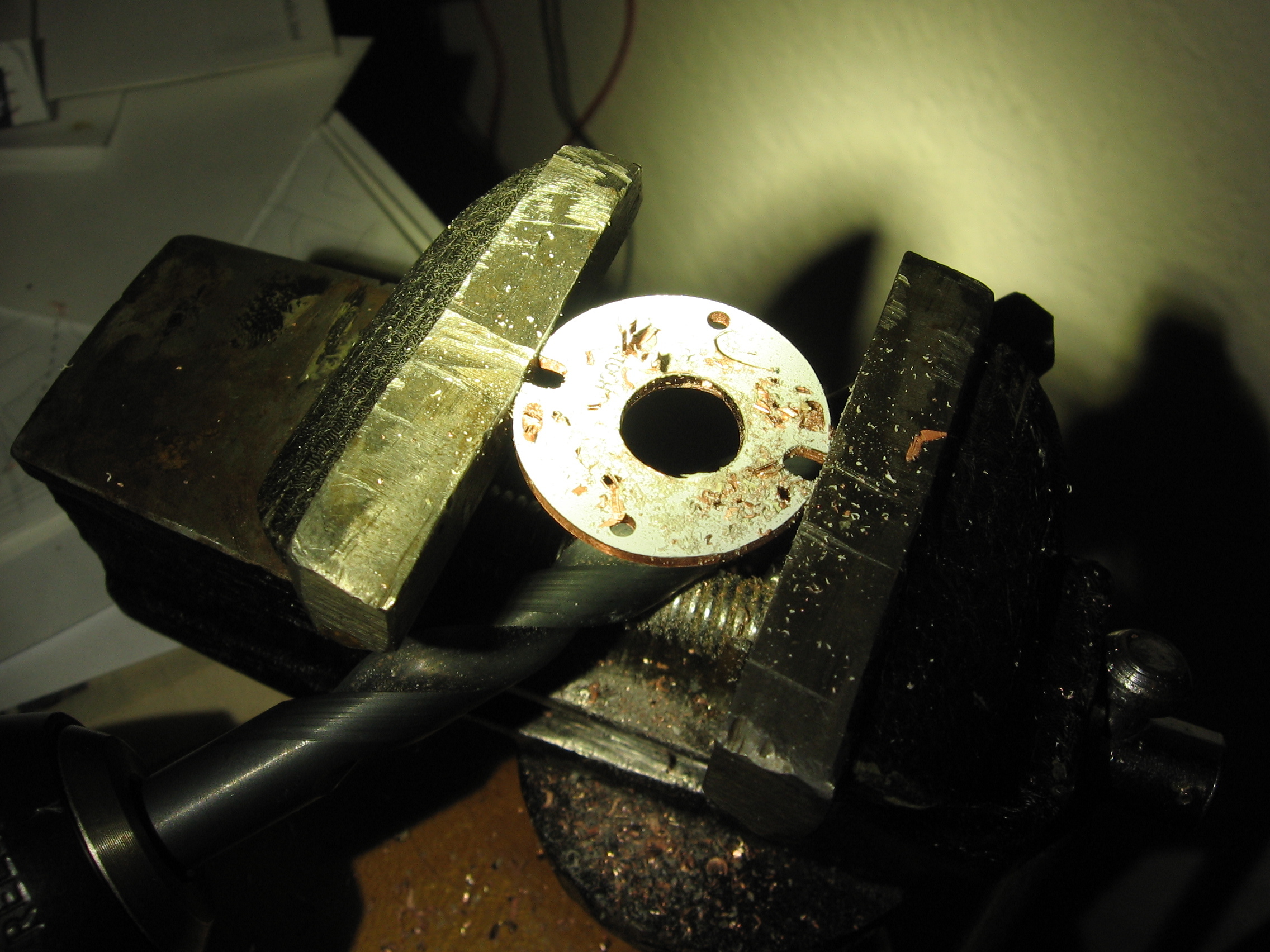
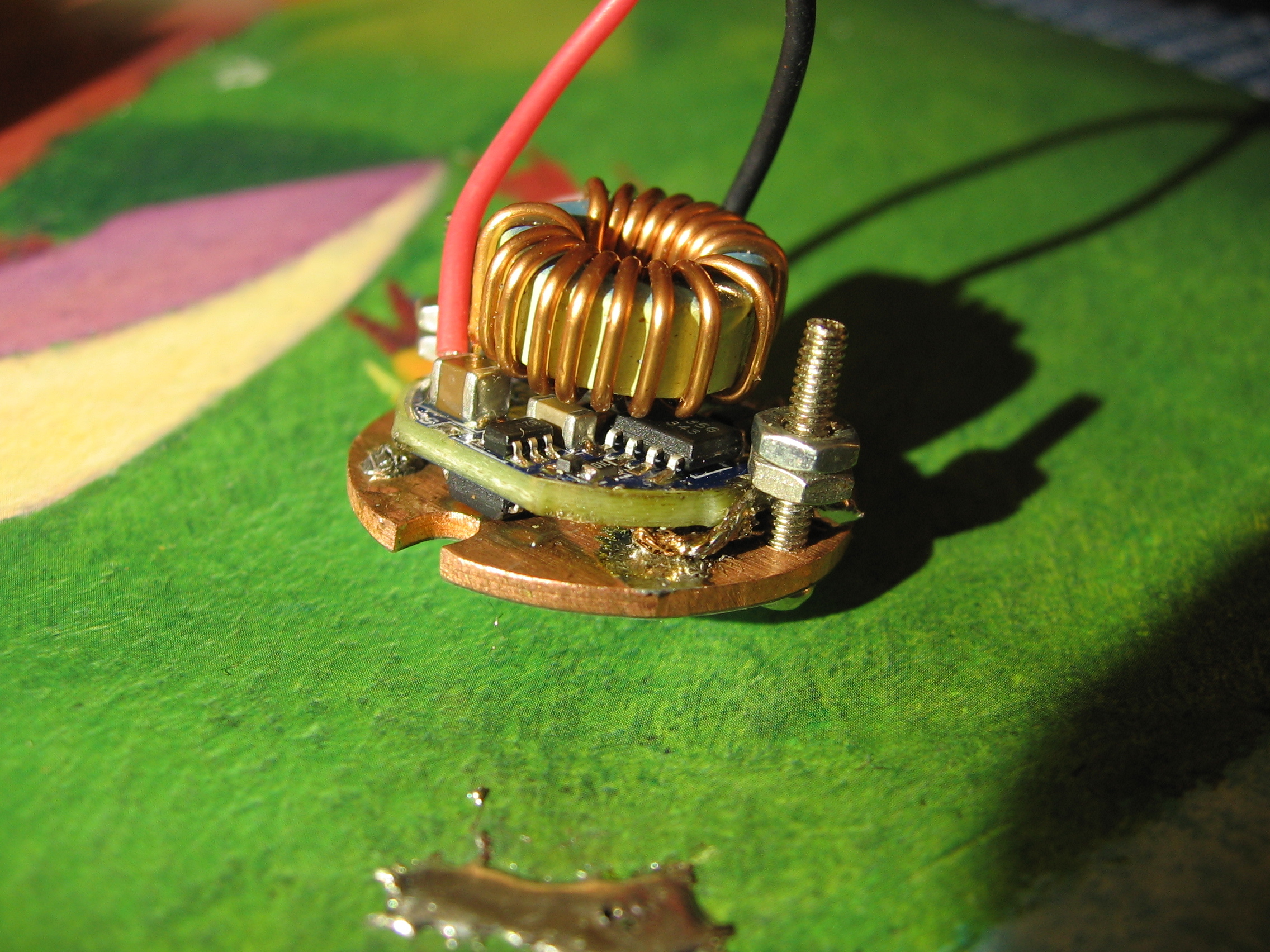
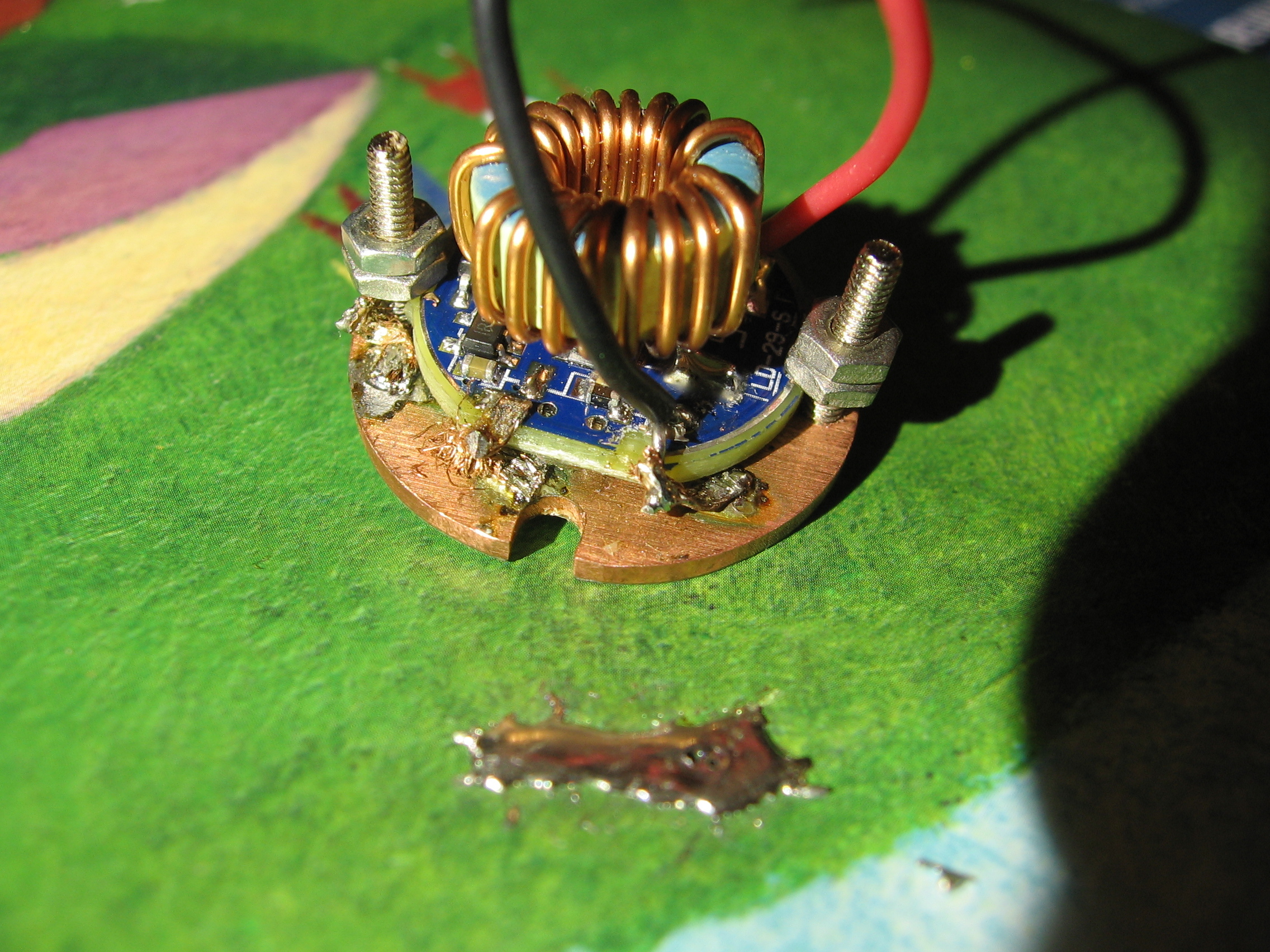
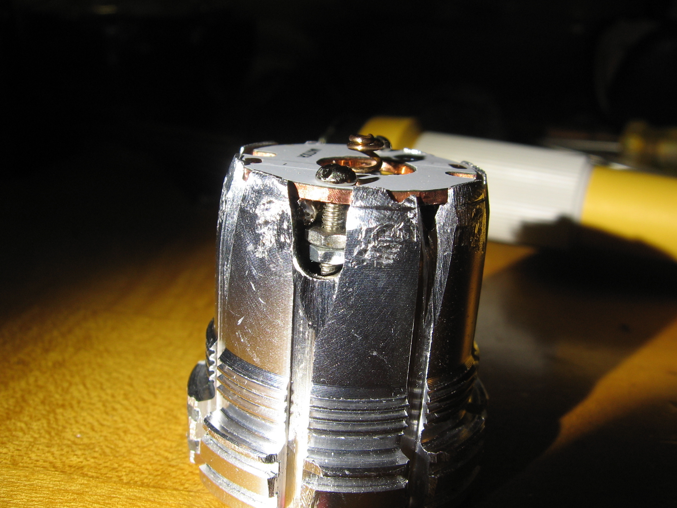
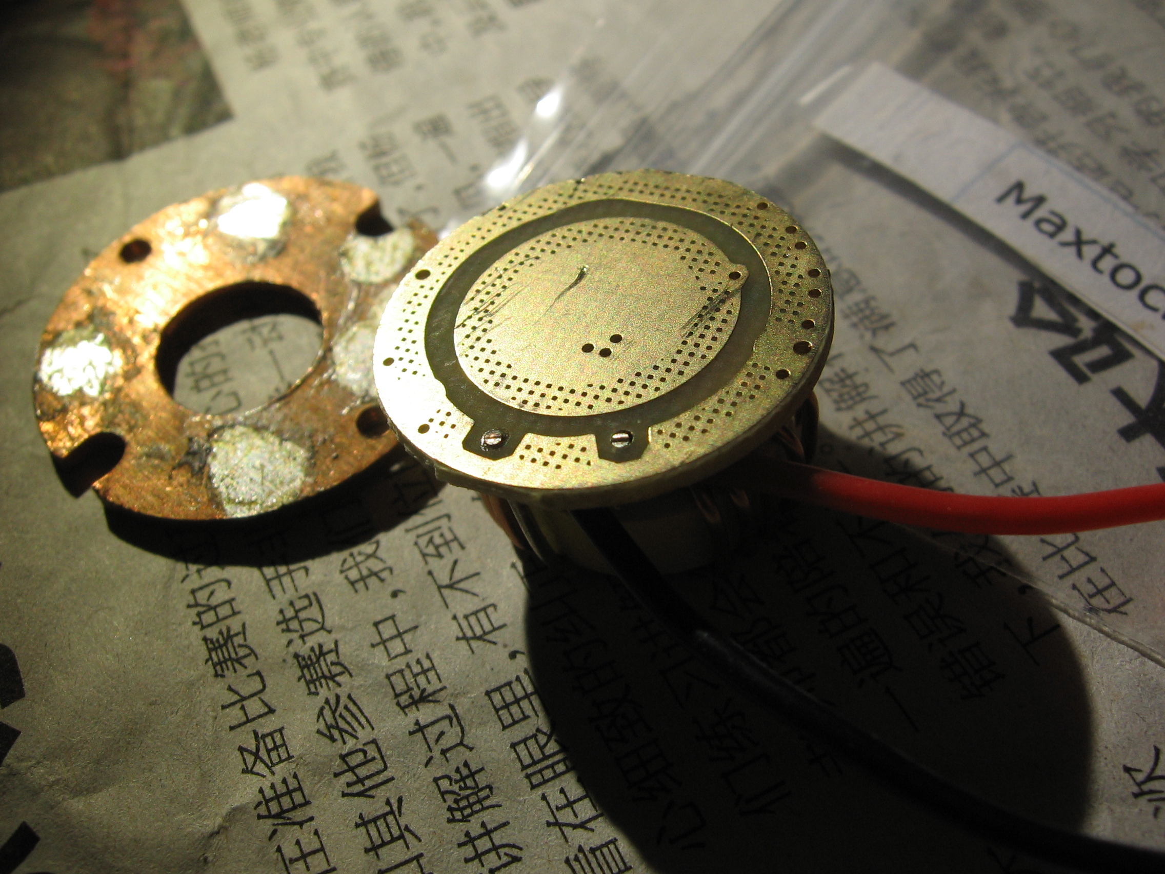
Since the driver supports the contact spring, I attached it with two bolts from my old collection of Cox 0.049 cubic inch (0.8 cc) model airplane engine parts.
My first attempt to make electrical and thermal contact only destroyed the driver.
I used a bronze spring trimmed to size to avoid the necessity of braiding.
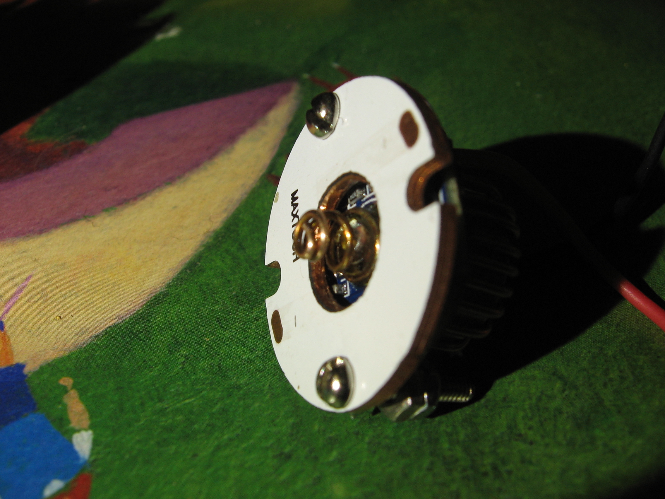
The star was a bit smaller than the original driver, so I slotted the pill so I could compress it to fit. I filed two slots wider to make room for the bolts and nuts.
On the second attempt, I got the driver connected and working, using 24 gauge silicone insulated wire. I soldered to the plate before soldering to the driver, to keep the wire from coming loose from the driver when I was soldering to the much more massive plate. In one case, I soldered one wire to each and then the two wires together.
-
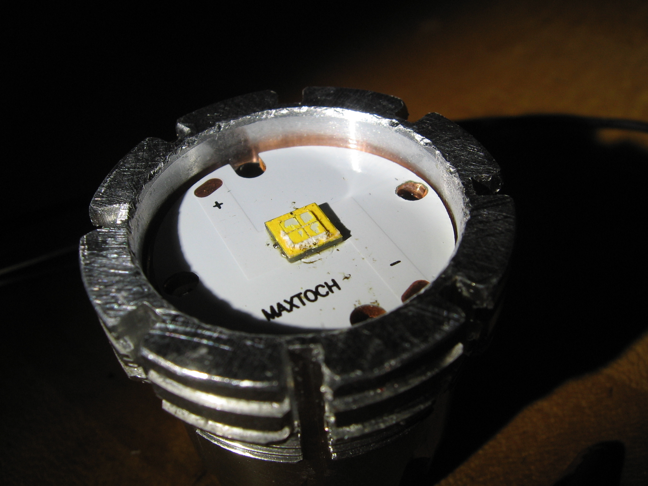
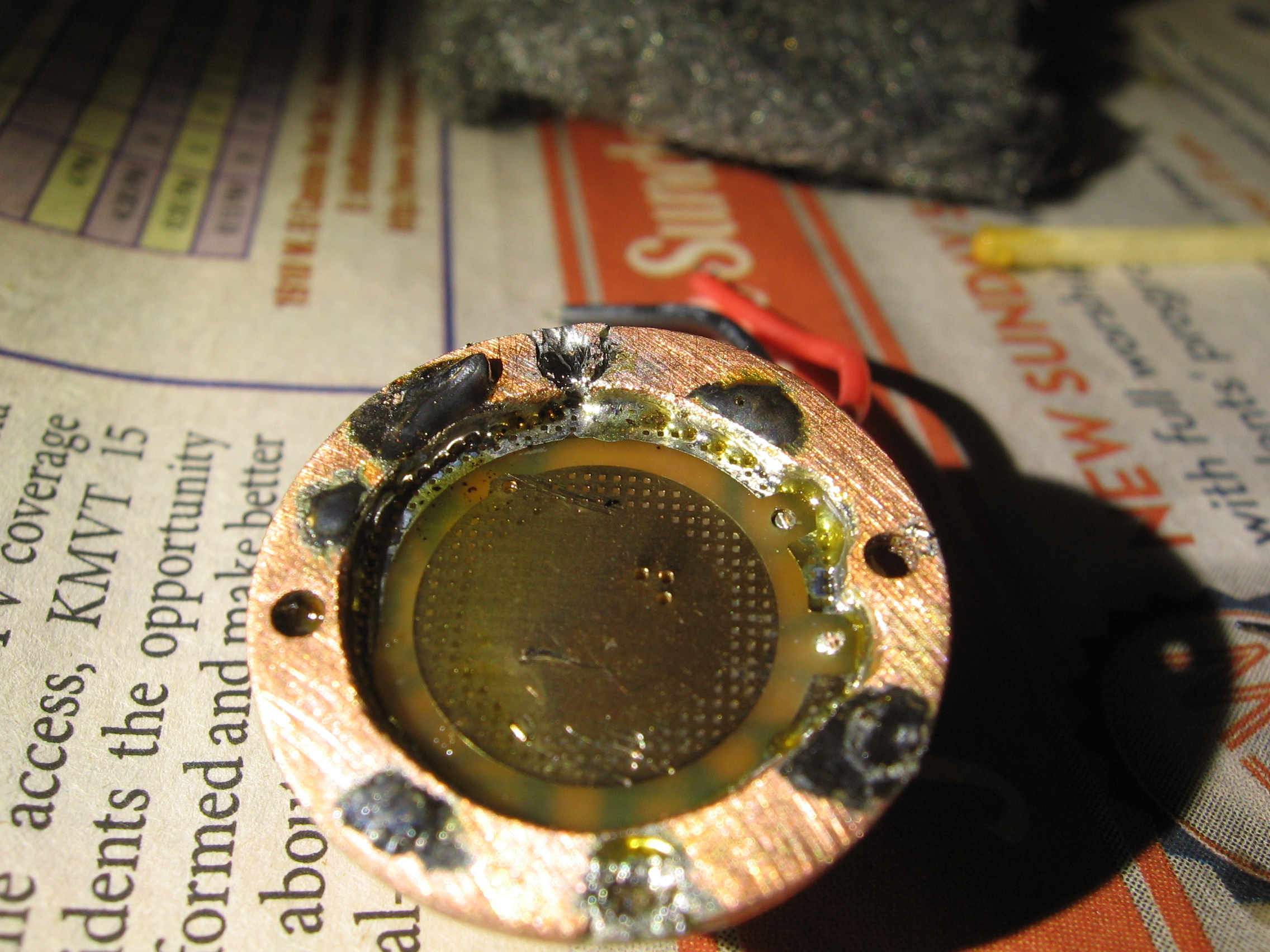
Since I had ordered the XHP-50 before planning how it would be used, I had to re-flow it onto the other Maxtoch. It slipped out of the tweezers, popping the dome off.
Not having the right washers, I used the old plastic ring to hold the star in the pill.
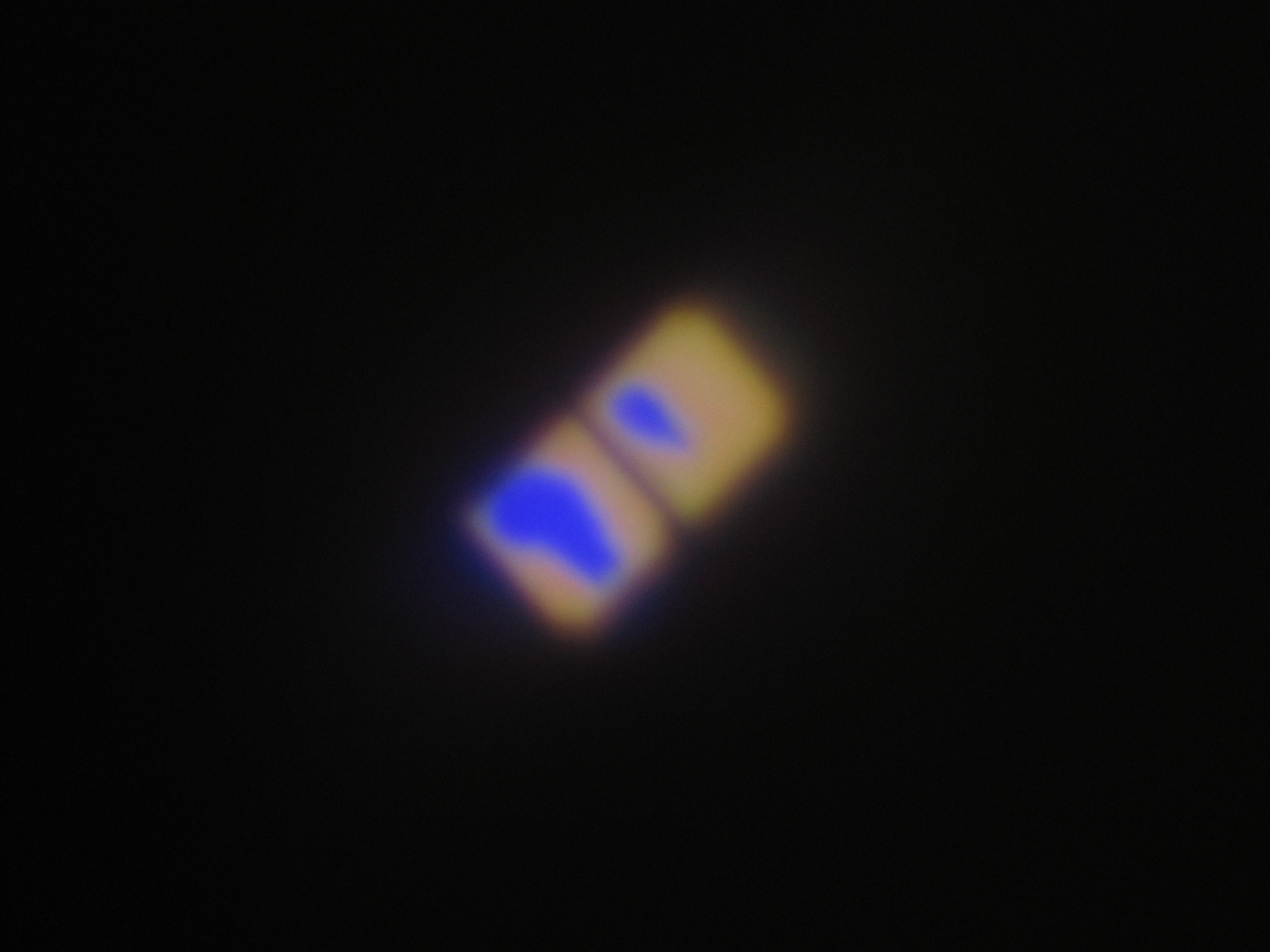
When I got it all together, I found it only worked in low mode, though it switched modes when I tested the pill outside the host with two cells.
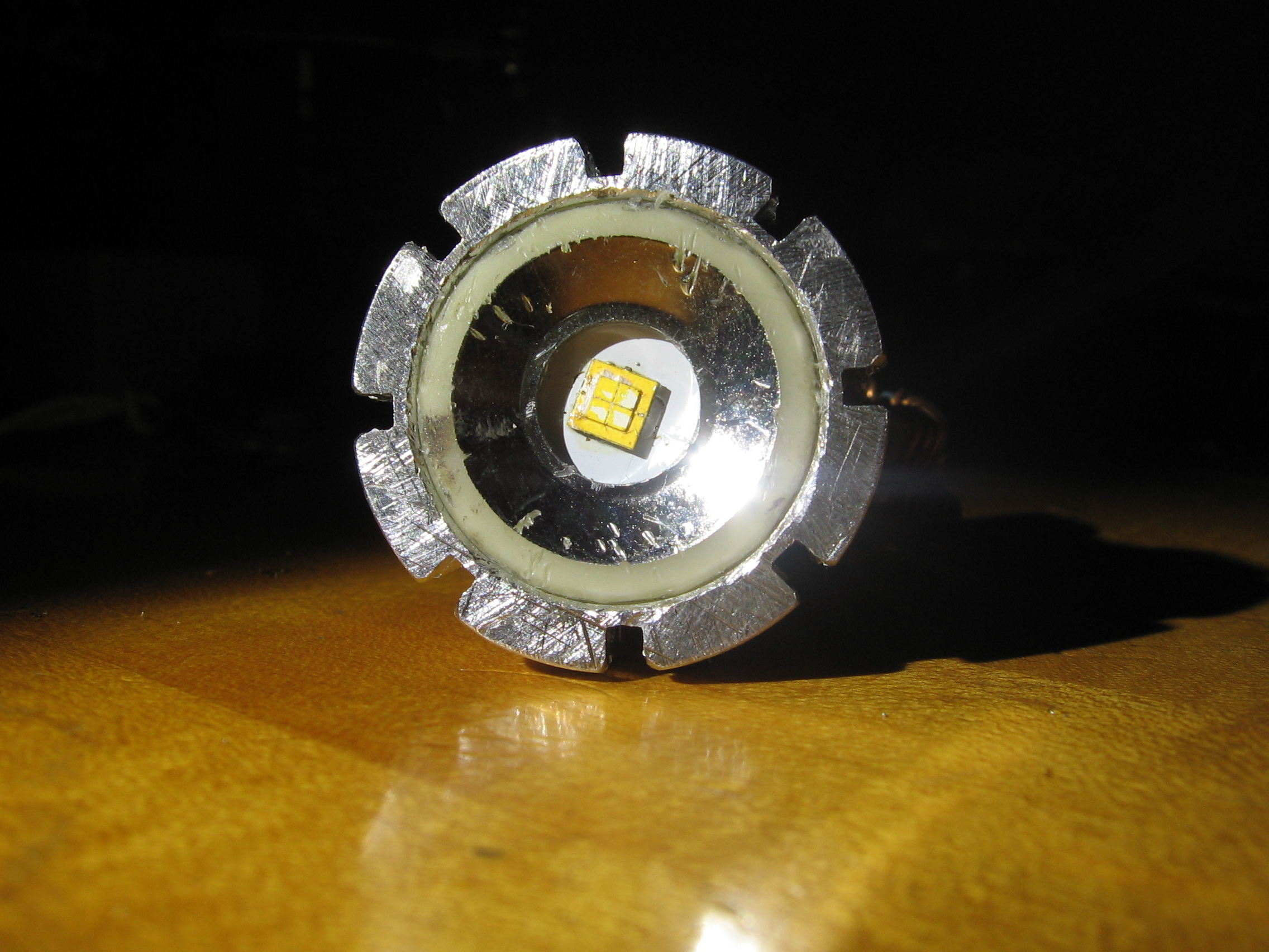
When I got the lens on, it became obvious that some bond wires and phosphor came off with the dome.
Even my button top 14500s didn’t fit the holder that came with it without some fiddling. The protected cells are too long and the buttons are too short.
The aluminum 3 x AA carrier fits the IMR cells, both button and flat top, though protected cells are tight. I see one like it at DX but can’t find my order for it.
The second IOS LD-2D driver worked intermittently for a while and then quit. With three cells, in the flashlight, it wouldn’t switch modes and soon stopped working entirely . The description says “*Suitable for 2-3*18650, 26650 or 16340 batteries.” Clearly 14500 IMRs are equivalent. Perhaps the cooling was inadequate, because it was connected to the ground plate only at a few points. That doesn’t seem to explain not switching modes, though, because the driver must take time to heat up.
Dimensions
The space for the star is 27 mm. The driver is about 28 mm., but I have my pill crimped to hold a 26 mm. driver.
-
DX driver
It is this one: http://www.dx.com/p/t6-2500-3000ma-3-mode-regulated-led-driver-circuit-board-for-diy-flashlight-4-5-18v-128269#.VgeGtysy1uY.
I am making an adapter plate out of the Maxtoch, but the DX driver is crowded.
It doesn’t really have any component free area to press against the adapter plate. It would make electrical connection with pressure, but attempting to solder its top to the plate might unsolder some components.
It is (almost) one sided, so I could solder the ground ring to the plate. That might not be mechanically strong, as the copper could delaminate under spring pressure.
I soldered the ground ring to the adapter ring.
It is solidly soldered so the whole ground pad would have to delaminate at once to break under spring pressure.
It has worked for longer than the IOS driver did.
I might have preferred that it burn out the remaining pair of dice of the XHP50, but it is encouraging to have a working though lame flashlight. I have a new XHP50 on order from Richard. It is almost time to order a matched set of cells for it.
It draws 2.1 A (through a cheap multi-meter) from three IMR cells charged to a total of 12.0 V.
This driver has a serious problem (for those of us who don’t change the firmware): next mode memory. Ok for testing, but no one would want to use it.
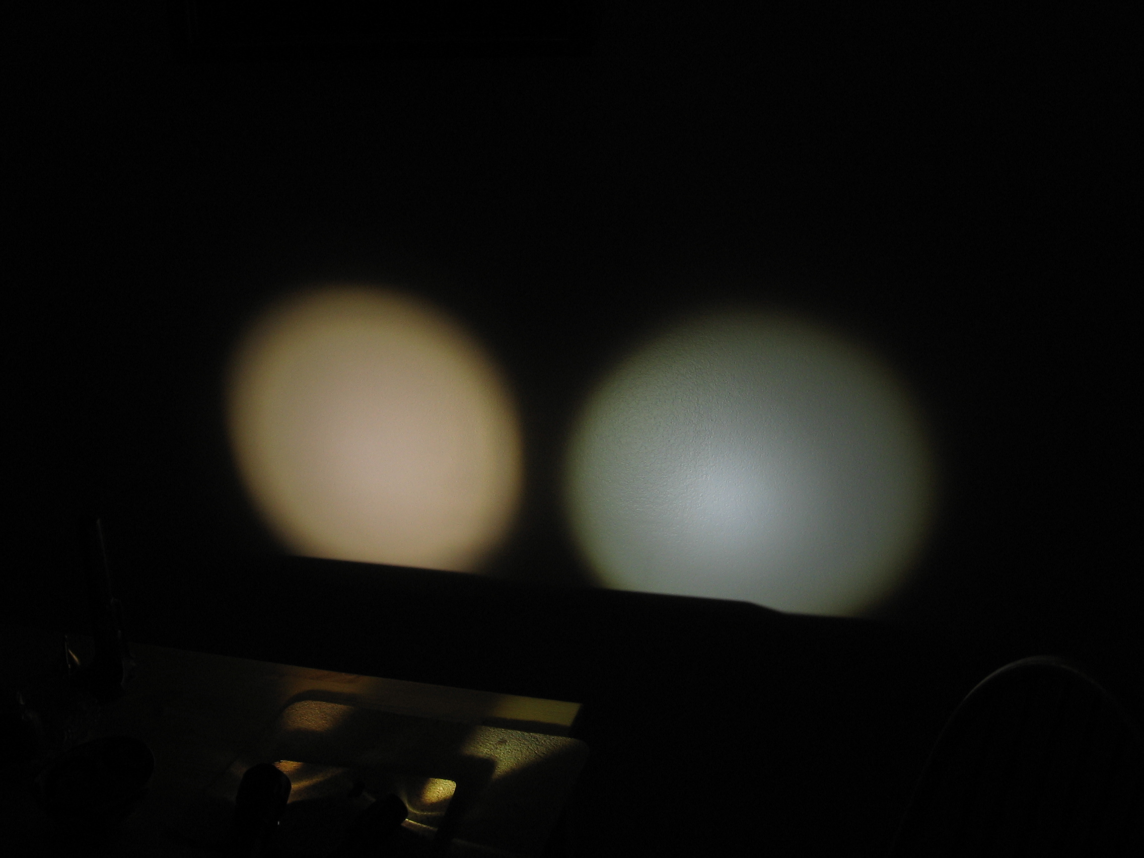
Comparison to mildly modified TrustFire Z5 https://budgetlightforum.com/t/-/34851:
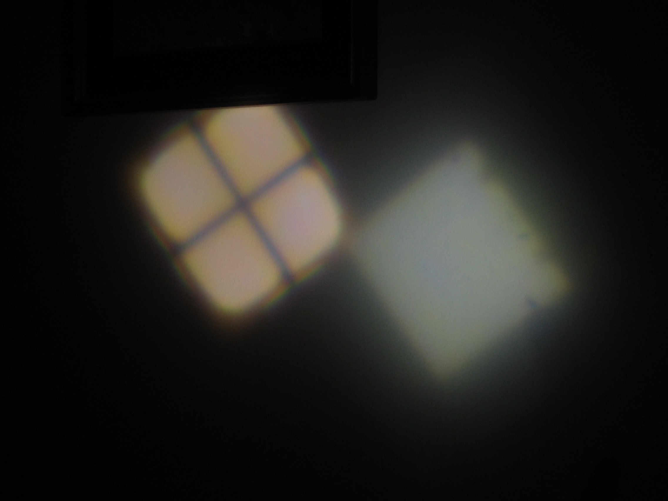
Zoomed in
This is with the original long focal length lens in the Nut and a shorter focal length DX lens in the Z5.
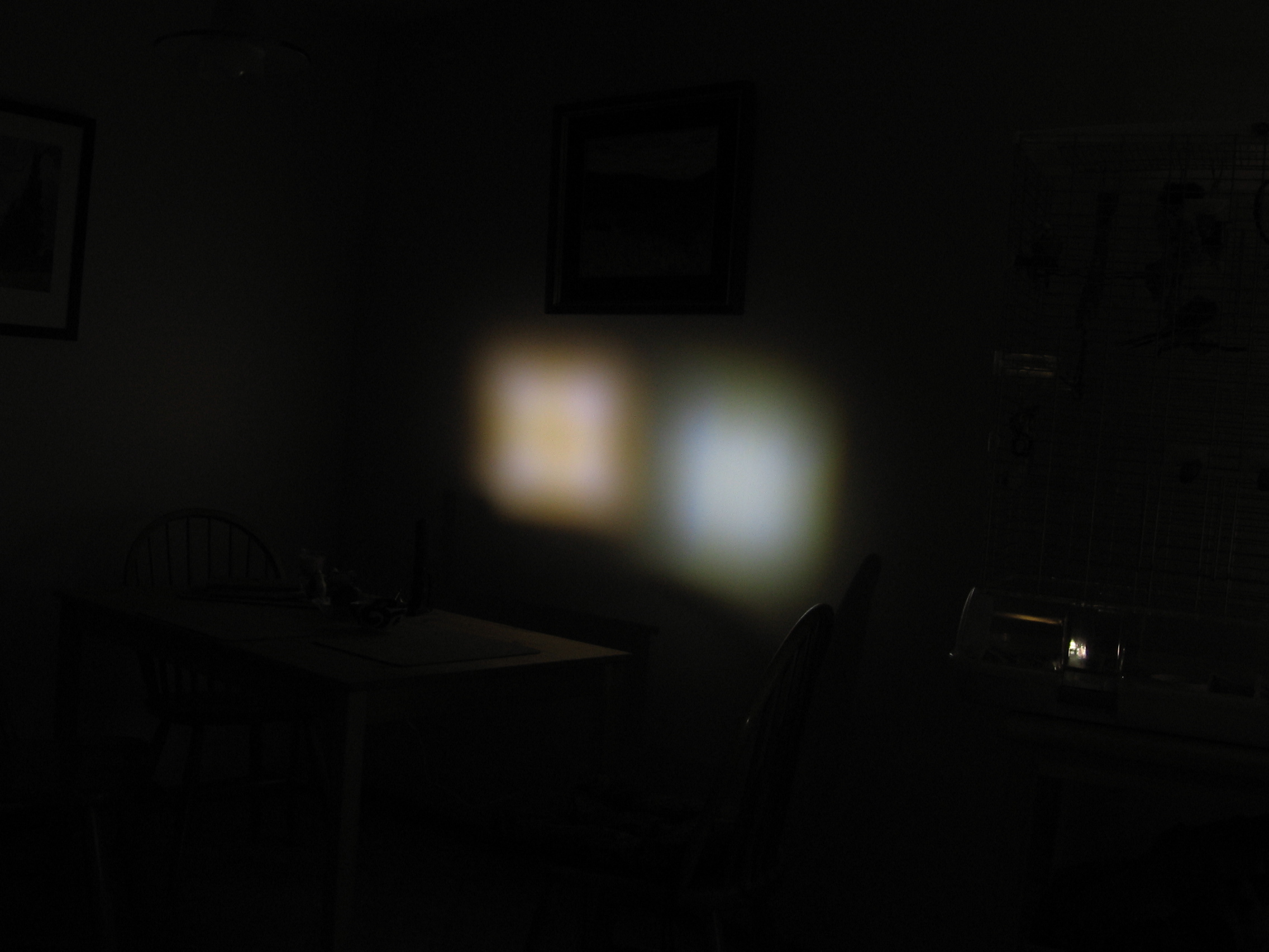
Both full flood and Z5 closer to wall
The Nut gets noticeably warmer, so I have hopes for it with a new XHP50.
The threads on the two ends of the battery tube don’t match, so there isn’t an easy way to make it 6 x AA. It could probably be re-threaded to fit.
The DX lens has a millimeter thicker flange and bulges out more than the stock one. The bezel ring holds it on but does not screw down all the way. Filing half a mm. off the face, beveling the inner edge a bit and putting the flat gasket in front of the lens rather than behind allows the bezel ring to screw all the way one.
Run time is less than ten minutes, limited by an AW cell that I have been using in all my highest powered 14500 lights. When it is really working, I will get a matched set. It looks like they will have to be IMRs.
It gets very warm. The part of the battery tube nearest the head gets the hottest.
New XHP50
My neighbor kindly brought over the XHP50 J2 5a that the postman had misdelivered.
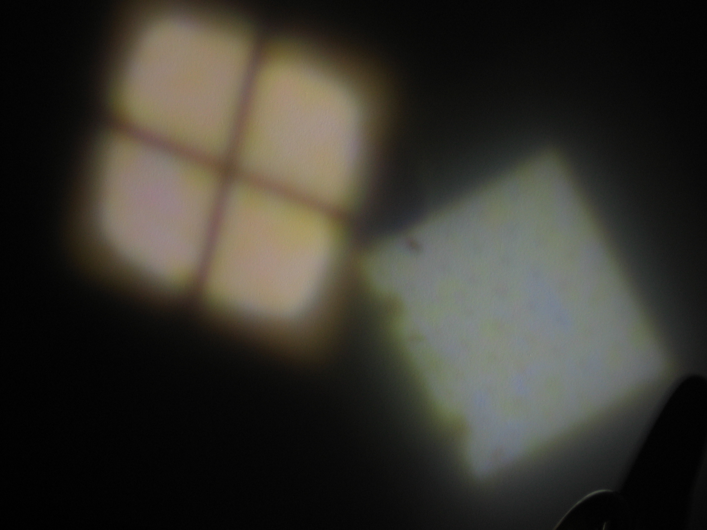
Focused,
Defocused to reduce dark lines,
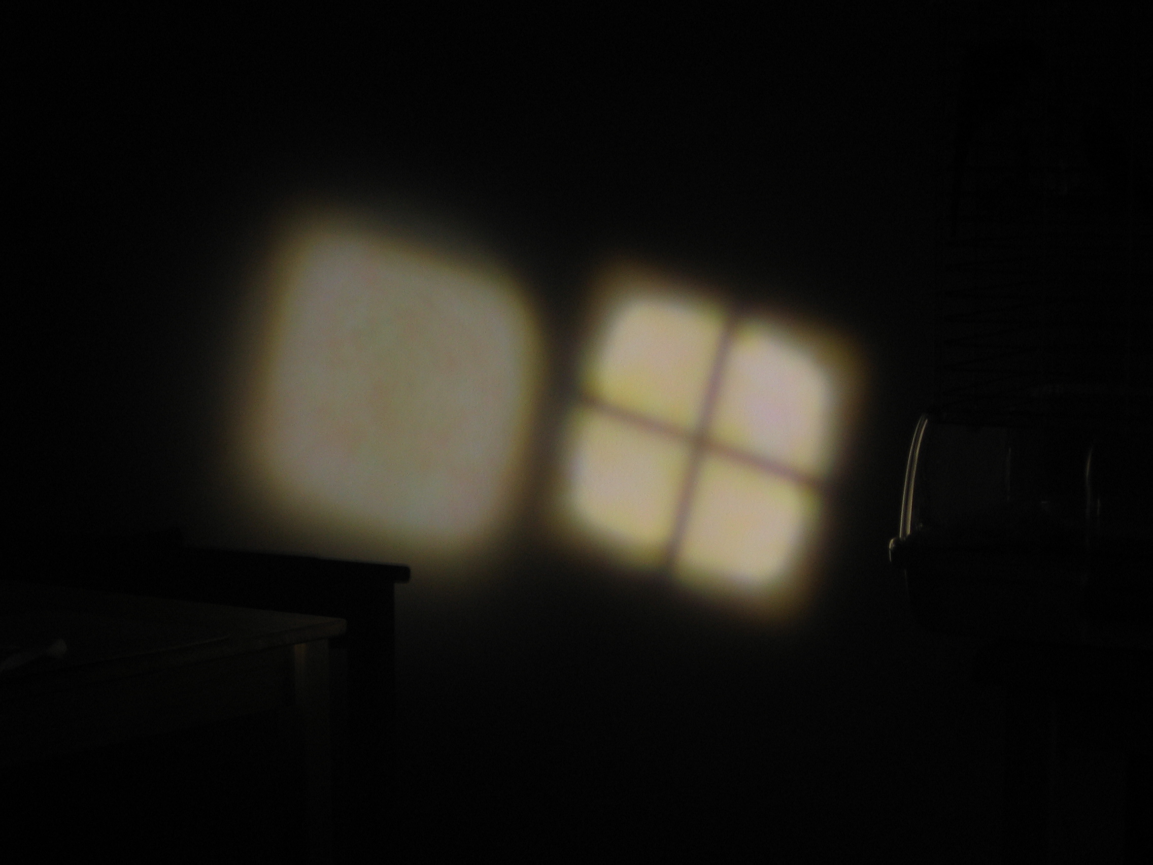
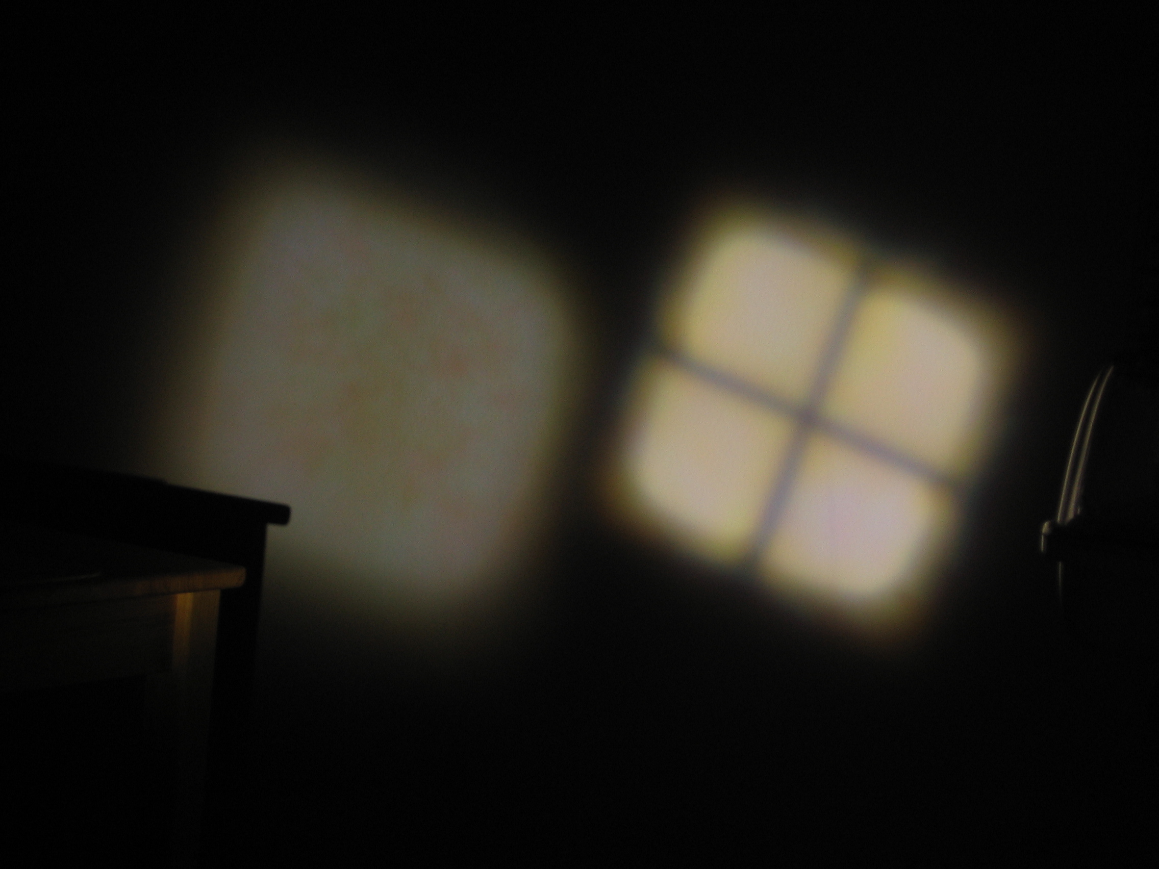
Flood flood to similar size,
And with the shorter focal length DX lens
The wall is a bit pinkish, in case this doesn’t look like 5a.
Not knowing which capacitor was responsible for the next mode memory, I penciled them all. It starts in high now.
The three cells measured 12.5 V at the start and 11.5 at the end.
At 11.5 V it is drawing 1.94 A in high and 0.4 in low mode.
Unloaded battery voltage and flashlight current:
12.7 V 1.73 A
11.5 V 1.94
10.9 V 1.92
10.6 V 1.97
It appears that there is regulation, because the input resistance is sometimes negative.
It is brighter than any of my other lights, though I would rather that it were driven harder. Run time will be around 15 minutes, but I don’t actually have a practical use for it, so that is fine. I may eventually try the KD driver that I have. The main advantages of this mod. are low cost and small size, relative to other XHP50 possibilities. It maintains brightness well as battery voltage decreases. The disadvantage of this configuration is that 14500 cells have less capacity relative to their size than 18650 cells do. The only thing that is particularly difficult about this mod. is getting the driver to fit the pill.
-
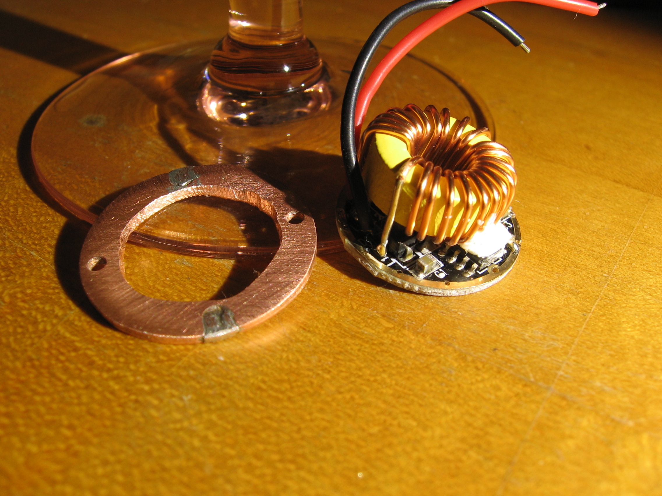
Kaidomain driver
I have this driver from Kaidomain:

The components look hefty and it is 26 mm. in diameter. The inductor coil is big though a bit smaller than that of the DX, and it looks to me like a big FET and doubled up free wheeling diodes.
I don’t have a supply of 6V LEDs and my one is built into this light. But I had a damaged XHP-50 that still worked to some extent.
Currents:
2 x 18650 in: 1.4 A, out: 1.3 A
3 x 18650 in: not measured, out: 3.7 A
It took me too long to measure the 3 x output and the LED, with only the Maxtoch star for heat sink, suffered further damage. The measured LED voltage at 1.3 A was 6.8 V.
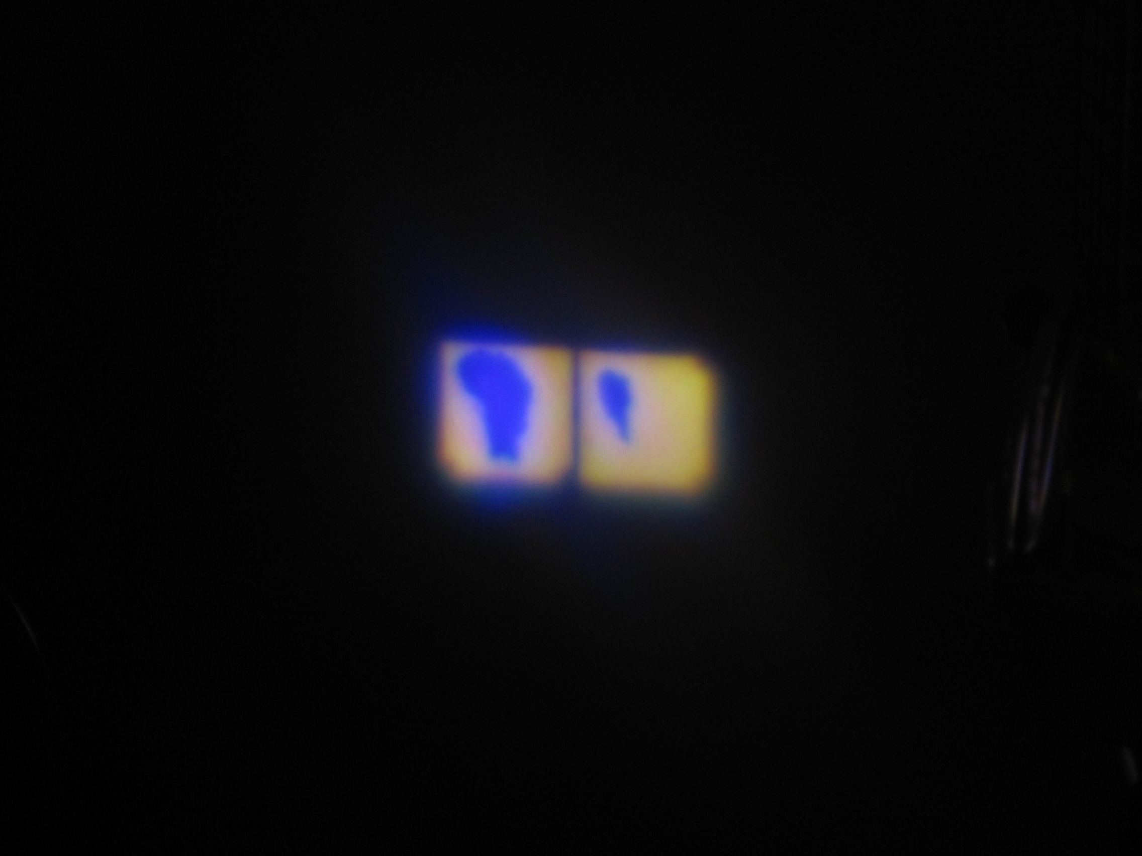
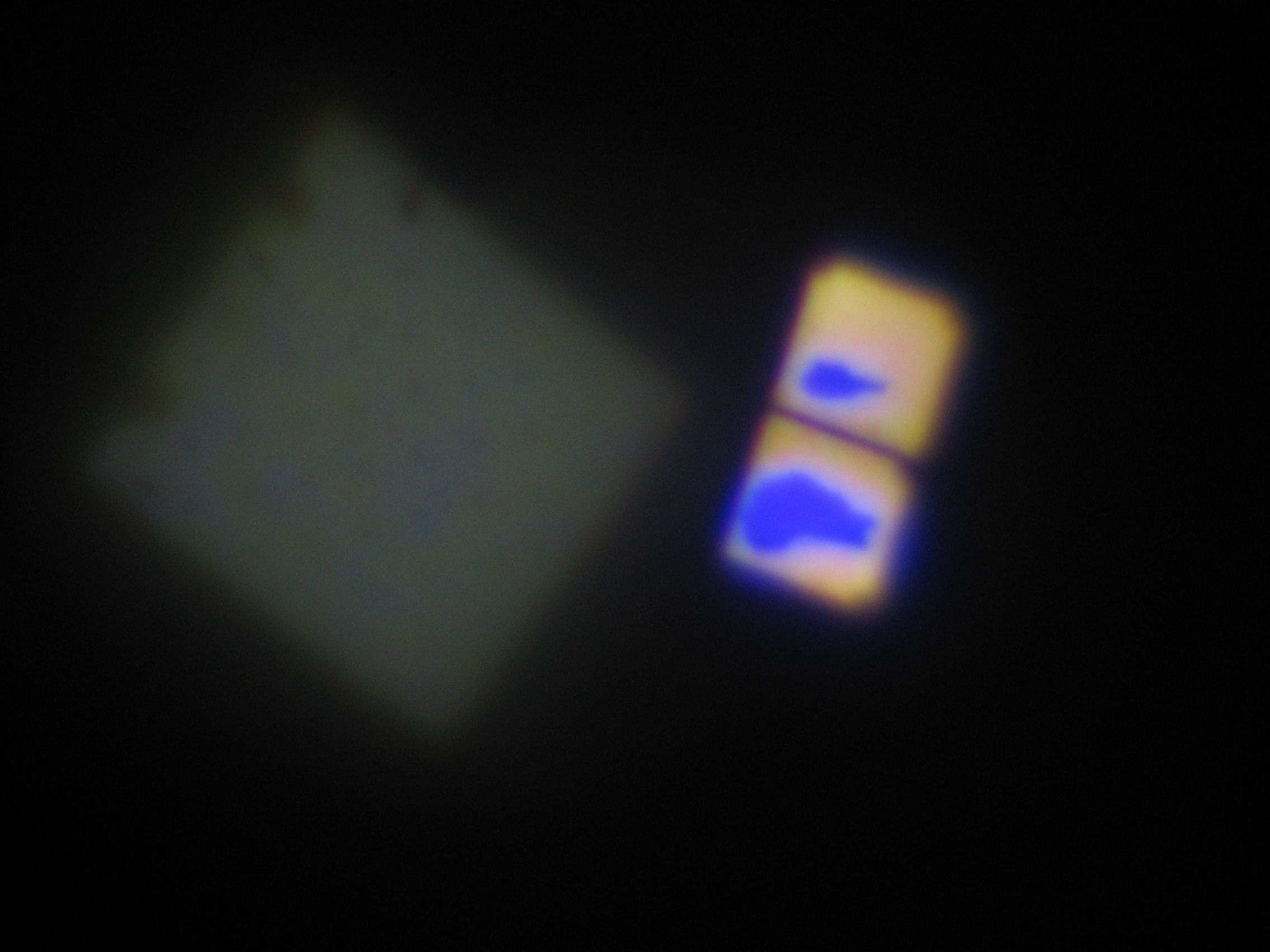
Before and after beam shots.
Left CNQ Zoomy Host with Ahorton, Nichia 219C and 12 x 7135, Panasonic charged to 3.9V.
Right Nut Light with DX driver
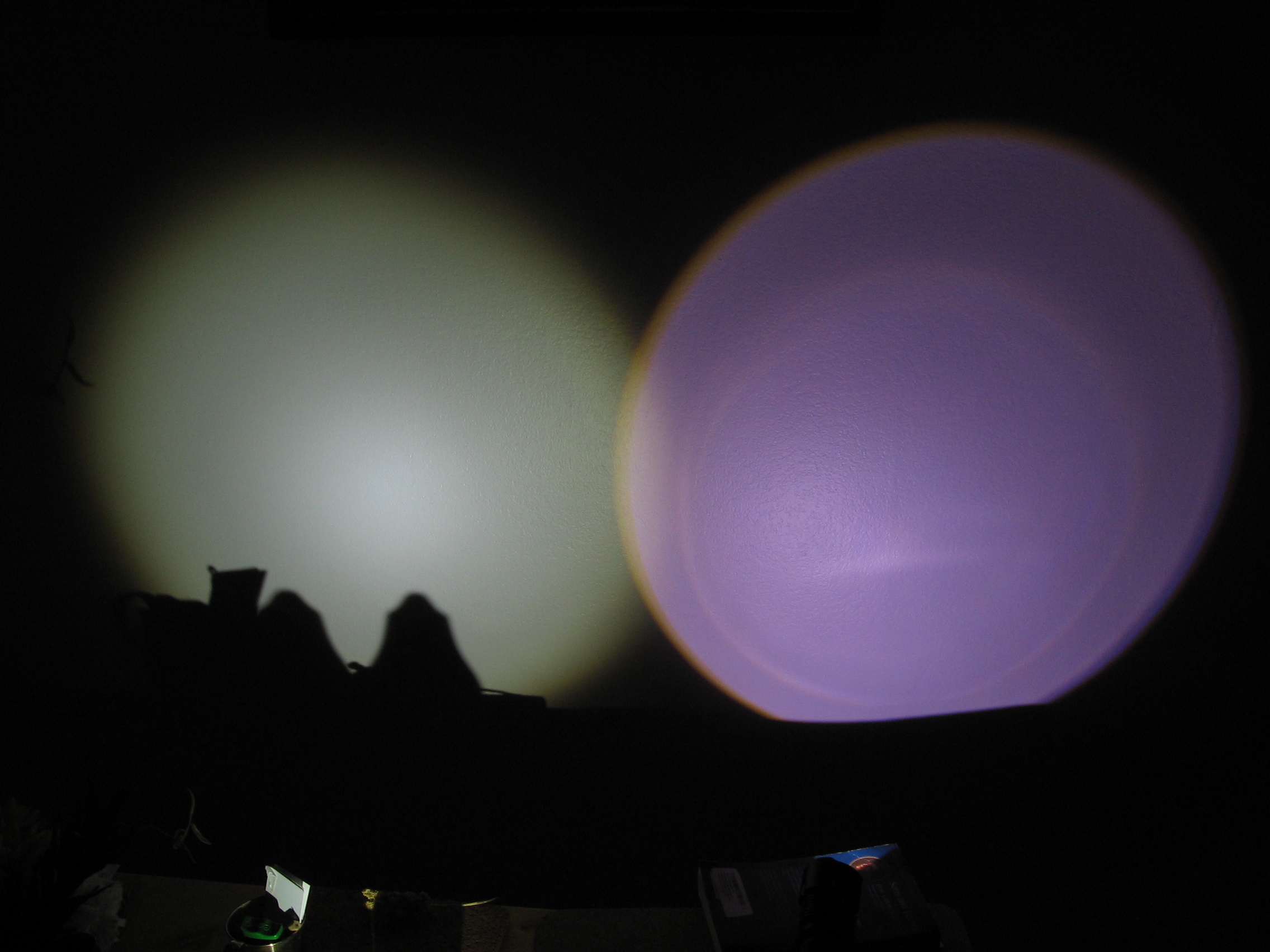
Left CNQ, right Nut with KD driver.
They are auto-focused on the Nut spot, so the change appears in the CNQ spot. With GIMP I estimate that the change is about 30, that is it is now 30 brighter with the KD.
It now draws 2.9 A at the tail in high mode from cells charged to 12.2 V. These are protected cells. When down to 11.3 V it draws 4.5 A. This current without activating the protection may indicate that the drain is fairly constant when driving the LED. With 800 mAh cells, that gives around 10 or 15 minutes run time.
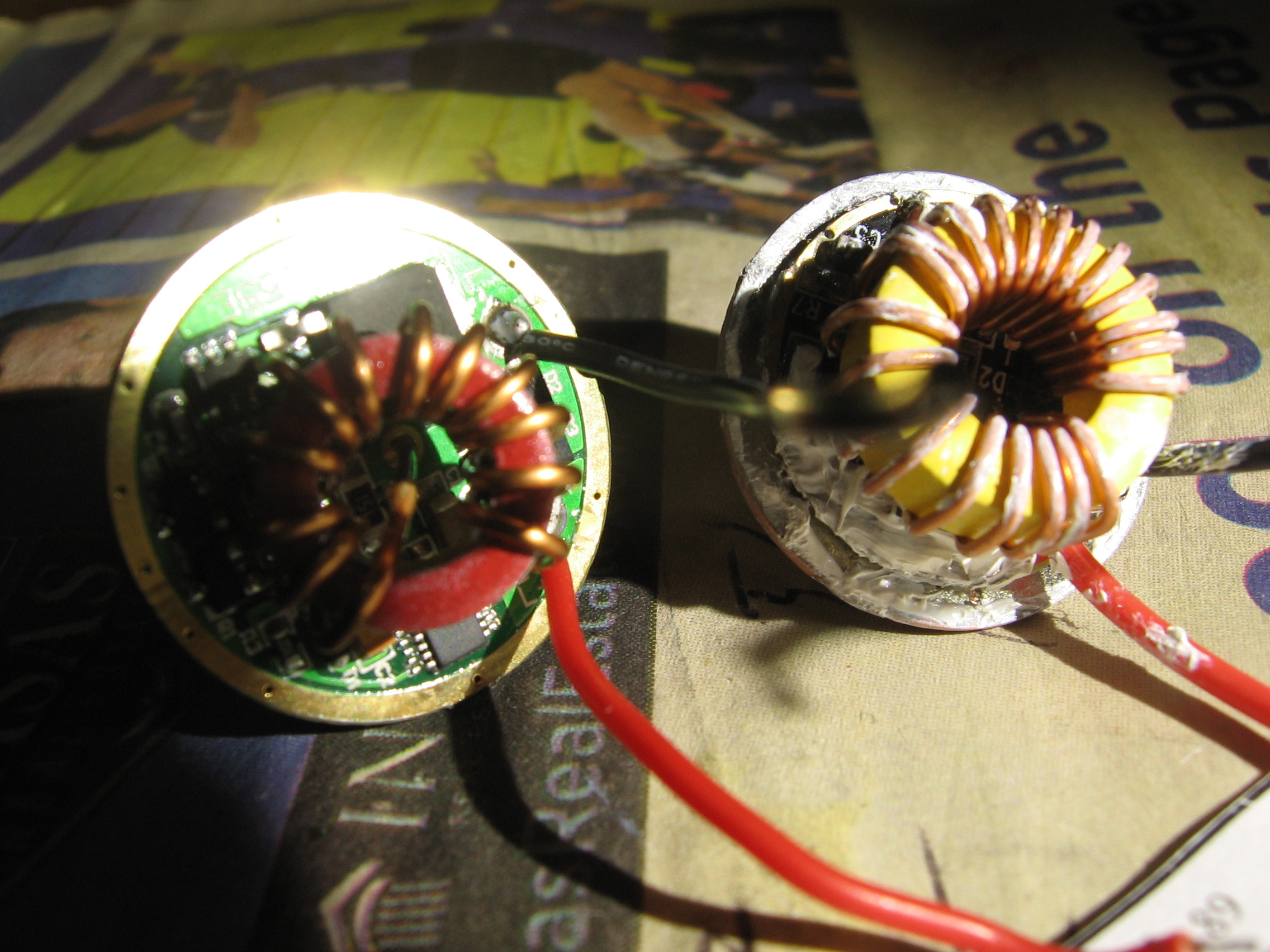
Here are the two drivers. The DX is partly potted with thermal paste.
Starting with this driver, the mod. is fairly straight forward, the only extra work being to crimp the back of the pill down to 26 mm. The best estimate of the current I have is 3.7 A which is above Cree’s rating but still well below maximum output on direct thermal.