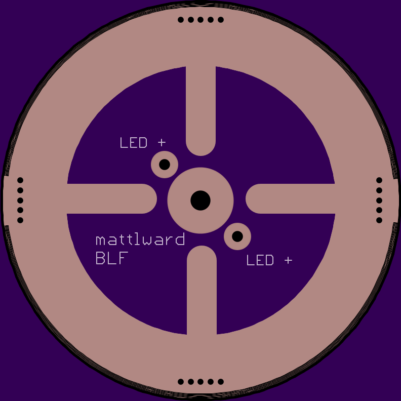
Ok, so I am going to have a set of contact boards made for this light. My idea is to create a board that will allow me to connect the BAT+ (center contact) of any standard 17-20mm driver thru the hole in the center with 12 awg wire to provide support and then to use copper strips to connect to the ground ring on the driver and to the ground ring on the contact board.
The current dimensions will require sanding to fit, but allow enough diameter to create the locking tabs.
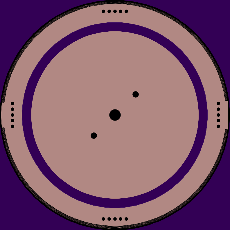
My questions… are there enough vias on the ground ring and are they large enough?
Comments and concerns welcome, this is my first board attempt.
Me, on the driver side, I would put a ( + ) Via ( up to 18awg ) in to run directly to the LED (+ ). And just a ( + ) pad in the center to power the mcu. Then bring the ground ( - ) in on 4 heavy wide traces to the center like a cross to within say 10mm of your center ( + ) pad. Then you can adjust for any size driver? I also drill and tap the body to secure the contact board down, utilizing the locking tabs, due to the press fit contact board and the battery tube will not secure it. Just a thought?
Matt, congratulations.
I’m currently waiting for my Courui to arrive.
Would like to order some version 2 boards as soon as they became available at Oshpark.
Don’t have enough knowledge about the number of the negative vias, but a total of 20 vias seems like ok to me.
Perhaps some of the BLF experts could help you to finalize the board design.
Thanks for your effort.
Mozart
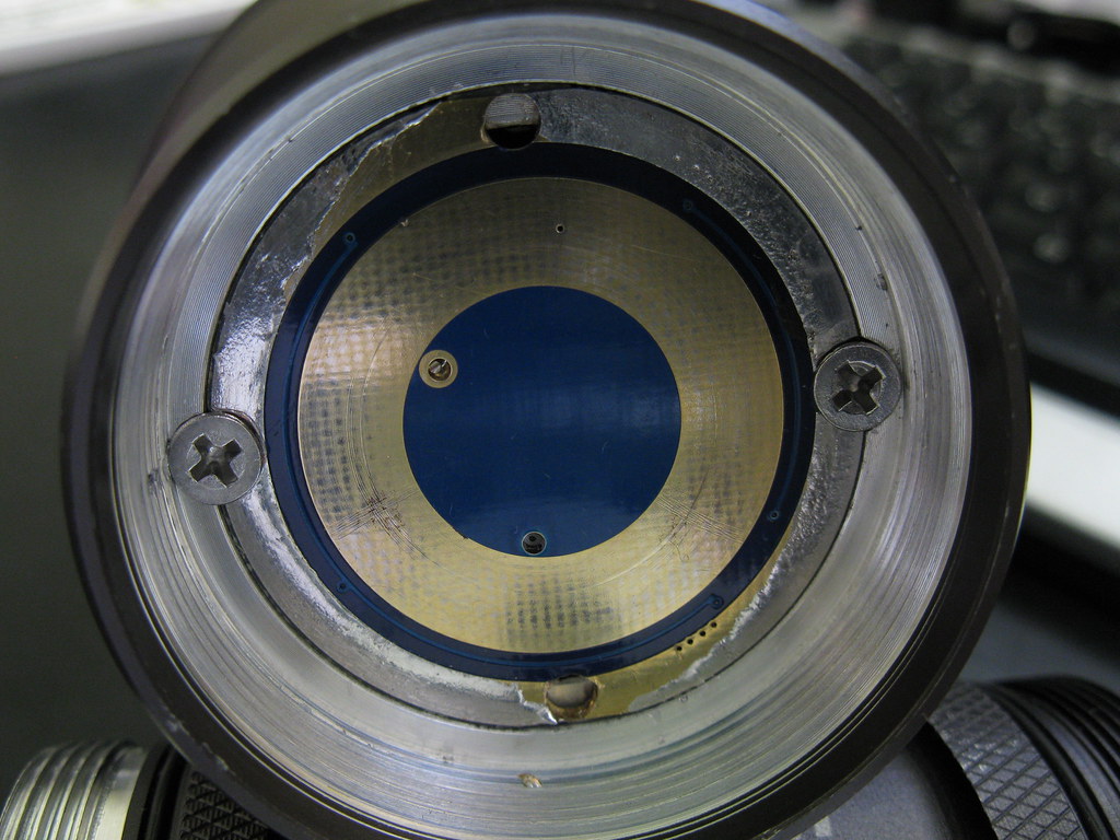
I think a big problem inherent with the D01(and many others) is the press-in fit of the driver/board, without any proper grounding. The first few DO1's I modded, I drilled through the 'ears' of the board, so it could be properly grounded to the body with machine screws, but there's not much room for error.
Where possible, I now use a dedicated ground wire from the body straight to the driver.
If you made the contact board a larger diameter (just under 43mm), so it sat on the ledge the screw heads are sitting on in the above picture, then the battery tube would tighten up hard against the ground ring, providing a solid ground.
A dowel (or possibly something attached to the other side that clips into the existing cutouts for the ears) would have to be used to hold the board in place/stop the board from spinning when tightening the battery tube.
I will do some fit testing this evening. If the battery tube will close on the added thickness on the outer ledge, then I like that idea. It would be easy to solder a small chunk of copper to the top side that would engage the old ear cut outs and prevent the board from moving.
Will let you know how that test turns out. I do not want to compromise the o-ring seal at the front of the battery tube in the process.
I have also had the idea of dropping on the basic set of components for a FET driver and forego the added piggy back driver. But, not everyone wants the same driver... So, I think I will stick with a contact board design that makes it easy to add your own driver.
I want to find a 3 or 4mm brass ring that is 17mm in diameter to mount to the bottom side of the driver. I think that would provide the most solid underside mount and would shed heat, for the top side of the driver I would attach 3mm x 1mm copper strap via solder to the contact board and the top side of the driver.
I am going to order soon, depending on the test tonight. I will only need one board, will likely part with a couple here once I have a build thread on it. Cost + shipping.
Why not both? These drivers are huge, plenty of room to do it. You can keep your current basic design, then just add the driver components off to the side a bit. MCU and smaller components in one of the triangles between the big ground “legs”, and the FET pad in a different triangle. That way if you want to use it as a driver, great. If not, you can use it as a contact board. It doesn’t cost any more from Osh.