SkyRC MC3000 modded with custom fans + testing

I received the SKYRC MC3000 about a week ago and have been extensively using it since then. Was very happy with the charger until I noticed a sudden current drop while discharging 4x18650s at 1A, this is because the charger drops the current when the “Systemp” hits 85°C, and adjusts the discharge power to regulate the temperature.

As some of you may know, the fan positioning and heatsink design is not the best for maximun airflow and efficient cooling. It works well for charging 4 cells at 2A and even discharging 2 cells at 1A, but 4 cells at 1A is a bit too much. I’ve been following the CPF thread and knew this would happen, so I bought it along with a couple 12V 5010S brushless fans (50x50x10mm) from GB.

Being a BLF’er, if something can be modded for the better, it should be done.

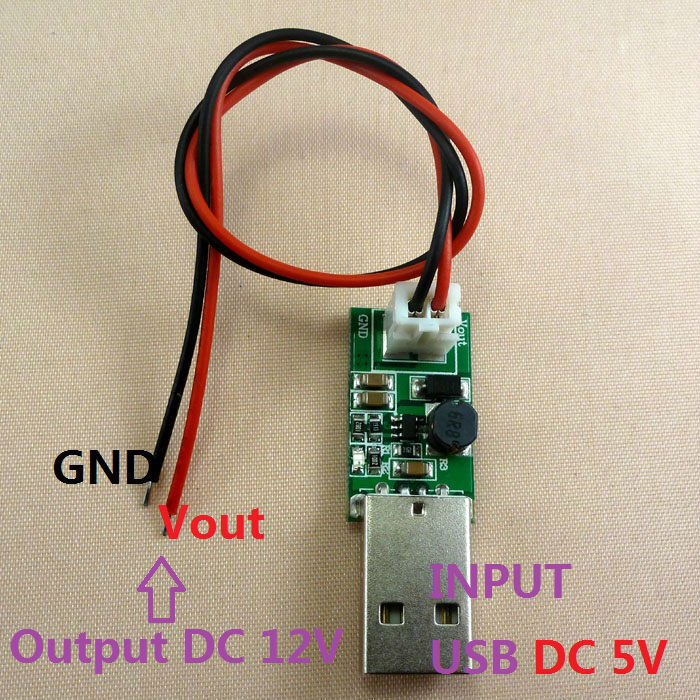
This mod consists on wiring the two fans directly to the power input with an in-line switch. They only need to be turned on when doing discharge tests. These are 12V fans but I think they can take 15V, overdriving by 25% is not that bad but sure it will affect the work life. However they are cheap and easy to replace.

It starts with disassembling the charger, relatively easy thing to do. There was some glue holding the flex connectors.

It uses an aluminium heatsink with 4 mosfets to burn the power. Can’t be seen very well but they are behind the toroids. Also notice only 3 of 4 FETs have thermal tape.

Test fit the first fan, I used a dremel to cut our the hole.

Now both

Omtem switch added on the bottom

Finished product

.
.
.
Testing #1
Setup: 1A Discharge 4x fresh Samsung 30Q. Room temp was rather low at 24C and the charger was placed on the floor which was a couple degree cooler.

At 81C I turned on the fans and Immediately the temperature started to drop. Because the fans pushes air in, the hot air from the heatsink got into the battery temp sensor and caused it to raise. BUT don’t panic yet, this is only a fake reading and it regulated back to normal reading after the air temperature dropped to even levels. At the end of the video you see the battery temp started dropping back. In just one minute the system temperature was dropped from 81C to 57C.

At 25:57 the temperature normalized:

.
.
.
Testing #2
Same setup as usual, room temp was higher at 28C and the charger was placed on a table. A more scientific test this time.

At 28:00 the temperature normalized:

.
.
.
Notes:
-This mod is absolutely UNNECESSARY as the charger has internal temperature regulation and overheat protection, at the expense of constant 1A discharge rate. Doing this will void your warranty, obviously.
-Putting everything back together was a real PITA.
-Now with the holes in the back the charger runs cooler. Charging 4x18650 1.5A does not even triggger he stock fan, temp remains at 43C.
-New fans are noisy, but quieter than the stock little fan.
-Did 2 C>D cycles with the new fans on, no problem to far.

PS. I also uploaded some of this info at the CPF MC3000 thread under my other username.

Nice looking mod. Sounds like it gets the job done too! Thanks for sharing w/ pics.

RE: the quoted text above, that’s probably not thermal tape. It’s an insulator: the “tab” on a MOSFET like that is connected to “DRAIN”. The charger wouldn’t work if all 4 MOSFETs had their DRAIN tabs connected together by shorting against the heatsink. I’d guess that the insulator might be fish paper, mica, or silicone (I don’t know - probably mica?). Since 3 are insulated, one can be not insulated to save a small amount of money and improve heastinking performance a small amount.

I think TK and I discussed in an Opus related thread the possibility of having some fancier fan control. It shouldn’t be hard to implement temp based fan control with hysteresis or a control loop like PID and get the fans even quieter than what you have now while avoiding annoying bouncy on/off/on/off behavior. Really it’s a question of motivation… but it should be so cheap and easy to implement that I’m almost motivated. Arduino Pro Mini clones cost ~$2 on eBay + a mosfet + a temp sensor if you don’t want to tap what’s built into the charger. I’d probably just use a PID library and include the stock fan’s power connection as an input on the Arduino which could override the control loop and set the fan(s) at max speed. It sure would be neat-o.

Good to see the effect of the additional fans!

Would you consider wiring the additional fans in parallel with the built in system fan? So that they are also fully software controlled.

Thanks for the explanation wight! I agree the cooling on these chargers can be easily improved, but it seems like it is not top priority to them.

Vex_zg, I also tought wiring them parallel with the stock fan but I’m not sure if increasing the load would cause any internal problems in the charger, since there is even a fan sensor that detects malfunction and stops the charger from working correctly. Stock fan draws 96mA and the aftermarket ones 150mA at 15V each.

There does seem to be some resistors and a small fet besides the fan connector, maybe that’s the controller and maybe someone with more experience in electronics can confirm if this is doable.

But for regular charging the stock fan works well, even at 4x 1.5A. The charger + adapter have a efficiency of ~68%, P-in 34W and P-out 23W, most of the loss is in the adapter.

Did you try connecting the two fans in series to your 15V Power input? Thereby under-driving them considerably, but they should still function, and move much more air than without…
Also, it would be more quiet, and good for the longevity of the fans.

Installation of those fans looks great though! Now order a set of these to dress them up:
http://www.amazon.com/Silver-Metal-Protector-Finger-Guards/dp/B00HPK8DNY/

The stock fan is a 2-wire unit, right? Have you tested the fan-failure detection? Does it detect a stopped fan when you manually stop it, a missing fan when you unplug it, or what?

@keltex78 - good point!

Tried wiring them in series but they just barely pushed any air, at 7.5V the current draw was only 60mA. Also I read somewhere that is not ideal to wire brushless fans in series.

I have not tried intentionally stopping the stock fan but the manual says something about fan current flow detection…

Found these on ebay, there is plenty of blank space inside the charger I think it can be placed in there. True temperature controlled fan! Need a way to regulate the input to 12v though:

Or go with the easy way: regulate the fan voltage to 10-12V using a 5V to 12V step up, or 15v step down converter.

Of course by removing the USB connector and wire it from the inside.

Step up: http://www.ebay.com/itm/mini-5W-USB-to-12V-DC-DC-Step-Up-Converter-5V-to-12V-Power-Supply-Boost-Module-/271843152682?hash=item3f4b1d532a:g:im8AAOSwstxVM5UJ

and step down: http://www.ebay.com/itm/2pcs-Super-Mini-DC-DC-Converter-Step-Down-Module-Adjustable-1V-5V-12V-16V-for-RC-/131036003817?hash=item1e825abde9:g:dcQAAOxyRNJSc0ht

As of now the new fan system is total overkill, I want to reduce the performance and increase the longevity while keeping the temp under 45C where the stock little fan kicks in because it is annoyingly noisy.

Now that’s a big hack, i beat you are not going to have heat problems.

Hi there will34! I stumbled across your fan mod while googling the SkyRC MC3000 and I registered here on the site just to first of all thank you for the inspiration as well as to ask a few questions that I’m still unsure of regarding the modding process.

1 - For the Omten switch: Can you possibly link me to the kind that you got? Or at least a fairly similar one? I only ask because I know they come in different form factors and I wanted to get one as close to the one you have as possible.

2 - As far as wiring the fan leads to the power input: Do you happen to have any pictures of this? My charger and fans are on the way now so I can’t take mine apart to look because I don’t have it yet and I just want to make sure I’m wiring it to the correct location and on the correct contacts.

3 - The only step in this mod that I haven’t had experience with before is the step-up and step-down converts. I understand what they do and following the links you provided I can figure out the step-down converter, however, the step-up converter allows me to keep the connector on the fan’s leads and just plug it right in. The less soldering I have to do the better lol. So with the USB step-up converter you linked, I understand that you would just plug the fan into the connector (of course while making sure that the + and - leads match up with the ones on the board); and I also read that you have to “remove the USB connector and wire it from the inside.” This is the part I’m unsure of. I think I can manage getting the USB connector removed, but I don’t know where the contacts that come from the power source need to be soldered at.

Any information and help with these questions from anyone would be greatly appreciated! Thanks again for posting this!

Welcome to BLF! :slight_smile:

Real omtem switch Omten 1288 Small Reverse Clicky Switch
Cheaper alternative: http://www.mtnelectronics.com/index.php?route=product/product&path=25_83&product_id=668

Plenty on ebay as well.

For the wiring, I decided to wire them directly to the DC input instead. The stock fan is FET-controlled with on/off sensor and I didn’t wanted to mess with the internals of the charger. The fans were rated for 12V but so far 15V of input hasn’t killed them… But of course a regulator would be a much better idea.

If you want to use the step-up converter, you must remove the front circuit assembly where the USB port is on, and then solder - & + wires to the back of the USB port to the converter with an inline switch, then to the fans. This is a bit more difficult, but will give you true 12v output for the fans regardless of the DC adapter being used. You don’t need to remove the usb port from the charger, just from the converter board. http://www.ebay.com/itm/mini-5W-USB-to-12V-DC-DC-Step-Up-Converter-5V-to-12V-Power-Supply-Boost-Module-/271843152682?hash=item3f4b1d532a:g:im8AAOSwstxVM5UJ

OR…

You could simply leave the wires outside the charger and connect the usb module whenever you like. not as pretty but this would be the easiest method.

Thanks!

Ok so just to be sure I understand correctly:

Solder + from USB port on the charger > Omten 1288 > DC-DC Converter > Fan.
Solder - from USB port on the charger > DC-DC Converter > Fan.

Does that look right? And if it is, do I need 2 of the USB DC-DC Converters?

Yeah that’s what I meant :wink:

Thanks for the quick response! I look forward to your next :slight_smile:

EDIT: 1 more question. What gauge wire should I use for connecting all of this? Figured I may as well grab some wire when I get the switch as I saw they sell wire as well.

The wiring is correct, you can place the converter on the bottom near the stock fan, plenty of room there. If I remember correctly my fans overdriven at 15V were drawing close to 200mA each, the ebay converter says it puts out 370mA with 5V 1A input, so I think 180mA per fan is more than enough at 12V. Anyways make sure by looking at the specs of the fans. My setup is way overkill dropping the temp to below 45 Celsius, the charger can work comfortably at 60. I used 24AWG since the current is very low.

Also remember the position of the sliding trays when taking the charger apart, putting them back together was a real PITA.

Looks like the fans I got pull 150mA or so each so that’s at least 300mA so I guess I should be good with the one. I decided to get some fans that would last a bit, pull lots of air, and be quiet. Was a little less than $16 total for both. It uses a Hydro Dynamic Bearing so it’s able to get to high RPM while both being quiet as well as having a longer lifespan.

Haha I’ll definitely keep that in mind!

Awesome! I’m pretty confident on what I need to do now and how to do it. Thank you so much once again for sharing and especially for responding to me after I revived a bit of a dead thread. I sincerely appreciate it!!! :smiley:

I signed up specifically because i’m considering purchasing this charger and one of my hangups has been the tiny cooling fan which reminds me too much of the one on the Opus 3100. Its good to see someone who thinks the same way as me and ignores warranties in order to improve a product. :slight_smile:

My only criticism of this mod is the fans you used. If i’m spending $100 on a charger only to cut it up and hopefully improve its functionality, i’d be using some proper ball bearing fans that were 5v like these: https://www.amazon.com/DC-Fans-50x50x15mm-5V-Fan/dp/B0131UPA6Y/ref=sr_1_86?ie=UTF8&qid=1466835886&sr=8-86&keywords=50mm+5v+fan
Actually you could get by using much lower air volume fans because of the lack of exhaust vents in the case since you can only over-pressure the case so much before you start putting undue stress on the fans and creating additional noise. Its hard to find quality fans in 50mm size and since 60mm is too big, i’d probably go with 40mm 5v fans and run them without external power. These Noctua fans are as good as money can buy and are very quiet. https://www.amazon.com/noctua-NF-A4X10-FLX-5V-Noctua-Fan/dp/B00NEMGCIA/ref=sr_1_2?ie=UTF8&qid=1466838059&sr=8-2&keywords=40mm+5v+fan
Those little guys only draw 0.05a and are 17.9dba so they’re super quiet. They’re also made in Austria and have a 6 year warranty.

Welcome to BLF, well if you plan to get this charger and use it for discharge test I belive the fan mod is a must to keep the temperature to acceptable levels.

I used the cheapest fan this size I could find at the time and so far they have been working great, they do make some noise at 15V and I didn’t use expensive fans to keep the cost down, this is budgetlightforum after all. The case has enought holes for the air to scape, mostly from the bottom.

However if I were to do this mod again, this is what I’ll do differently:
-Use a DC-DC step down regulator and set the fan voltage to around 10V or less to reduce noise and airflow. Actually I have a couple of these, I should probably install one.
-Seal all four battery temperature sensors so when the fans kick in it doesn’t blow hot air into those sensors.
-Probably try a push-pull setup

These cheap fans are actually quite nice, with the correct voltage they make very little noise. Those noctua fans you linked are even better but way overkill in my opinion.

And while you have the charger dissasembled, reinforce the spring post to avoid breaking, which is getting common with this charger. Let us know how it goes…

will34 - awesome mod! Sorry to dig this up from the graveyard but I can’t seem to understand how you’ve connected the fans to power.

How’s the system working - fans still going strong?

How have you actually mounted the fans? I don’t see any screws.

How are you connecting the fans to power such that they don’t come on when the system is powered, or the switch you added also controls system power?

Thanks!!

The fans are connected directly to the DC input port with an inline switch on the bottom of the unit, and they are mounted with hot glue from the inside. I only turn them on when doing discharge tests.

The fans are holding up great so far, I didn’t expect them to last this long being overdriven and once I even accidentally left it running for several days and they were just fine.

If you are going to do this mod I strongly suggest you to have the fans blowing air out instead of sucking air into the unit, because it will push the hot air from the heatsink towards the battery sensor throwing a wrong temperature reading. Now that I think about it there are way better ways to mount the fan to make it easier to replace.

For longetivity of the fans I would use one of those cheap DC-DC buck converter from eBay and sightly underdrive them.

Wow! Nice mode!
Need to add fan grill, like this)

will34, I met complaints on the forums that the battery temperature sensor is lying and lowering the temperature by 20 degrees. Are you able to do this ?