I think I’m having an issue with this driver, maybe I’m wrong. It’s FET driver (http://www.mtnelectronics.com/index.php?route=product/product&path=67_117&product_id=227) installed in Brinyte B158 and it drives an XP-G2 dedomed led. I wasn’t aware of the thermal protection in these drivers, but this sure looks like one. Three blinks and a step down should be the indication of low battery protection kicking in. Please correct me if I’m wrong and explain what is happening here. After the step down the temperature of the driver was about 50 degrees Celsius. A Multimeter on the left measures voltage of the battery and the one on the right measures Amps. Please watch the video, it’s not long.
lol. is the driver in the pill? Have you run the pill in a flashlight and had the same results? Without the flashlight the pill will get ridiculously hot in seconds
Yes, the driver is in the pill. It doesn’t get ridiculously hot, it gets up to 50 degrees. When screwed into the body this happens in about a minute. Step down kicks in at about the same temperature.
Do you have the standard clicky firmware? Is it possible there is a bad connection dropping a bunch of voltage and the driver is actually seeing 3V? I don’t think this could be, actually, because I think that LED needs more than 3V to run at 2.5A.
The description does not describe any thermal protection features, except for the turbo timer. Maybe the voltage sensor of the driver is reading way low so it thinks it is at 3V and steps down.
The driver you listed doesn’t have thermal regulation so it has to be a voltage issue causing the step-down. How does it act with a fully charged battery?
Yes, it’s a standard clicky firmware with no turbo timer. I also suspect at the voltage sensor. When I manage to squeeze some free time I’ll redo all the contacts.
It is the same. I get same results at 3.5V, 3.8V and 4.2V. When I tried it for the first time my battery was low (around 3.5 V) and I thought that it must be low voltage protection but it happened at every voltage.
Could you please be more precise? Where should I put “+ lead” and where does “- lead” go (sorry but I’m no electronics guru )? At what point should I measure this? When the step down kicks in?
Where do you measure voltage? You need to measure directly on the mcu pins like comfy suggested. You can as a first step measure on the driver and it’s important to measure the + also as near as you can go to the PCB with your probe(the spring has also a voltage drop)
Every cable and every spring and everything which has a current flowing through it has a voltage drop…
The forward voltage at 2.6A for the XP-G2 is 3.29V, so this is the voltage at the LED. The voltage at the MCU should not be lower than this, correct? So it seems there is significant error in the MCU voltage reading if it is triggering the 3V low voltage step down.
The behavior your light is displaying (3 blinks then stepdown) is consistent with a bad ground connection between the driver and pill. I’ve experienced the same issue with the same driver and it was always the ground connection.
Check to make sure that the negative ring on the driver is connected firmly to the sides of the flashlight’s pill. You may need solder the driver into the pill or install extra solder braid around the edges of the driver to improve the connection.
You can also just jumper pins #8 & #7, this will override the voltage divider and essentially disable low voltage monitoring. Run it until it starts doing the step-down thing again, then stick a small screwdriver blade between the two pins.
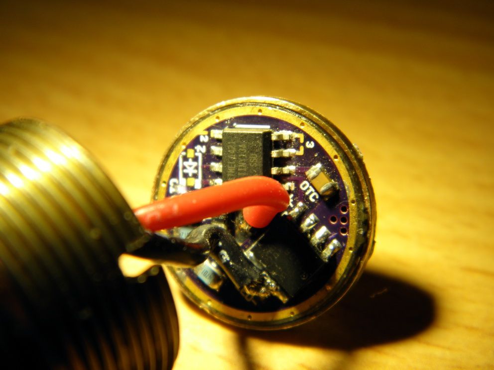
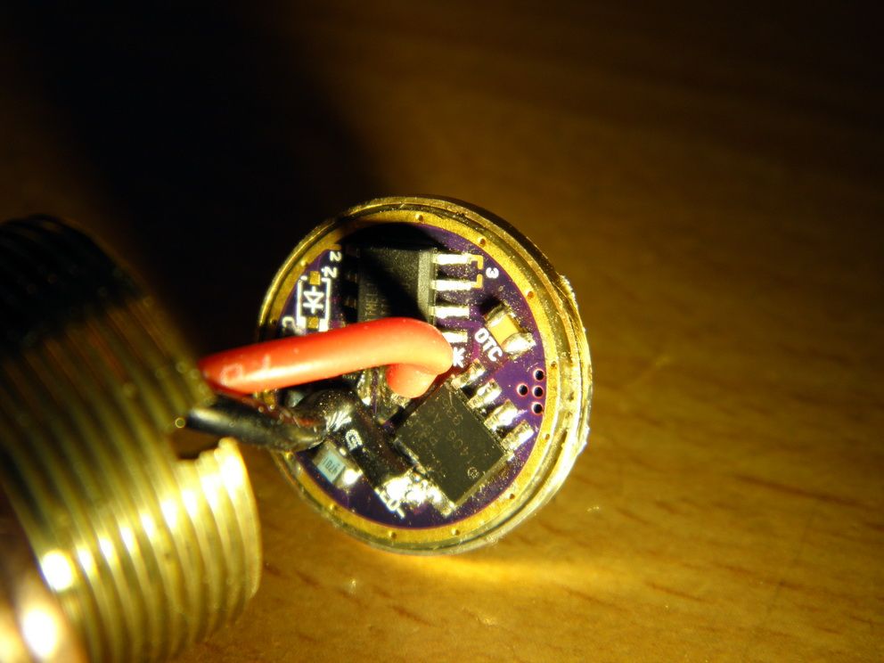
Can you post a clear, closeup pic of the driver so we can see which components got put where? Richard's good but nobody's perfekt.
Which MCU pins? Please point or explain. Comfy said pin No.7. Where should I put other multimeter lead? Should I measure when light on or off? Should I measure when step down or before?
I’ll resolder driver-pill connection in the morning. I did try this: took the driver out of the pill and made the contact with alligator clip directly on the drivers ground ring (bypassed the pill driver contact). Same problem. To be sure I’ll resolder everything tomorrow morning when I’m fresh. Thanks.
Please point or explain pins #8 and #7 on the MCU so I can find them. After I jump these pins what is going to happen?
pin7 measures the voltage so you should measure between pin7 and GND (pin4).
The two blue resistors are a voltage divider, they divide the voltage so that the mcu can handle it. That’s because the mcu ADC can only measure up to 2.5V or so…
Check out the schematic(your driver has no 7135 but the voltage measuring is done almost the same with all drivers just the resistors have different values here and there).
R1 and R2 divide the voltage and between them the line goes to pin7.
Comfys idea to connect pins7 and 8 would give full voltage on the ADC so that the firmware would think that the battery is super full and no step down is made.
Do what you did in your video. When it steps down, turn it off, jab a pointy metal something or other between pins 7 & 8, then turn it back on and let it run again. Does it still step down? If not, and it goes back to stepping down again after you remove the pointy metal something, then you have a voltage monitoring problem, not a heat problem.
Measuring voltage between pin 7 & GND gives a less-than-obvious result. Since it's being fed by the voltage divider resistors, the voltage will be somewhere between 0 and 1 volt, depending on battery state of charge. I checked a few drivers and got around 0.775 and 0.785 volts at pin 7 with a fresh battery. But, what that voltage should be depends on the resistors used and the firmware currently in the driver. There is no one correct answer for what is a good number and what's a bad number.
There is no step down after shorting pins #7 and #8 :-). When short is removed step down kicks again. Should I short them permanently and lose LVP or there is better solution?
Talk to Richard. If nothing else, I'm sure he'd like to get it back and figure out what went wrong. Int'l shipping may make that impractical though.
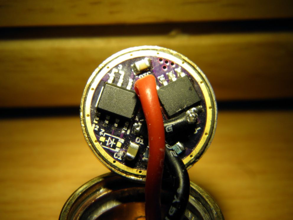
Just in case it's a hardware issue, can you get a clear straight-on picture of the driver, without the wires hiding the important bits? It could just as easily be a firmware issue but without a good pic to verify the parts are in the right places it's hard to say. Bend both wires over across the top of the FET, we all know what those look like. ;)
If you want to just use the driver and make it not step down (and are OK with losing low voltage protection which already doesn't work), remove the '4701' resistor.
I can’t thank you enough comfy . I’ll unsolder the wires tomorrow (can’t bend them enough), post the picture and hope it is a simple solution. If not I’ll probably use it as is.