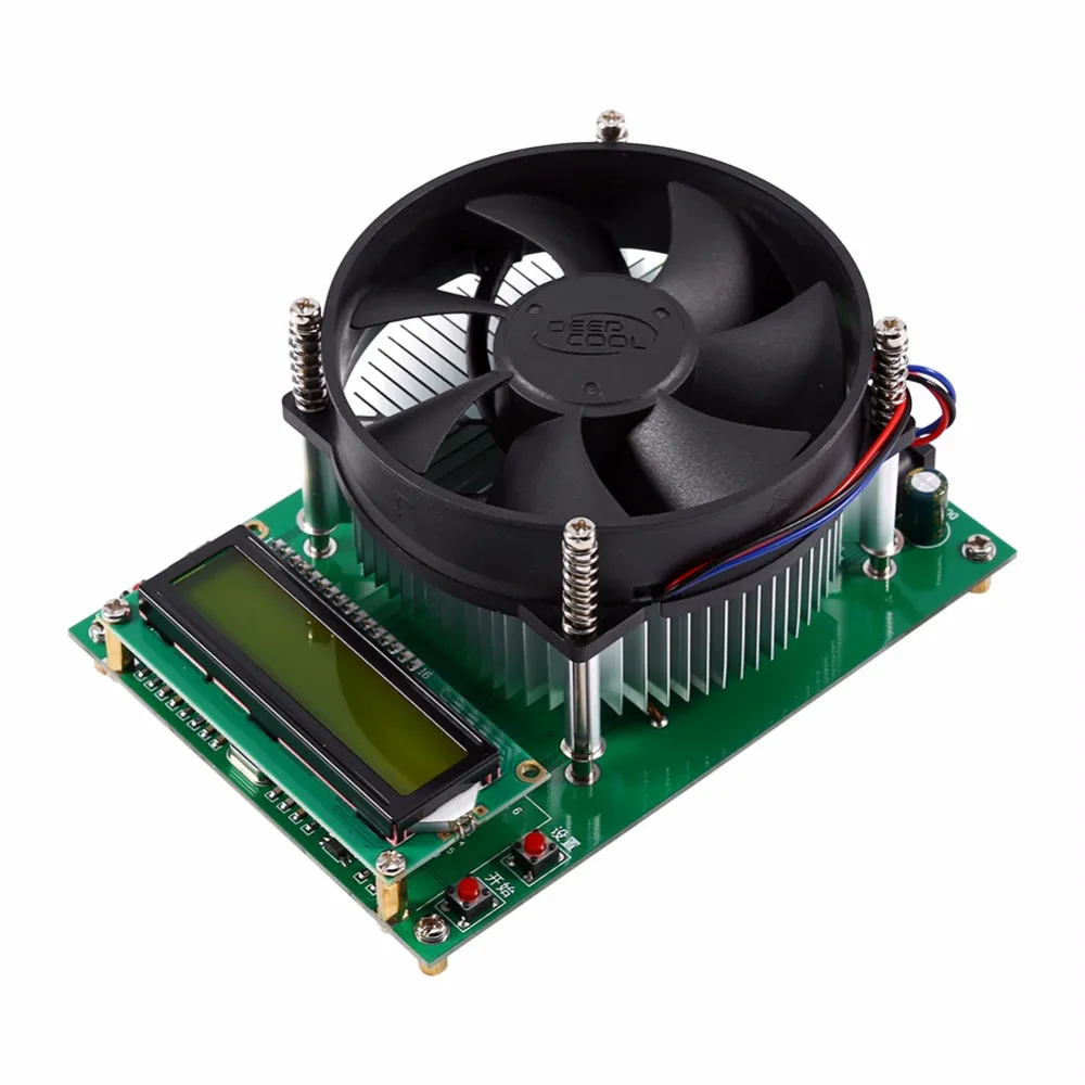
Electronic load 60W
Official specifications:
-
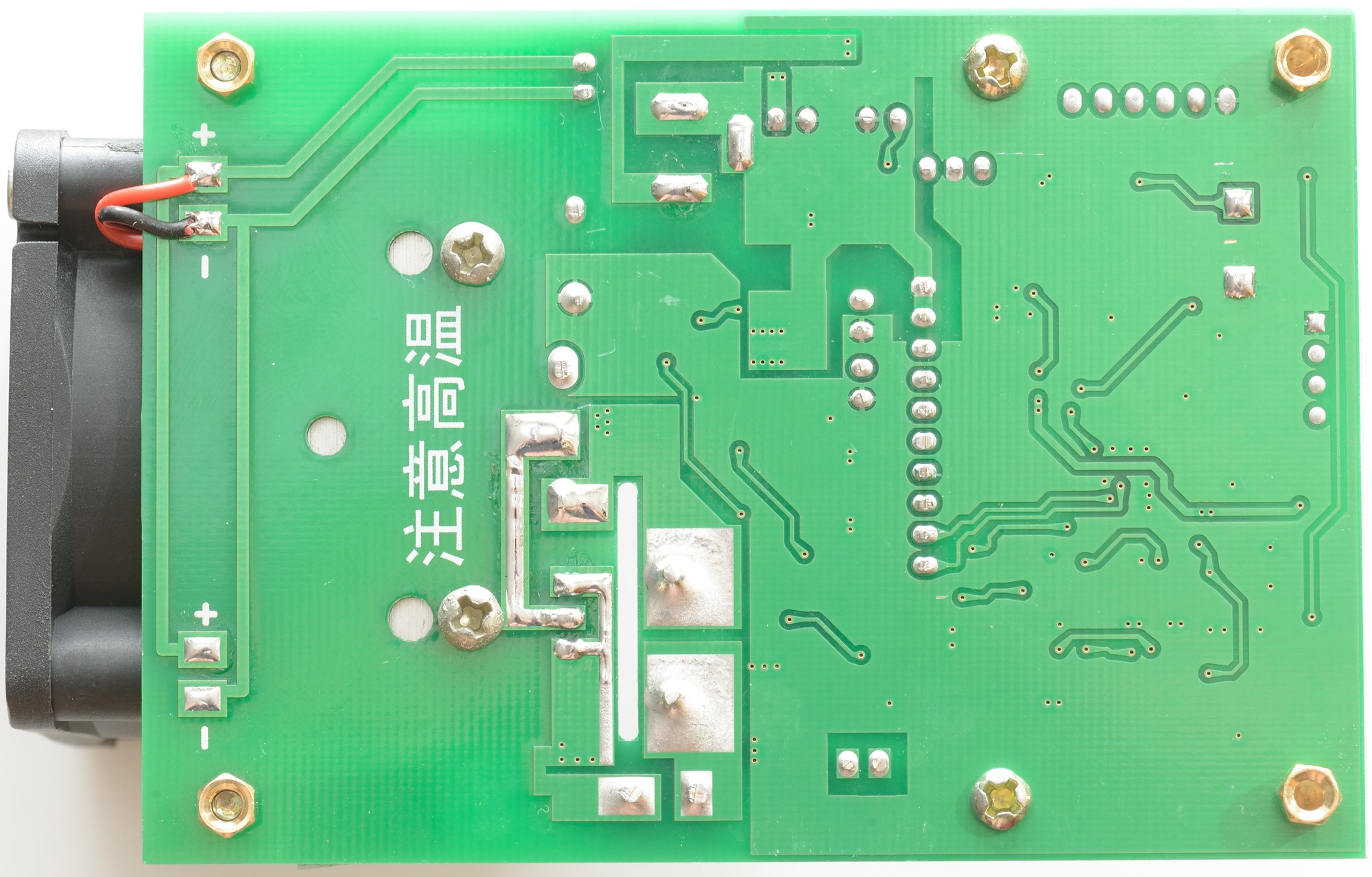
Board size: 100mm x 70mm x 57mm (fan prominent board about 12mm)
-
Positioning hole location: 60mm x 88mm , hole diameter is 3.2mm 5mm pedestal installation
-
Working Power requirements: DC12V
-
Operating mode: Single-mode constant current (CC)
-
Discharge current: 0.20-9.99A stepper 0.1A or 0.01A
-
Discharge current maximum error: 0.7% –0.01A
-
Maximum capacity test error: 0.5A 2.5, 2A 1.5, 5A and above 1.2%
-
Offline (termination) Voltage Range: 1.0-25.0V stepping 1V or 0.1V
-
Discharge voltage: 1.00-30.00V
-
Maximum voltage measurement error: 1% + - 0.02V
-
Maximum power: 60W super power automatically limit the maximum current
-
(for example, up to 60W when it can start 9.99A 6V and 20V maximum can only be opened at 3.00A)
-
Highest battery test statistic: 999.9Ah or 9999Wh, reaches the value stop testing (in value by a first stop condition)
-
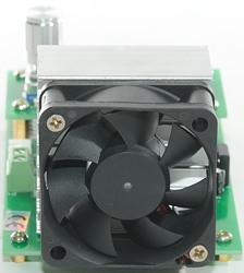
Fan control: intelligent fan control (fan can automatically according to the heat sink temperature infinitely variable)
I bought it from banggood.com

It arrived in an envelope without any documentation or accessories.
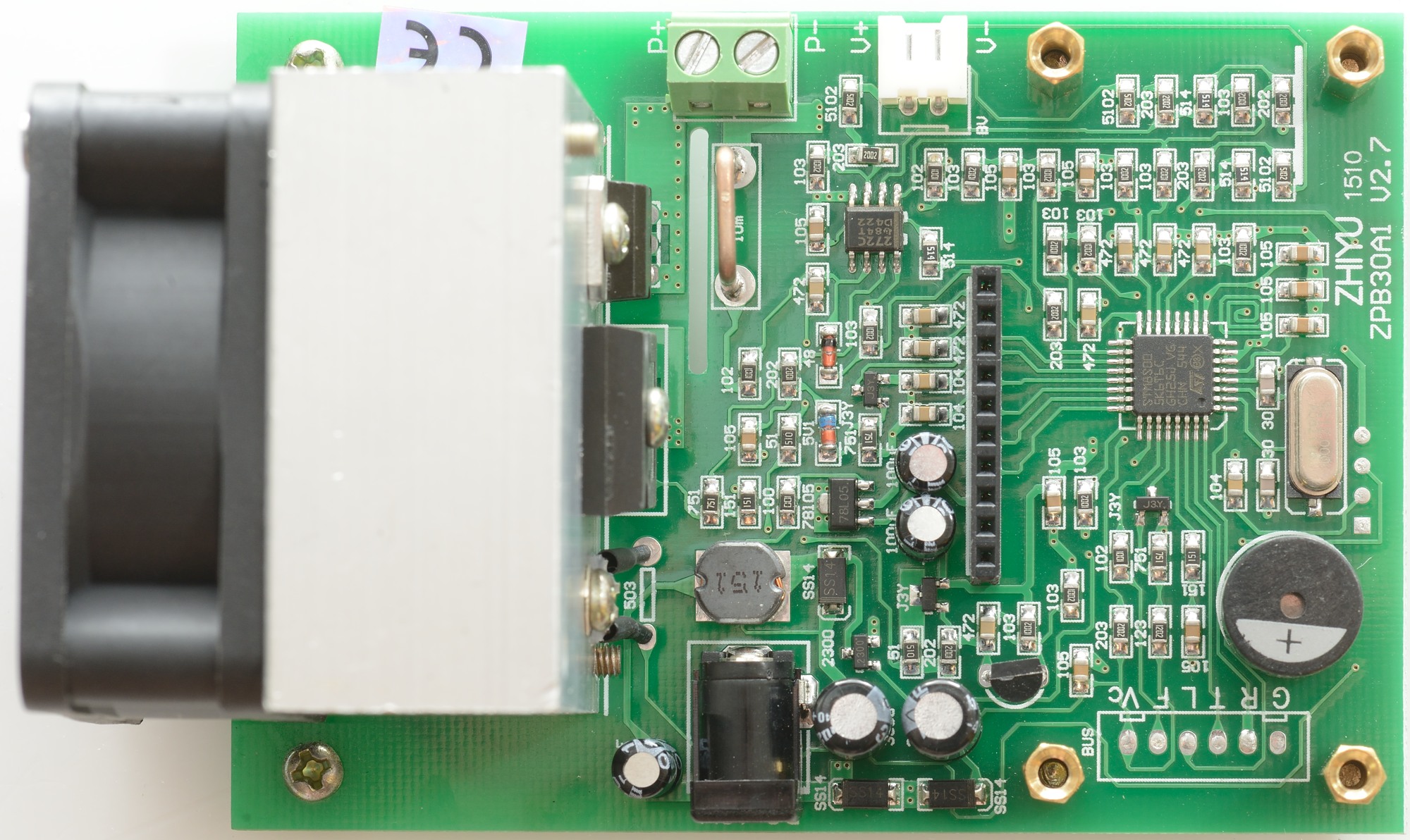
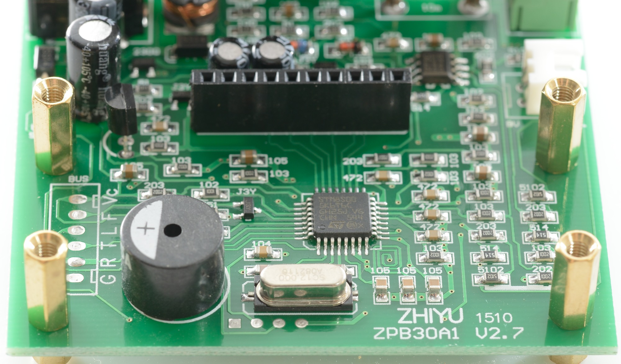
I checked the connector (BUS) with a scope: Vc: 12V, F: 50Khz at 5V, L, T, G: 0V, R: 5V. R and T is probably a 5 volt serial bus, but it is not sending data by itself.
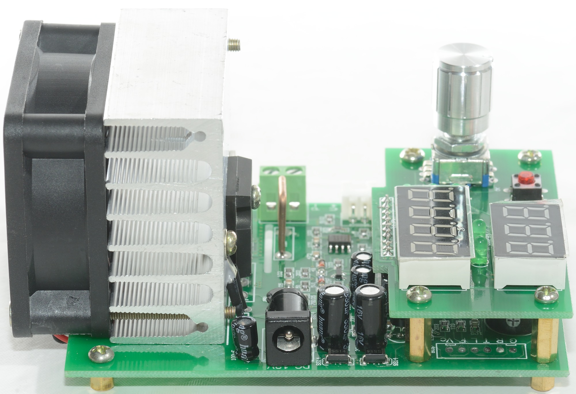
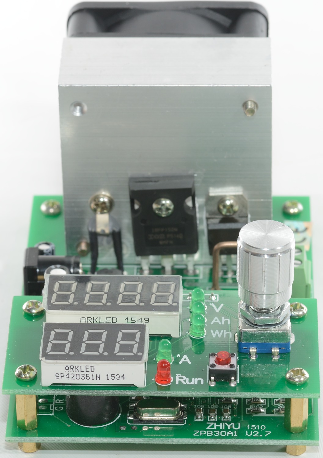


The two green leds between the display shows what digit the encoder is adjusting on.
There is some chips hidden under the display.
The encoder can both be rotated and pushed. Pushes are used to move between the four settings (0.1A, 0.01A, 1V, 0.1V)
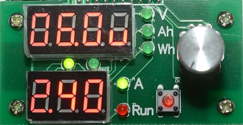
Here is the display from ready mode, when running the “u” will be replaced with one more voltage digit.
At the current time the encoder will adjust 0.1A setting, this is based on the two green leds.

Simple user guide
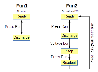
The load has two modes called Fun1 and Fun2. Fun1 is a simple load, Fun2 will calculate Ah, Wh and will automatic stop when the voltage drops.
To select mode: Hold “Run” down and apply power, now the encoder can be used to select Fun1/Fun2, press run to confirm. Next selection is beep on/off. When this is confirmed the settings are saved and the load is ready
In Ready mode the encoder is used to select current and voltage, click the encoder to change between digits and value.
Fun1
Pressing Run will toggle the load on/off. It is possible to adjust the current with the encoder when on.
If the voltage drops below voltage setting, the buzzer will sound, but the load will continue to work.
Fun2
Pressing Run will toggle the load on/off. It is possible to adjust the current with the encoder when on.
The top display will change between V/Ah/Wh.
If the voltage drops below voltage setting, the buzzer will sound, and the load will stop with Ah readout.
Pressing the Run button will stop the buzzer and change to readout mode, where the encoder can be used to select between Ah/Wh.
Pressing the Run button again will reset Ah and Wh, then return to ready mode.
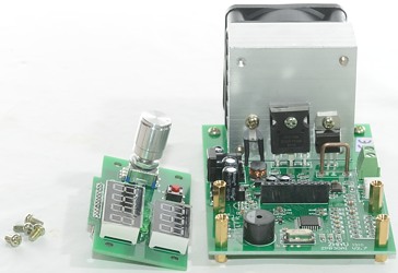
Accessories
To use the load some accessories are needed, I will recommend:
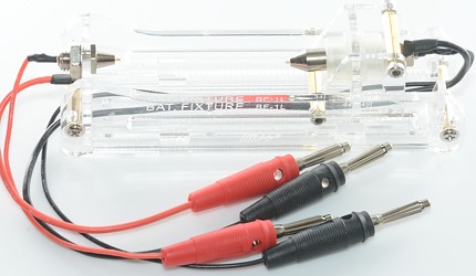
A battery holder, get the version without banana plugs. The thick wires goes into the screw terminals, the thin wires goes to the voltage sense plug.
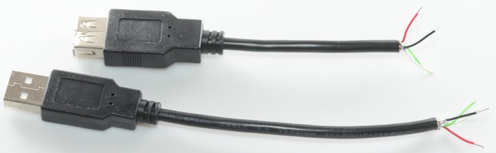
Cut a usb cable in two, connect the red and black wires to the load, this can be used to test usb power banks and power supplies.
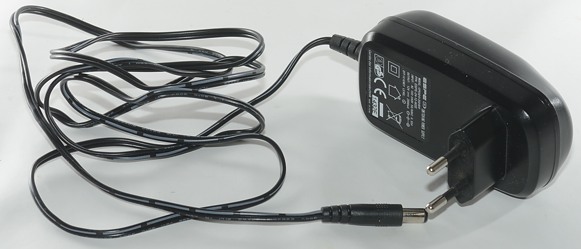
A 12V power supply with 5.5/2.1mm plug and this is not an optinal accessory, the load needs an external power supply to work,
Measurement
-
Will remember settings after a power cycle.
-
Current consumption from 12V when idle is 66mA
-
Current consumption from 12V when operating is up to 300mA
-
Load current draw when off at 30 volt is 0.37mA
-
Load current draw when off at 10 volt is 0.12mA
-
At 30V and 2.00A the current was stable within 0.15%
-
At 6V and 9.99A the current was stable within 0.2%
-
Readout is within specifications.
-
4 terminal reading can handle at least 6 volt compensation.
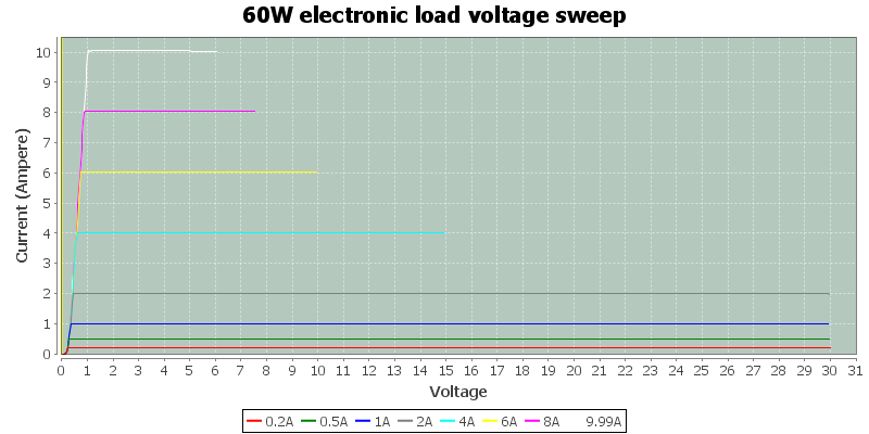
The current is fairly stable at different voltages and currents. It looks like it can work down to about 1 volt.
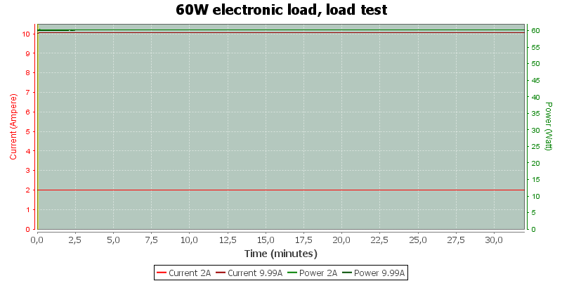
The current is also fairly stable over time/temperature.
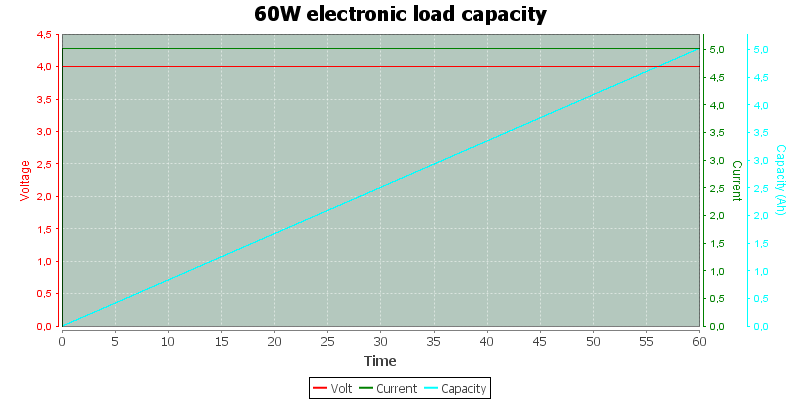
The above curve is from my capacity test, I did exactly one hour (Within 3 second) with 4V and 5A.
My supply showed it had delivered: 5,02639Ah and 20,1080Wh
The load showed it had received: 5.029Ah and 19.89Wh
I wonder why the load shows a bit high on Ah, it was adjusted to 5.00A and was supposed to show 5.00Ah (In reality the current was 5.02A and the reading is very close to correct).
I did not use 4 terminal during this test and the voltage at the load was 3.92V (According to the readout), this means the Wh readout was supposed to be V\*Ah -\> 3.92\*5.029 -\> 19.714Wh.
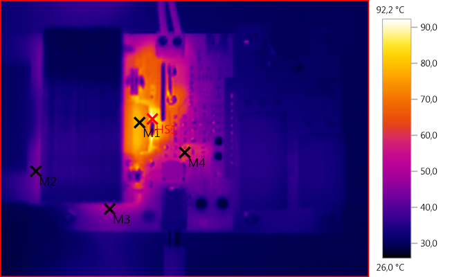
M1: 77,5°C, M2: 43,0°C, M3: 49,0°C, M4: 73,7°C, HS1: 92,2°C
The IR photo is from a 60W 9.99A run, the fan keeps the temperature reasonable.
The 78L05 regulator (M4) gets fairly warm.
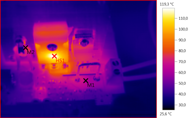
M1: 65,5°C, M2: 75,2°C, HS1: 119,3°C
The heatsink do not look hot on the IR photo, that is because it reflects IR. The temperature sensor (M2) tells the story, the heatsink is probably 80°C (I could have put a piece of black tape on the heatsink to get the real temperature with the IR camera).
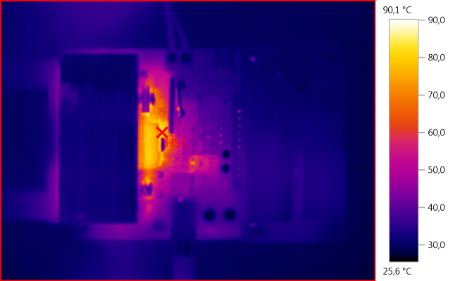
HS1: 90,1°C
This photo is also 60W, but with 30V and 2A.
Conclusion
For the price it is a very nice load and due to the external 12V power supply it can work from 1V and will not forget values.
It cannot in any way match a professional load that has many more functions (and cost much more), but for testing batteries, power banks, power supplies and even solar cells, it can be very useful.
The fan goes from off at low power to very audible at high power.
Precision is good and more than enough to check different devices/batteries.
Notes
I have seen this load with a larger heatsink and higher power rating (110W), current and voltage rating is the same.