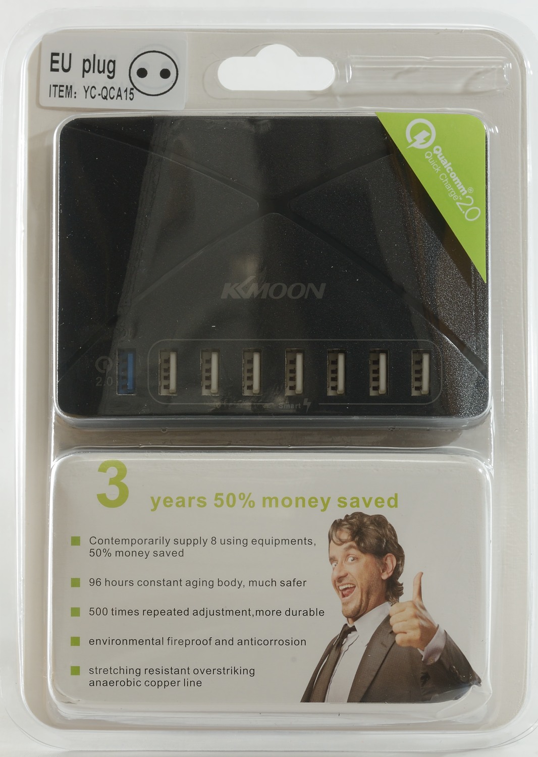
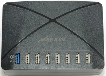
KKMoon 8 port YC-QCA15
Official specifications:
-
Brand: KKMOON
-
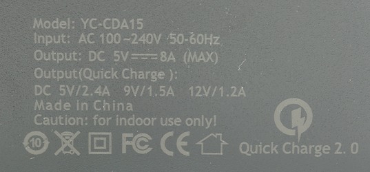
Model:YC-CDA15
-
Material: ABS+PC
-
Color: White, Black(Optional)
-
Input: AC 100-240v 50-60Hz
-
Output & Power (Universal): DC 5v/2.4mA
-
Output & Power (Fast Charge): DC5V/2.4A 9V/1.5A 12V/1.2A(Max)
-
Compatible with: for HUAWEI Mate 7 P7 P8 Samsung Galaxy Note4 Note5 Note edge S6 S6 edge S6 edge Plus LG G4 Xiaomi Note Pro
-
Smartphone, tablet
-
Product Weight: Approx. 201g / 7.0oz
-
Product Size: Approx. 11.5 * 8 * 3.5cm / 4.48 * 3.1 * 1.36in
-
Package Weight: Approx. 315g / 11.0oz
-
Package Size: Approx. 21.5 * 15.3 * 5.5cm / 8.38 * 5.96 * 2.14in
I got it on ebay from: tomtop_auction

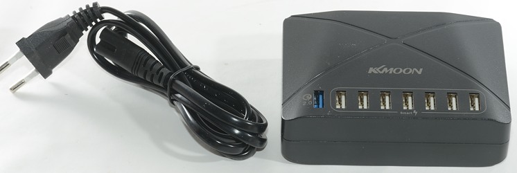
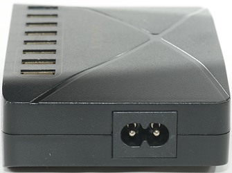
The charger and a EU power cord was included.
Measurements
-
Power consumption when idle is 0.26 watt
-
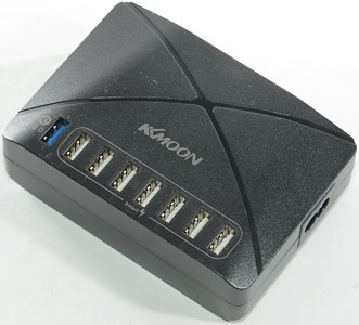
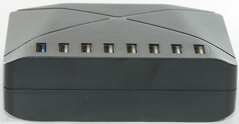
USB port #1 is Quick Charge 2.0
-
USB port #2 is coded as Apple 2.1A
-
All the other are usb charger (DCP)
-
All outputs are in parallel
-
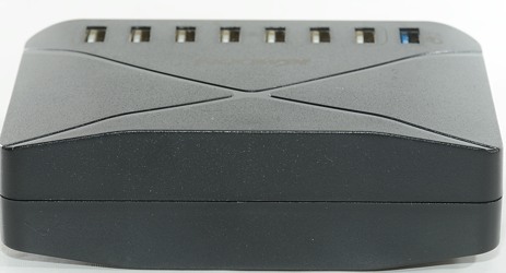
Weight: 190g
-
Size: 116x82x35mm
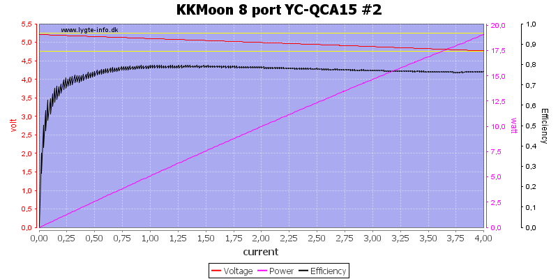
There is no overload protection on the individual ports and power is first feed to port \#2 (It has highest voltage at 4A load).
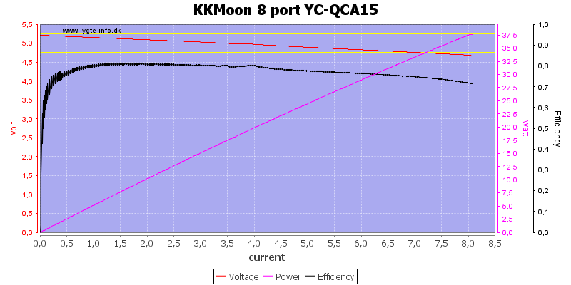
The charger is rated for 8A and it can deliver that and nothing more.
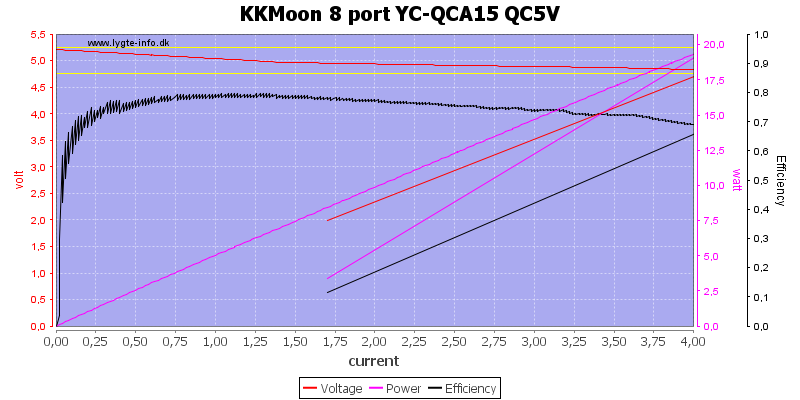
Quick charge can deliver a bit above 4A at 5 volt.
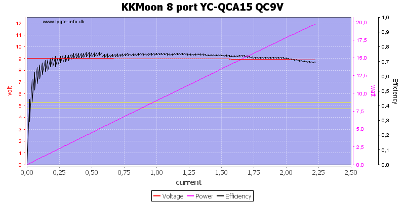
At 9V it is down to 2.2A
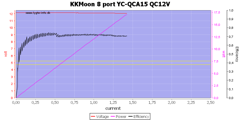
At 12V it is down to 1.3A. The efficiency is down to 70% here, not very impressive.
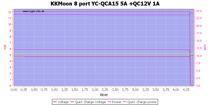
Lets try putting some load on all the channels and see how long it can maintain output, I started with 5A (out of 8A) on the normal usb ports and 1A (out of 1.2A) on 12V, it lasted a bit over 4 minutes before QuickCharge quit.
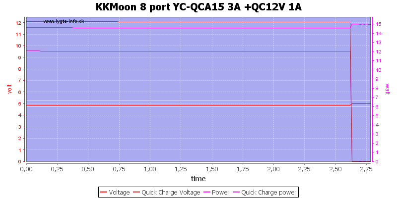
Reducing the normal usb to 3A did not help.
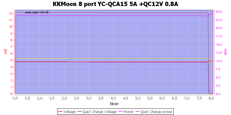
With Quick Charge at 0.8A it lasted 8 minutes. I do not really see any reason to test QC with less than 0.8A.
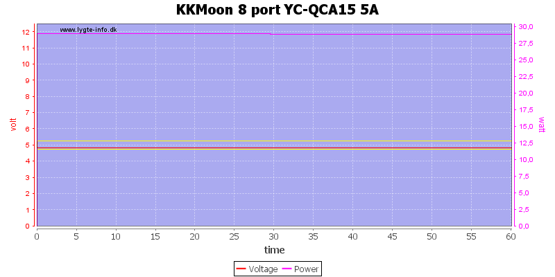
Running all the normal usb outputs with a total of 5A did work for 1 hour.
The temperature photos below are taken between 30 minutes and 60 minutes into the one hour test.
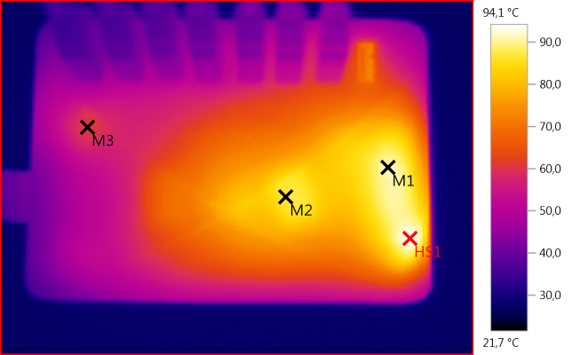
M1: 91,2°C, M2: 86,9°C, M3: 60,6°C, HS1: 94,1°C
Something is getting real hot here (HS1). M2 must be the transformer.
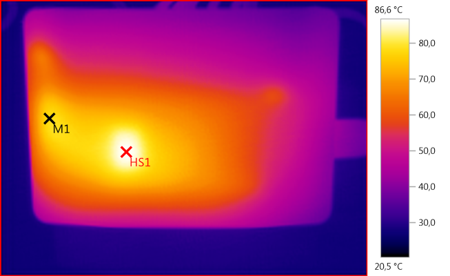
M1: 78,1°C, HS1: 86,6°C
HS1 is the transformer.
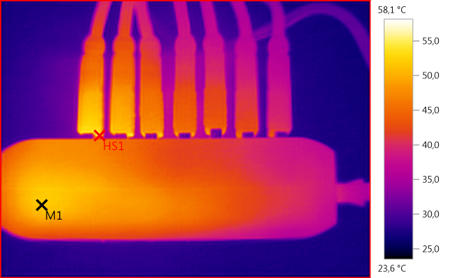
M1: 51,7°C, HS1: 58,1°C
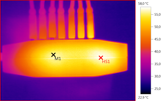
M1: 55,7°C, HS1: 58,0°C
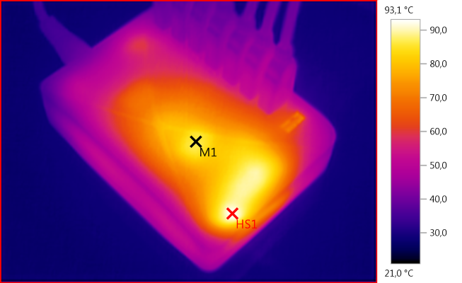
M1: 86,4°C, HS1: 93,1°C
HS1 is the rectifier diode.
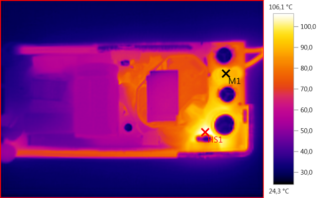
M1: 90,1°C, HS1: 106,1°C
After 5 minutes at 7A it is obvious that the rectifier diode is a major heat source. At these power levels there is usual used more than one diode or, even better, synchronous rectification.
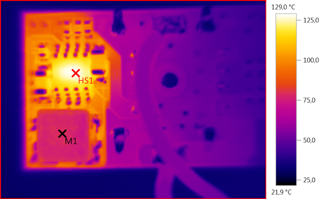
M1: 79,0°C, HS1: 129,0°C
A look at the QC chip after 1 minute with 1.5A at 12V, it is heating up way to fast.
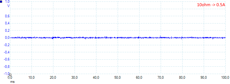
Noise at 0.5A load is: 6mV rms and 146mVpp.
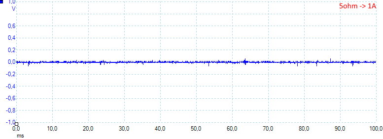
Noise at 1A load is: 7mV rms and 149mVpp.
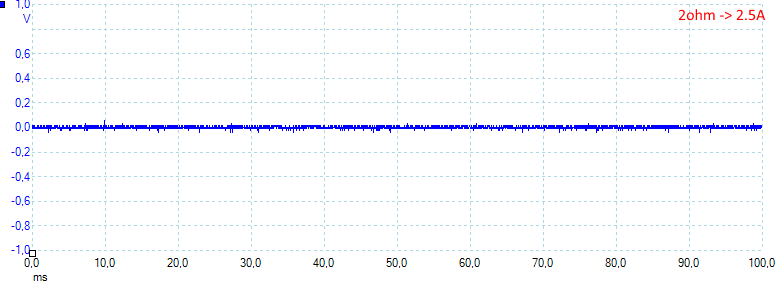
Noise at 2.5A load is: 8mV rms and 130mVpp.
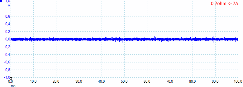
Noise at full load is: 25mV rms and 177mVpp. Generally the noise is low.
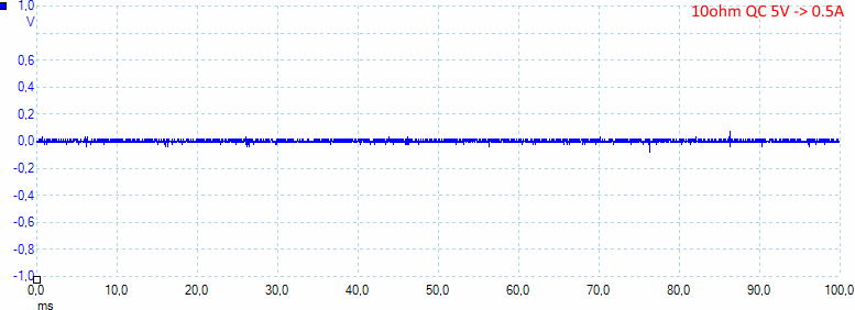
Noise at full load is: 58mV rms and 600mVpp.
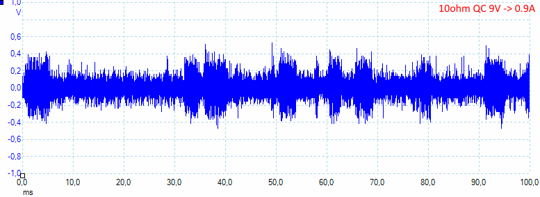
Noise at full load is: 190mV rms and 1200mVpp. That is not the case with QC, it is very noisy.
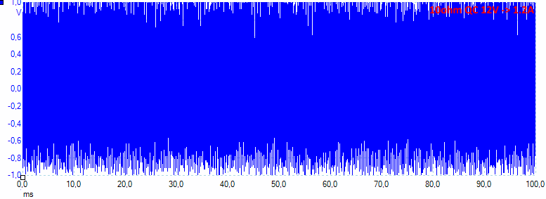
Noise at full load is: 660mV rms and 2770mVpp. Here it is totally hopeless.
Tear down
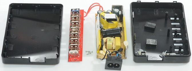
No glue or anything to open the box, the closing was with clips.
One circuit board is fasted with screws and the other with glued.
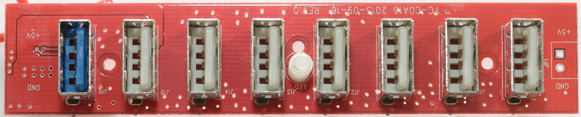
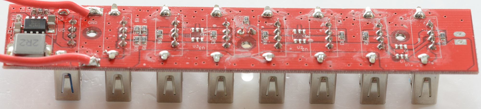
All usb connectors are on one circuit board.
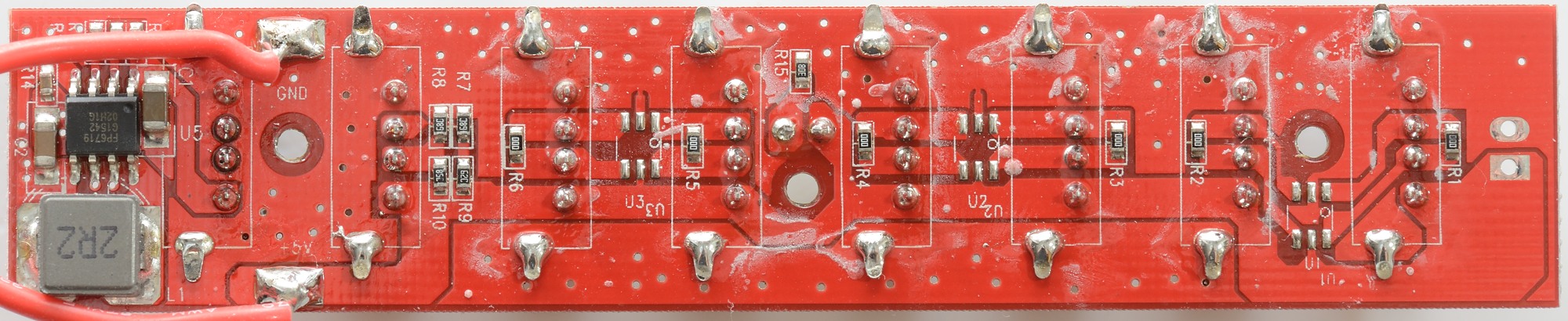
The quick charge circuit is a small IC and a inductor, here is also the reason it do not work. The chip need some cooling and obvious more output filtering.
There is one set of coding resistors, the circuit boards has space for auto coding chips but they are not mounted, instead the data pins is shorted to signal DCP.
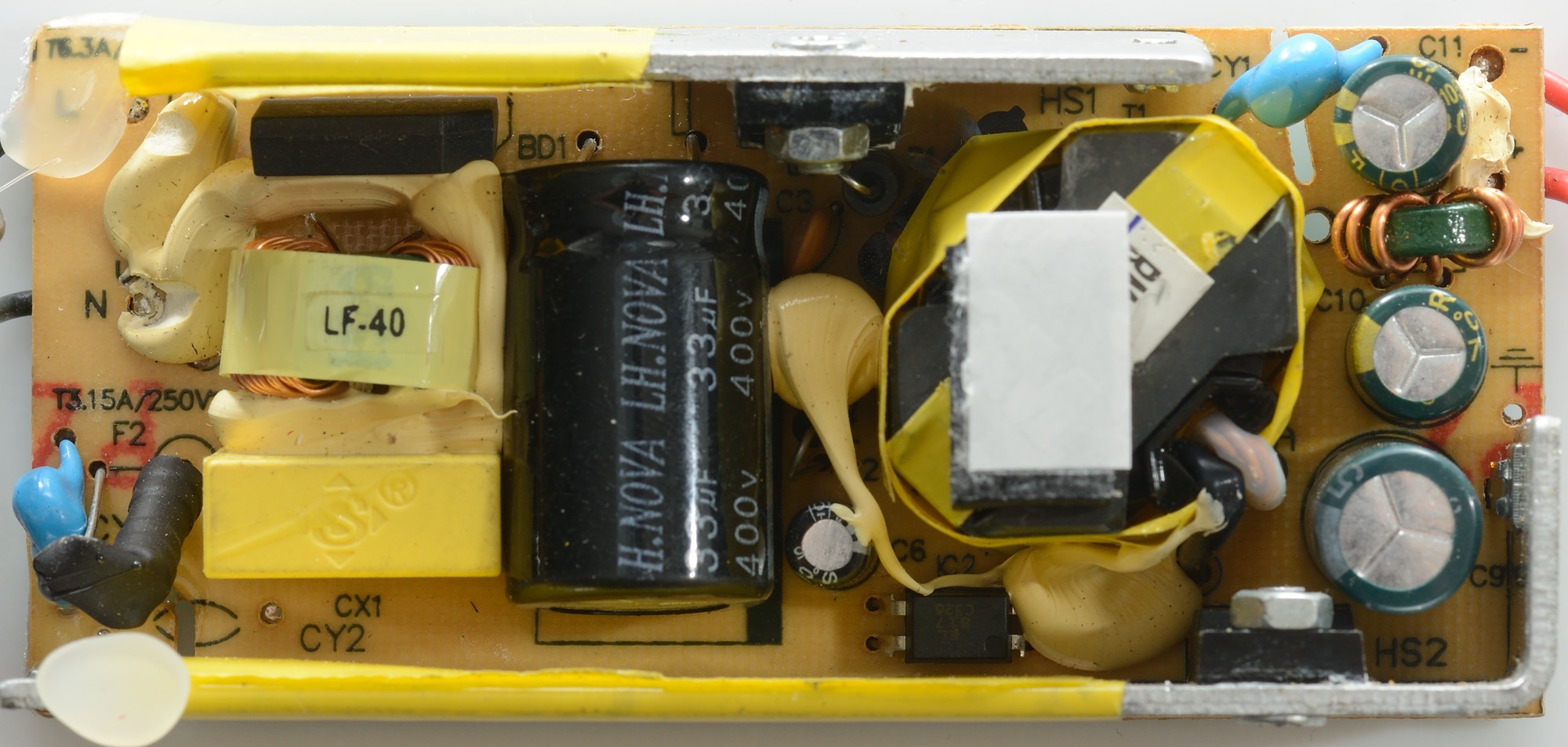
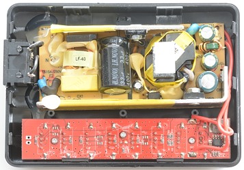
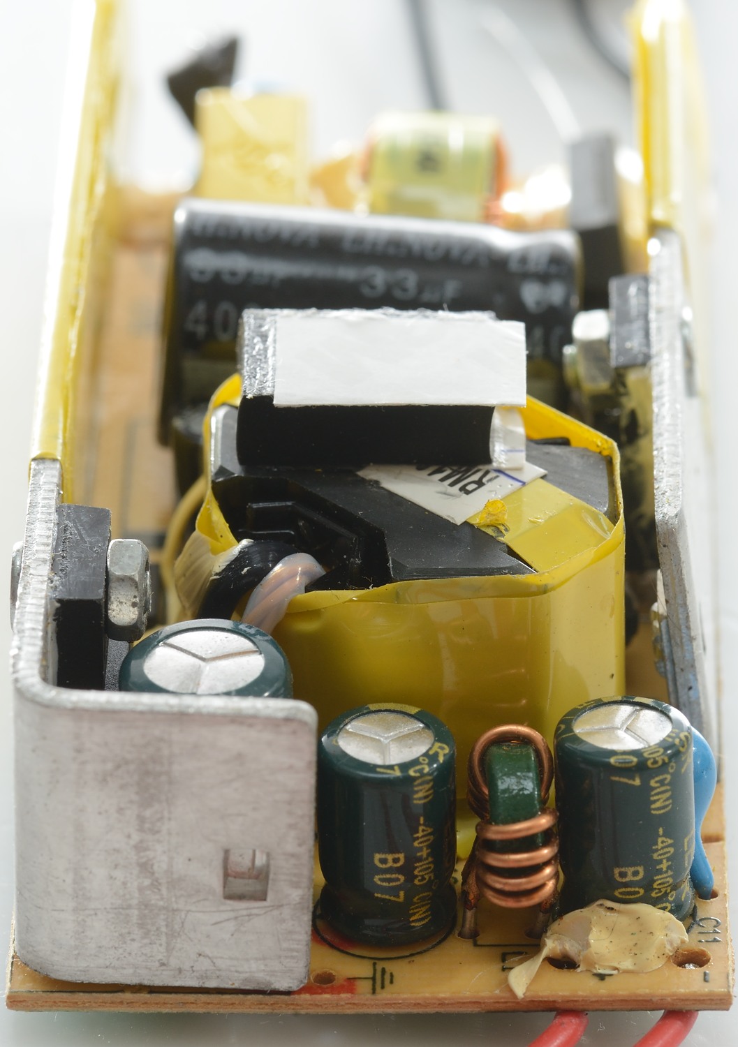
This looks like a regular 5 volt power supply with a fuse at the mains input, one common mode coil and a bridge rectifier.
The mains switcher transistor in mounted on one heatsink, the rectifier diode on the other. There is opto feedback and two safety capacitors. There is also a common mode coil on the output
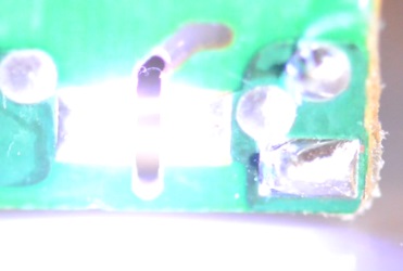
This is the rectifier diode heatsink and it has isolation tape where is passes the mains voltage section of the circuit board.
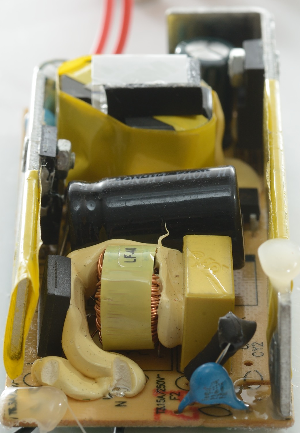
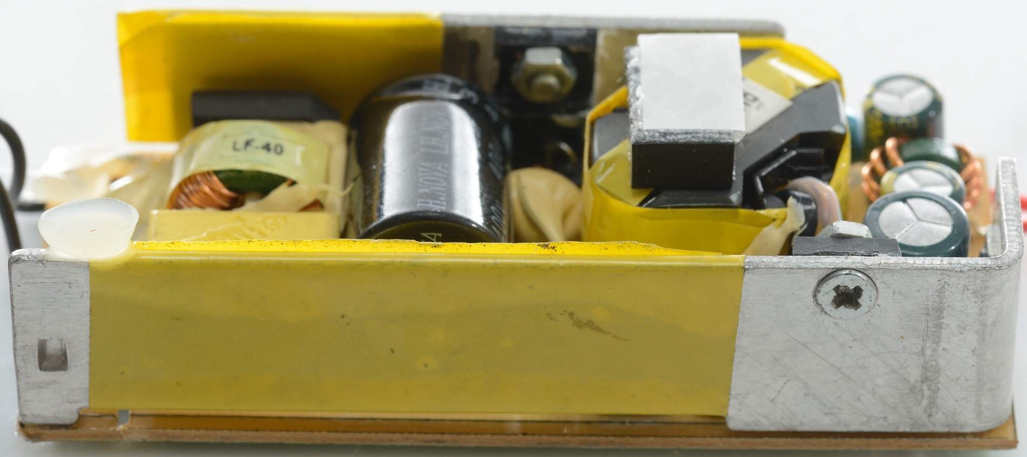
One of the safety capacitors with the fuse behind it. At the output the common mode coil can be seen.

The mains switcher transistor heatsink and the other safety capacitor.
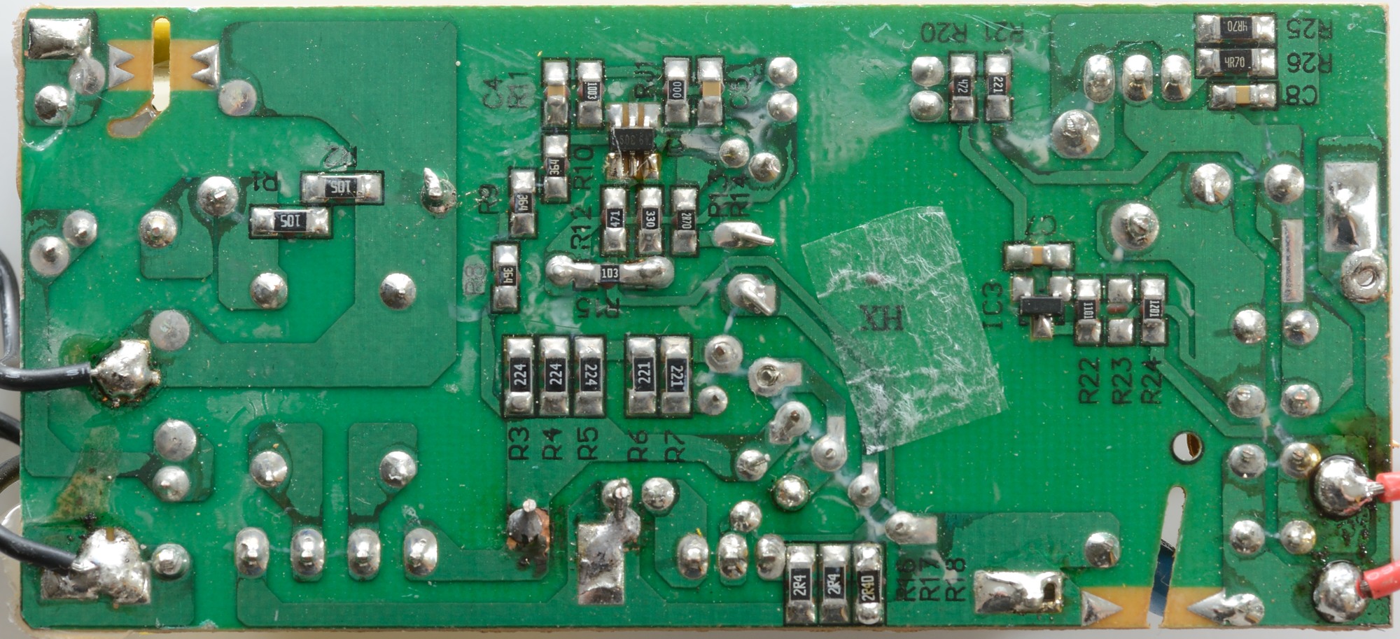
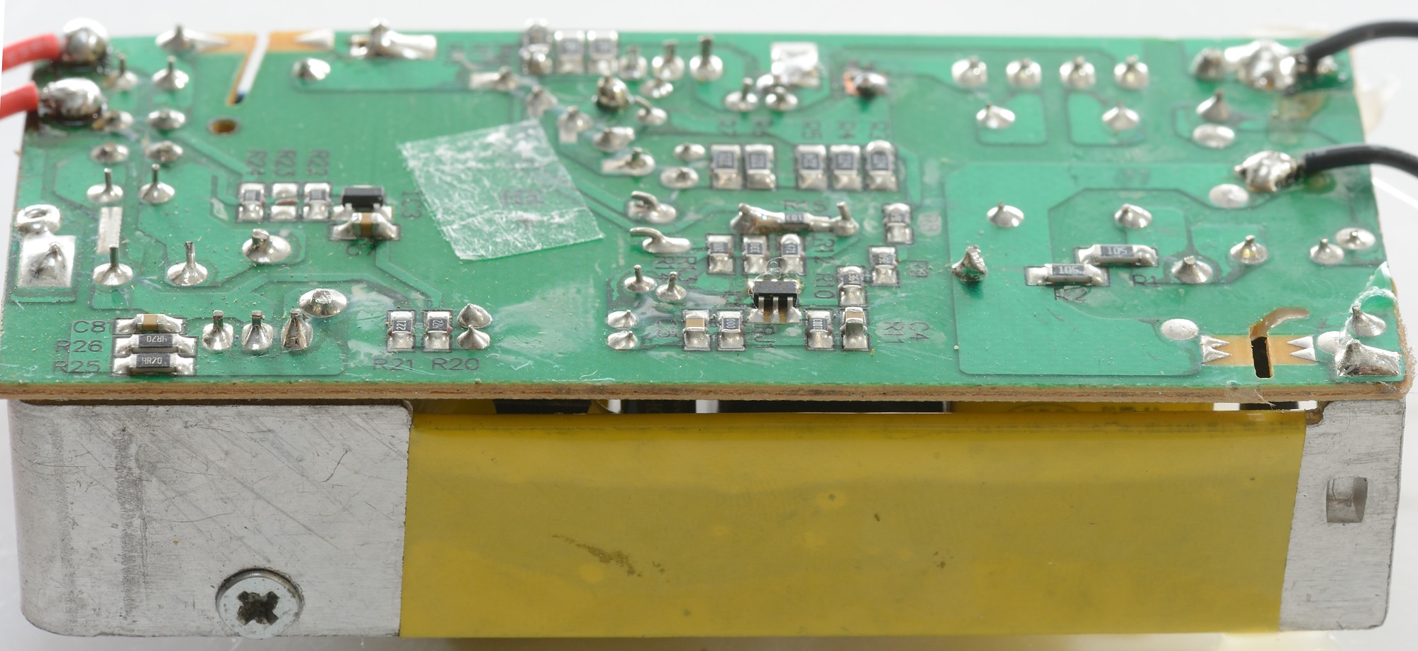
On this side there is the switcher controller IC (IC1) and the voltage regulator IC (IC3)
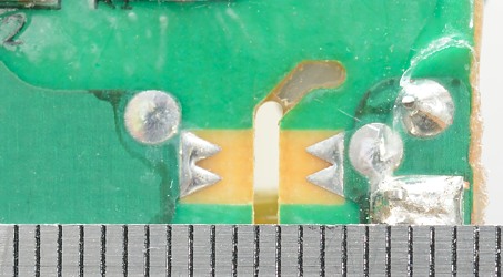
Safety distance is good, but the 5000 volt do jump over it. Because the 5000 volt is about 700 volt higher than required, I will not hold this against the power supply.
The charger passed the 2500 volt test, but failed the 5000 volt test
Conclusion
The usb power supply has a low noise and can deliver lot of power, but it gets hot and the coding of the usb outputs are not very good or even marked on the box. The quick charge output is useless.
It will work and can charge many devices at the same time, but do not expect it to charge fast.
As a ordinary multi output charger it is acceptable.
Notes
Index of all tested USB power supplies/chargers
Read more about how I test USB power supplies/charger