Bought off ebay, its my 1st regulated driver. Not sure if faulty or Im doing something wrong. Mode selection works, soldered the star for 2 modes and I have 2 modes, thats good.
Max current was about 2.8A on a XML2, close enough.
But apart from that, behaves like a DD.
Current drops with voltage like with DD drivers, and voltage is at 3.9v on a fresh 18650 (VTC4, capable of constant 12A draw like its nothing on another device), so its not the battery.
My understanding of a CC driver is that it varies the voltage to keep output constant if current is set.
I even saw 1A current when voltage dropped to about 3.85v, emitter voltage at that point was about 3V.
What exactly is wrong with it.
All measurements done on the output.
The regulation of the 7135 chip is by burning off excess voltage and feeding the led the voltage needed to obtain the set current (350mA per chip). For this to work you need an overvoltage to start with. once the voltage is lower than the voltage needed to feed 350mA, the chip does not regulate anymore, just sets the gate open and everything indeed is direct drive.
The 7135 chip is not able to boost voltage to get the desired current.
To get a nice regulated 2.8A, you need to make sure that the voltage from the battery, which is not that much higher than the voltage that the led works on at 2.8A, suffers no drops underway, which implies that you will have to remove resitances. Known resitances are in the springs (steel springs show about 0.15V drop at 3A, two springs=0.3V), the electrical contact between switch and body, and in thin wires from driver to led.
What also helps is using a battery suitable for high drain, under load they maintain a higher voltage, so more playroom for the regulator chips.
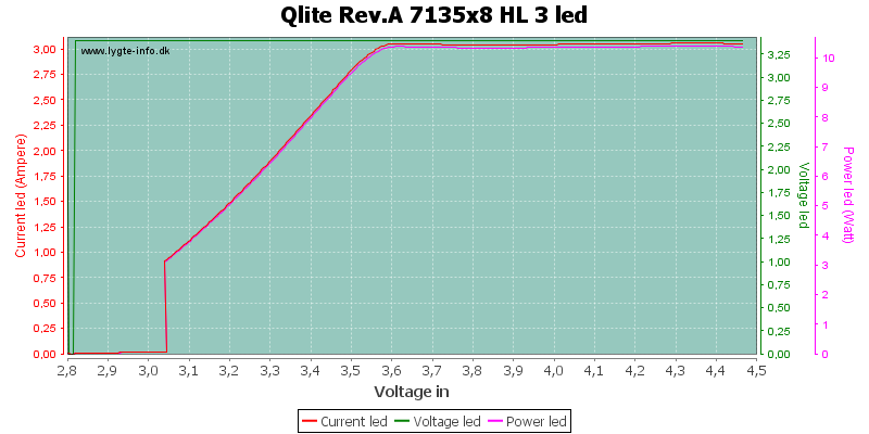
It should maintain 3v to the emitter all the way from 4v to 3v, while current stays at 3A all the way down to 3.6v, only after that it goes out of regulation and start dropping the current. So that means if I turn it on at 4.1 or 3.8v battery voltage, I should get 3v@3A at the emitter, which is supposed to stay the same to 3.6v battery voltage. Instead im getting 3.9v to the emitter on a fresh battery, which shouldnt happen, and current 2.8A which drops with voltage (also shouldnt happen). The battery is a Sony VTC4 and is able to supply 12A in another device without getting warm. Its not the battery then. Measurement done on the bench with direct soldered wires to battery tabs so no springs involved, using copper wires of 20AWG. Nothing gets hot (except for the led of course). I can clearly hear the pwm frequency of the driver on high, so its regulating and clearly not direct drive, but behaves like one and not sure what exactly it regulates. Theres no rookie mistakes in the wiring, I can also do SMD soldering so its not the soldering. Resistance problems certainly wouldnt cause the voltage to shoot up from whats expected.
If thats true thats the problem, the 7135 cant add extra voltage to what is coming from battery
You may go with 2 18350 or extension tube for 2 18650
Or
you need an input 3-4.2V Boost driver generating a higher voltage for an LED so you get the nessesary voltage overhead for regulation
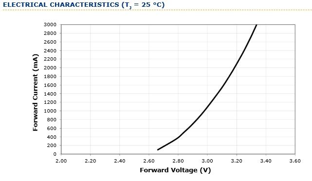
XM-L2 driven at 3A has Vf much higher than 3V, specially the newer batches. But 3.9V Vf @ 2.8A sounds very unlikely, not sure whats wrong.
In a 7135 driver when the current drops is either because the input voltage is insufficient or it has a programmed step down. As Djozz said a 7135 driver simply blocks the overhead voltage to limit the current, there is no conversion of any kind.
I did not understand correctly from the OP that you did not measure your voltages in an actual flashlight but controlled on your bench, that is why you got the answer I gave.
So then, I do not know what is wrong, only I know that the first version of the Qlite (a version of the 8x7135 driver sold by intl-outdoor.com) also showed PWM on the highest setting so it did not reach the specified 3.05A. They later adjusted the firmware to solve that. Perhaps your driver has faulty firmware too.
Doesnt need to, the battery supplies 4.1v fully charged. Thats when the led gets 3.9v. Led voltage will drop with battery voltage. I do have the neccesary overhead voltage. The tests done at lygte-info.dk have all been done with 1x 18650, and im using the same thing.
Its allright bud, I shouldve mentioned. The flashlight is being built (in parralel with one for a XHP70 and another one for 3x 5W 365nm UV, too many projects at once) so I can only play with the electrics on their own.
What is valuable info is that only the early versions of this driver had pwm on high, I did not know that and assumed theyre all the same. In that case its problem solved, obviously I got one of the crappy 8x7135 drivers and not worth investigating further. For what they cost, will keep this for spares and will order another one from a more reputable seller.
most 365nm UV emitters need 3.8-5V to get to its rated current
a typical 5W high quality emitter radiates 1000-1500mW
I also helps a lot getting the springs bypassed and use thick wires
if you overdrive em much thats not a good idea
I ordered from djozz the special board for my 3W Nichia NCSU276A
this one is in a convoy Host, but it is overdriving the LED, so a better colling board helps
Yes indeed the UVs have a driver that puts out 3.8v but only 1A. Will have to mod it for more current, the leds will be paralelled on a noctigon star. Will use it for photography, but not to lit the subject, theyll point at the lens instead. Have an anamorphic lens for my camera that makes some killer horizontal flares (like in the movies). With uv looks insane, just a little dim. Hence the 3 on a star…
Just a hobby nothing professional, otherwise I wouldnt diy it.
Yeah, those pesky UV LEDs would do better on 3x alkaline or 4x NiMH or indeed a boost driver, but it shouldn’t boost above 3.77 Volts input.
Maybe best to use 1xAA with a boost driver actually…
(but which one?)
Sure, but you don’t want to boost when the battery is more than 3.77 Volts.
And i thought the Nichia is advised not to draw more than 700mA, but i think the Jet 1 MK and MI7 push more Amperes than that on Alkaleaks or NiMH