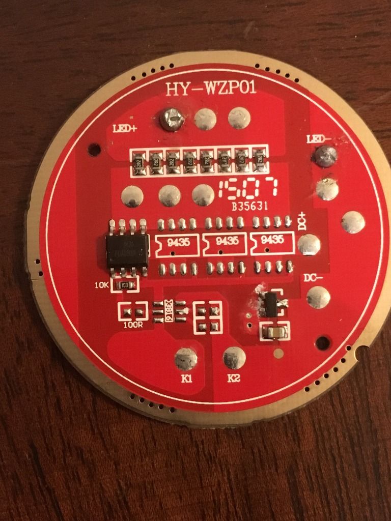
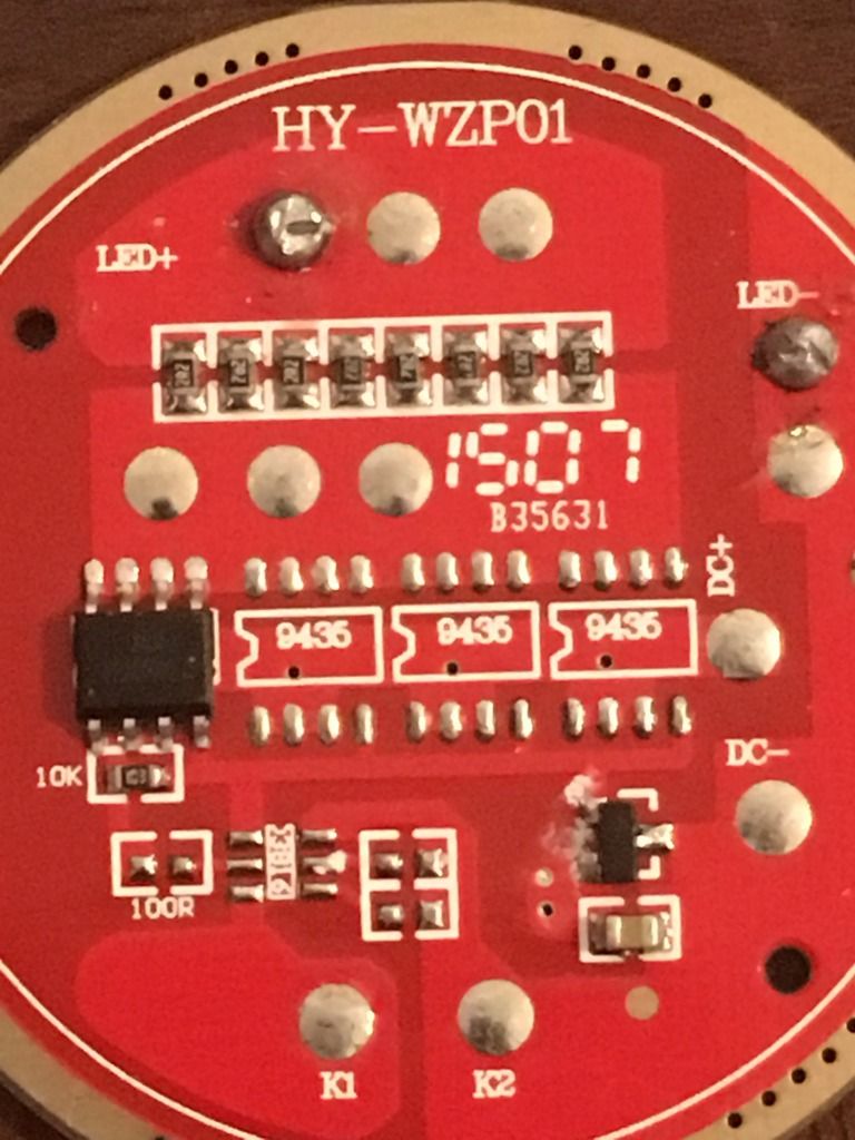
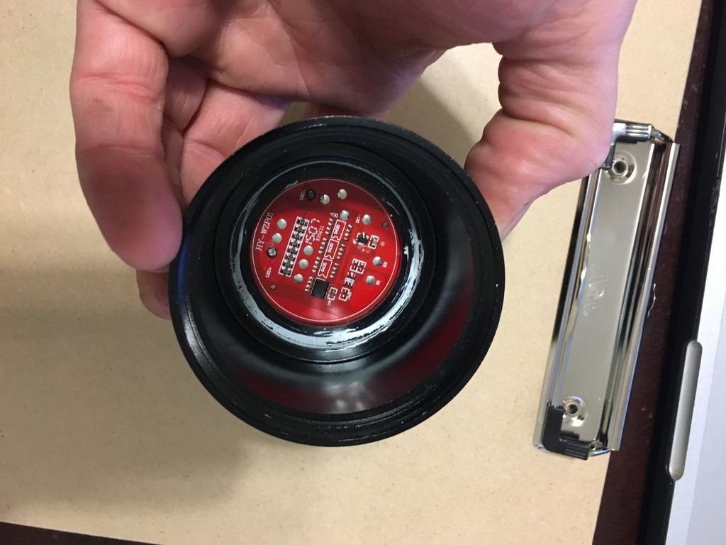
Hi everybody, I purchased this SME brand 4x18650 single emitter light from fastech "here": https://www.fasttech.com/p/4335100 And I have to say, the construction of the light if pretty darn good for the price, but the stock performance is lacking. Its basically a copy of the UltraFire JS-8054. My two main gripes are: the output is obviously lower than it should be, and the space between the 46mm driver and the aluminum shelf is very small. There's no way an inductor or anything would fit in between them, so I'm going to keep the light as 4p 18650's for a nice long run time for practical use. The driver it comes with unfortunately is not the 7135 based driver that I've seen in some other threads with clone lights of this type. It does however have a lot of resistors and some empty spaces for bridging or adding resistors. I don't know how to interpret this thing, can anyone offer a suggestion on how to mod the driver since finding a replacement 46mm driver is pretty tough? Even If I spend the ~$20 on a quality 46mm driver from mtnelectronics, I fear that it wont fit in the light due to the odd spacing of the driver and emitter shelf, plus with replacing the emitter and running quality batteries in this thing I'd like to keep it as budget as possible. I don't remember the exact number, but the stock output on high was something in the range of 1.2A-1.5A with a fake looking XML in very cool white. It will be replaced with an XP-L hi on a noctigon shortly. Anyway, here are the pics of the stock driver:
I'll take any increase in output I can get that won't fry the Xp-l Hi if I'm running 4x 25r's in parallel. Any ideas on ways to accomplish this by modding the existing driver? Thank you!
Edit: to make this thread searchable in the future, the official name/model of the light is : SME-T628
Just as a reference, here’s a slightly similar driver thread. The battery side of my driver looks identical, but I don’t have the option of simply just adding 7135’s or I would. 46mm driver ultrafire
The MtnE SRK drivers both 7135 and FET would fit, the tallest components are no taller than the mcu. Get the parts kit and pcb for ~$8 for either one. In that host I’d go for the FET version, fewer parts, forget that and stick with the current controlled 7135 version with maybe 5A worth of 7135’s(14-15 depending on 350 or 380’s) FET comes too close to the ceiling with 4P cells.
Thanks Rufusbduck, What exactly do you mean by doubling up on the resistors? Add the same value resistor stacked on top of the 8 ones at the top? Or could I remove all 8 and replace them with single resistors with double the resistance? Im a total noob
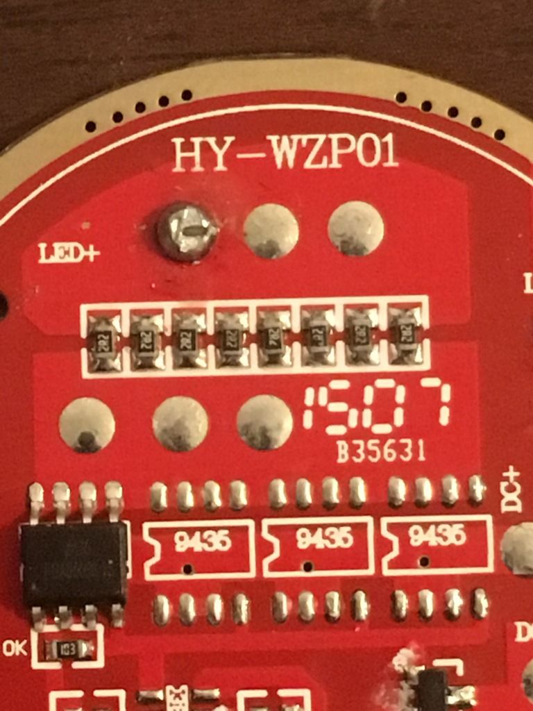
What he means is to add new resistors over the top of those. If they are the same value, then your current “may” double, if the MOSFET can handle it. The other option, is to solder your LED+ lead to one of the pads below the bank of resistors. That would have the result of eliminating the resistor bank from the circuit completely. I don’t know if you can see that there is a large “trace” just above the MOSFET, then a gap bridged by the resistors to another large “trace”. There are pads with solder already on the “traces” both above and below the bank. Your LED+ lead was attached above, or “after” the resistors.
I see, thanks for the insight. In theory, if I soldered the LED+ to pad below the resistors as you suggest, would this be direct drive? Im willing to try, if I somehow blow the board then I’ll just order another with the 7135’s. I just don’t want to fry anything else that can’t be as easily replaced, but I’ll try out all my experimenting with the cheapo LED the light came with just incase.
If the answer is yes to the direct drive question, would it be best to use a protected cell vs a 25R to avoid the direct drive being too much for the emitter and/or board to handle? Thanks!
Go and goggle “yn-20-5” here. I did a “breakdown” of that and the –3 version.
That row of resistors are all parallelled together to act as a ballast resistor.
The 9435 is a 30V FET, which is switched on/off for PWMing the LED.
That little 3-pin doodad is the µC itself! The cap next to it (brown rectangular thingy next to it) holds up its power long enough to sense mode-changes.
So yeah, you can parallel some more resistors across them, or just short them for direct-drive (for the 5-10sec the poor LED would last, haha). Just need to short one of them, and the bulk of the current will go through that bridge.
…or just connect the LED+ lead to one of the solder pads below the bank of resistors. Yes, that does (also) make it direct drive. As Lightbringer says, the LED may not last long, especially if you have multiple cells in parallel pushing power through that FET.
Edit: Then again, if you happen to have a Luminus SBT-70, or other such high-current ~3V emitter lying around, you could put it in there.
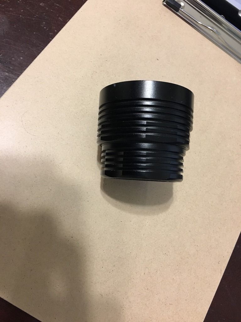
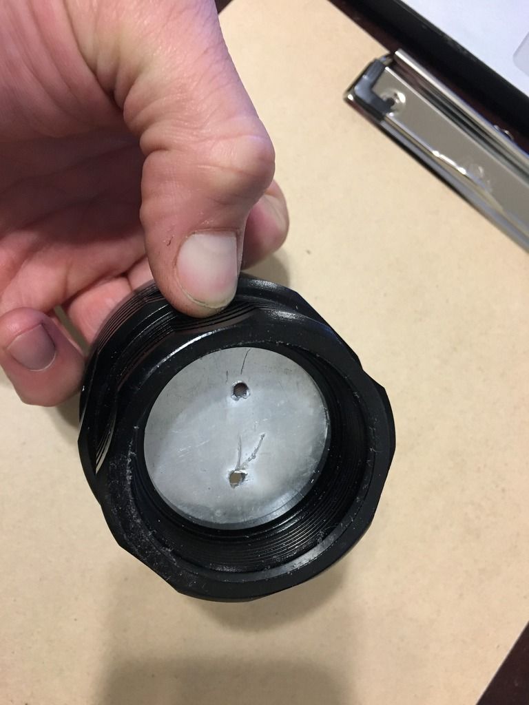
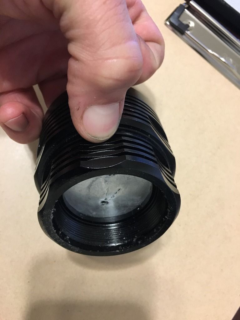
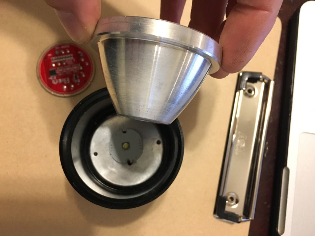
Thanks for all the input guys! I’ll snap a pic later if I’m able to get one to come out well so that it’s useful, but the gap between the led plate and the driver shelf is minimal. I’m measuring between 2mm and 3mm with a handheld tape measure, but its probably closer to 2mm.
I’m probably going to try the suggested mods above and hope it creates direct drive that won’t blow up right away but if it does, then the 46mm SRK 7135 based driver from mountain will probably wind up in this light.
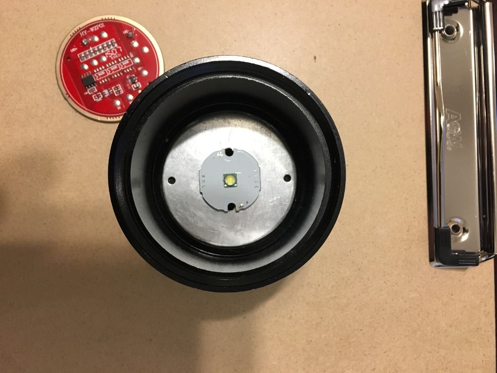
The good thing is since the led plate is so large ~50mm diameter, I can order one of the large 30+mm MCPCB’s from mountain, put an xp-l hi on it, and really drive it hard if I can figure out a way to bolster the thermal path from the plate to the light itself. Pics to come, thanks again.
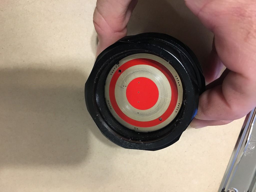
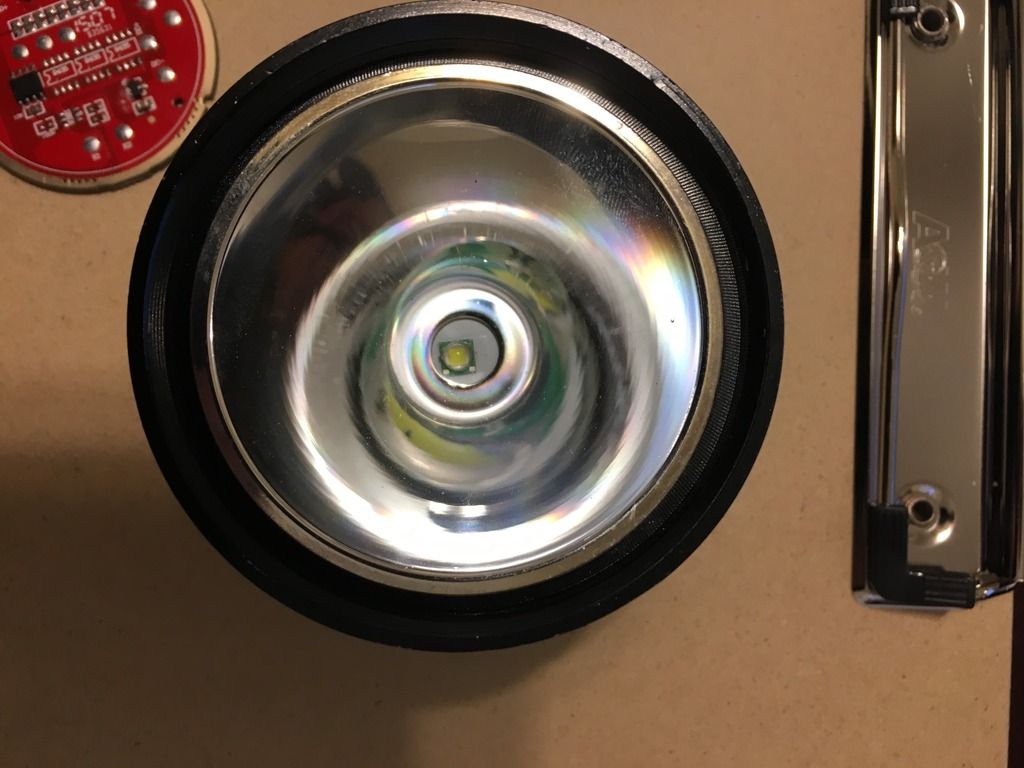
Ok here are some pics of the head of the light. If nothing else, maybe this thread will give some info for future mods or decisions on which light to buy. It's a shame that its relatively difficult to mod this light for series cells. I know its been done, but its waaaaaay above my skill level, so I'll stick with an xp-l hi and enjoy the longer run time of 4 parallel cells.
Also, I suck with computers in general. I added captions to each of the photos for a little explanation, not that its really necessary, in the "image description" portion of the add image box, and none of them are showing up in my post. Any ideas why? or is that normal?
Is adding resistance to the bank the same as doubling the resistors, like someone suggested earlier? How is this different from removing a resistor and shorting it by connecting the two points with solder or a small bit of wire? Thanks for educating a noob
Thanks so much for the education!
If I have some resistors that are similar in shape to those on the board but don’t have the same value (I might harvest some from a broken macbook magsafe charger), would they work? Do the resistors added in parallel over the top have to be the same value, or can they be different values? Starting with your calculations above, is there a way for me to calculate/estimate the increase in current? Does V=IR work for estimating the current in this way? Many thanks
On that same note, I do have a small pile of 5 or so drivers that I’ve somehow partially rendered inoperable while trying to mod some lights. Mostly Njang/qlite 7135 based drivers but also a buck driver or two. Would harvesting the fet from any of these and adding it to or replacing it in one of the labeled “9435” spots on the board provide and theoretical benefit?
I’d be very careful, and if anything, do this in steps vs going whole-hog and frying the LED.
Those are “2R2” resistors in the pic? So divided by 8, that’s 2.2Ω / 8 = 0.275Ω.
That’s just a ballast resistor, and how much current goes through the LED depends on the cell voltage and Vf of the LED.
I’d maybe try parallelling a 1Ω resistor (“1R0”) at a time, and measuring the current with a fresh cell each time (when current would be maximum).
And even that’s pushing it, because that resistor would be hogging a proportional amount of current (ie, more than twice what any of the other 2.2Ω resistors do).
Safer would be just stacking more 2R2s one or a few at a time.
Yeah, frying it would be a “learning experience”, but…
They use 8 to divide the current and heat among them. One stacked pair will pass more current than any one of the others so more heat will be produced by that pair in that spot. Each additional stacked pair will further reduce resistance. Resistors have power ratings which if exceeded will cause them to burn out. Generally we can get away with upping the current with “resistor mods” but at some point something gives. Heat has the added consequence of reducing power ratings so the harder you push things the more likely they are to fail at an accelerated rate. If you’re like some of us you will keep adding resistors until you find you added one to many. while others with a more restrained disposition will try only a few. Not being an electronic engineer and having only the rudiments and experience to cling to I’m guessing that this particular board will fall short of any hot toe expectations so personally I’d just go ahead and order an SRK driver(in fact that’s what I did for my SRK and as soon as I can crack it open it will get the treatment. For a single led fed by 4 cells I’d still recommend the 7135 version(available in kit form only right now) to control current through the led to match whatever heat sinking improvements you manage. If you can’t build it yourself either wait for Rich to list more or ask for aid in getting one built.
While hardly ideal (resistance of metal goes up with temperature, whereas carbon more or less stays the same), standard 30ga wire-wrap wire has a resistance of 0.339Ω/1m ( AWG American Wire Gauge Diameter and Resistance ).
If you want to try a 0.1Ω resistance, that’d be (0.10Ω/Xm) = (0.339Ω/1m), X = 0.295m or roughly 1ft.
So coil 1’ of wire-wrap wire into a loop (inductance shouldn’t be an issue) and that’s your cheapie resistor that can handle some decent amperage.
The lower the resistance, the less wire needed. The more resistance, the more wire needed.
Oh, and I’d use that instead of the parallelled resistors, not parallelled with them.