The driver is from an Astrolux S3.
The question i have is if i can replace the FET with a bunch of 7135s.
I want to replace the FET with 19x 7135. (sorry, i just don’t like unregulated DD)
My specific question is if the Atmel chip can power them with leg #6, like it powers the single 7135 with leg #5.
[EDIT]
CHanged the title, reading on will clarify.
[/EDIT]
19 of those chips in a tower like build? you serious m8 ?
Do you actualy know that they have int throttling mech when they overheat? And in your case they will in a matter of a minute, not to say seconds
Why dont you just buy a 105c and mod it ? Ways more easy do do/craft though
“My specific question is if the Atmel chip can power them with leg #6” yes it can, yet i aint use if its possible/reliable enought to do so with 19 of those
Those early MNT SRK 46mm drivers had many issues with all those 7135s
Its a waste of time m8, just build a 16x chipped 105c and enjoy the throttling
Yet, i aint sure why to do need those in a S3 host? I would use max 2 amps in there, its supposed to be a functional edc of some sort( those Eagletac 14500s are like 1000mah)
Done that. S2+ KD 219C triple build and questions
16x 7135 is not a lot for a triple though…
But 19x 7135 is only 1 Ampere more, hardly noticeable difference.
But 6.65 Amperes : 3 LEDs = 2.21 Ampere per LED, which is perfect for Nichia 219C.
And with the 1x 7135 for low modes it can last very long on this driver.
Astrolux S3 is a 14500 mini Eagle eye X6, it comes with a FET+1 driver on a XP-L HI.
Plan was to limit the current to around 5 Amperes = 14x 7135, but 12 is okay too.
The donut is made of copper sheet and the 7135 chips are soldered to it for thermal (and electrical) path.
Fits quite snugly in most pills, with some thermal paste it should be better than stacked 105c.
The idea is to optimize the electrical path with bypassed springs and a fat switch so the light can run 6.65 Amperes on a VTC5 (my high drain / low sag cells) until the battery runs too low to maintain it.
With modern low Vf LEDs this should work quite well, especially when you have 3 in parallel running a modest 2.2 Amperes each.
With a FET DD driver an optimized electrical path would cause the current to be too high to be reasonable / useful / efficient / nice for both battery and LEDs (i.m.o. because i like LEDs to do 100 Lumen per Watt or more).
With a FET DD driver you need some losses in the springs etc. to keep the current within (personally preferred) limits, but this means it’ll only be very bright with a freshly charged cell, and that’s why i’m not a fan of FET DD drivers.
I bought a reel cutting with 100x genuine “PD” brand 7135s for just under $10 from Fasttech. (i read they’re good ones) https://www.fasttech.com/product/1124300
So there’s less than $2 worth of those in here.
It can work but you have to watch the temp when soldering to a lot of copper, they can be killed and identifying a faulty chip in there let alone fixing it/them won’t be easy. I’d suggest a current test before adding it to the mcu board.
Edit: Serious mistake made; I’m not able to read graphs. I was reading the voltage from lumen output. Everything below is one big boo boo
Hey Jerommel how are you doing?
I’m not familiar at all with drivers and stuff, but I nevertheless want to share my idea which could simply be flawed. So you want regulated current, so that’s why you want to replace the FET with 19x7135, meaning 19x350mA = 6.65A.
I believe this is not going to happen.
The boundary condition for this to work is that the available voltage (from the cell) must be higher than the required voltage to obtain the total 6.65A.
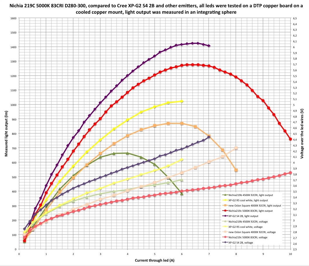
You said you have three leds parallel, meaning 2.2A per led. I don’t know which led you will be using, but for example let’s take 219C.
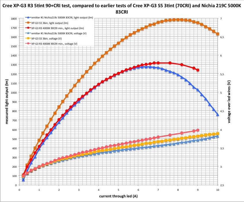
2.2A going through the led means a Vf of 4.3V (see graph). This is the required voltage under load. So a single 18650, no matter whether it’s high drain or not is not able to generate this Vf for the 2.2A per led. An XP-G3 requires a higher voltage to obtain the 2.2A. https://c3.staticflickr.com/9/8556/28583394506_42a052b0c2_o.jpg Not to mention that the available voltage from the cell will drop as a function of time (depleting cell).
This means that a 19x7135 driver in your case (single cell) will behave roughly like a FET driver I think.
Perhaps I’m not understanding something correctly?
(P.S. I think a lot of flashlight manufacturers use a so called “constant current” driver, and yet the output decreases as a function of time (with turbo), i.e. with depleting cell. The reason being that the boundary condition of sufficient available voltage is not met; it’s nevertheless a “constant current” driver.)
Actually the term “constant current” in this case means “current limiting”.
It can not exceed 6.65 Amperes like this, it can however be less than that.
I think you read the graphs wrong, 219C and XP-G3 have a Vf around 3.2 Volts @ 2.2 Amperes.
There will be some losses along the way from battery to LED, including the 0.2 Volts voltage drop of the 7135s (iirc).
So we need at least 3.4 Volts from the battery for 6.65 Amperes.
Probably (my guesstimate) we need at least 3.5 Volts from battery through contact points (battery to springs), switch and driver to the LEDs.
Fixing anything is impossible now… :person_facepalming:
I was careful with heating it up for soldering, i hope i was careful enough.
I’m waiting for stuff from China to be able to test it.
Clamp meter is on its way, and a S2+ host too.


