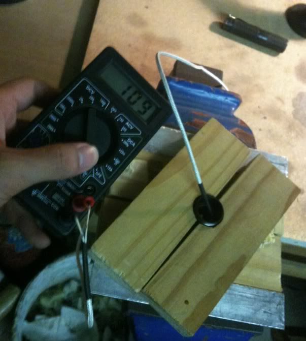
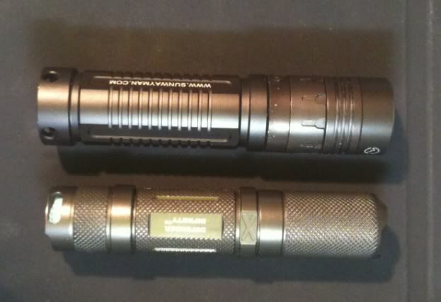
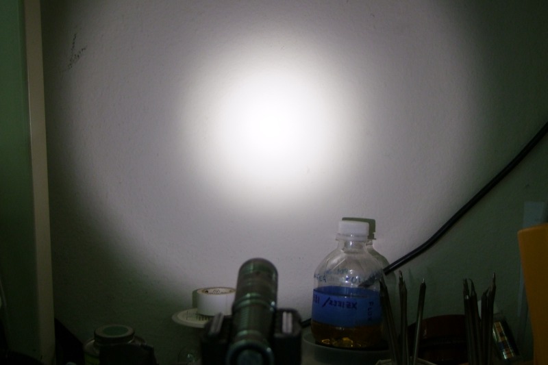
The V10R is one of those more name brand lights which definitely has with a very nice UI, and killer looks! but because I'm a neutral convert, it comes with a horrid cool white XP-G, and more often than not, some shade of green.
Such name brand lights are supposed to be aimed at not falling apart in the hands of most users, and this SWM V10R does very well on that part, with the head VERY firmly locked with Red locktite.... Couple that with a design that doesn't give you much to grip onto, and we have a very very very difficult torch to mod.
My first V10R, arrived from SWM directly, and one of the first things I tried to do was get to the emitter. With wooden blocks I carved slots into, and rubber bands, I struggled to get enough grip on the key parts, and I ended up crushing the threaded section of the head. Getting the battery tube to fit again required some emergency hammering, which caused a lot of the very thick anodising to chip off. Long story short, the results were less than aesthetic, but at least I got a neutral tint emitter into it....
So today was take 2, and SUCCESS! I managed to finally crack open the head of 2 more of my V10Rs without destroying them, infact, I didn't even put a scratch on them.
So anyway, heres the method, for the benefit of any other members who are feeling lucky about opening up their V10As from DD if they ever feel so inclined, or to scare people away from trying it....
[Mod Rating : Very Difficult with a high chance of Failure]
1) Identify that the head comprises 2 target areas - the Heatsink fins, and the threaded area. The bezel, and especially the ring should not be exposed to excessive forces as it will affect the feel of the ring afterwards.
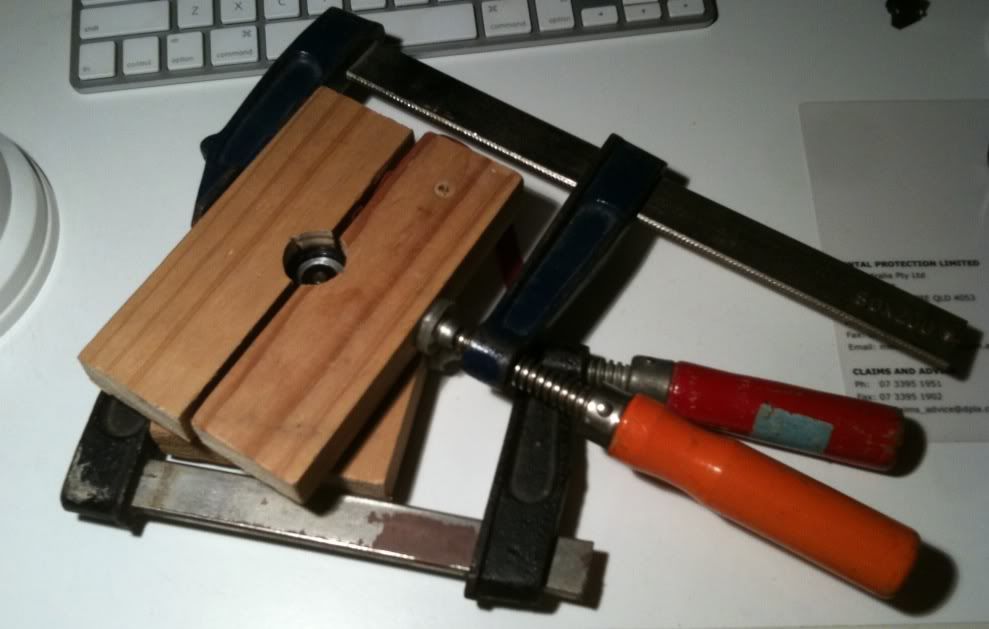
2) Cut 2 blocks of wood about 20mm (3/4") thick, probably 70x40mm (3x1.5") which will be used to clamp the 2 key parts of the head. I just had stuff laying around which I used
3) Cut holes into both blocks, about 1 mm (< 1/16?) larger than the diameter of the torch. Essentally allow space for a rubber band/leather strap to fit around the head. First time I filed out half circles into the wood but I wasn't accurate enough. This step needs to be performed Extremely carefully and accurately. I would recommend having this done on a drill, or a lathe, or spending some time carefully filing away, because any inaccuracy (more than 1/32) will result in the need for more compressive force, with increased chance of irreversibly bending the parts.
4) Split the blocks in half, cutting with a wider blade, or sanding the gap to 1-2mm each side to allow enough room for it to clamp down on the torch (and for the rubber bands) Splitting the blocks slightly off centre allows for a larger and a smaller half, which somewhat helps later on..
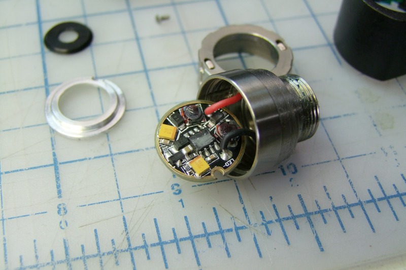
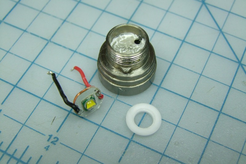
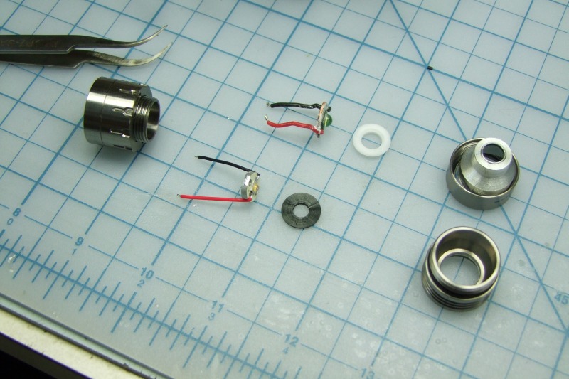
5) Remove the Driver from the head. Unscrew the single retaining screw, and with the parts out, unsolder the led wires from the driver.
6) Fabricate a filler block for the threaded section of the head. This is to prevent the crushing of the threads, which would otherwise be unsupported. I made mine from aluminium, but anything that is no softer than aluminium would suffice. The key here is achieving a very accurate almost press-fit. Any slop will end up allowing the threads to be crushed at the next stage.
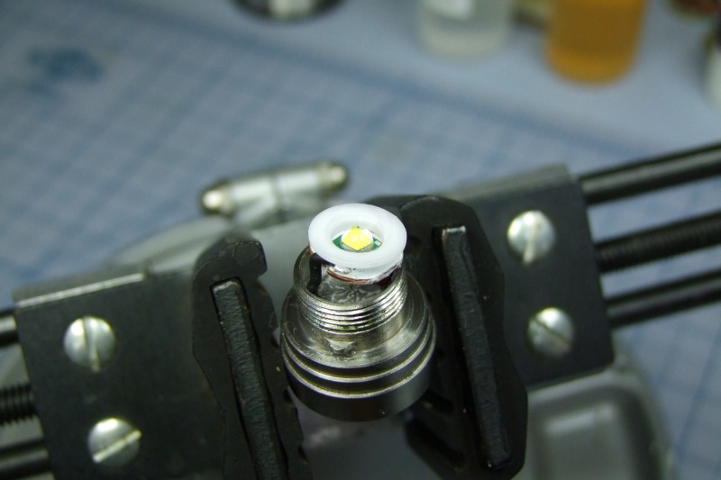
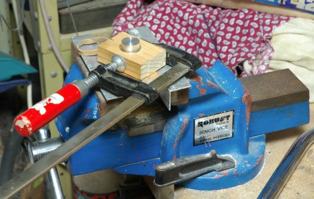
7) With some 5mm wide rubber bands, clamp the head of the torch in the first block, ensuring only the heatsink is being clamped. I used a vice because it was best able to maintain the blocks square on.
8) Once stabilised, insert the block into the back of the head, and then clamp the tail end of the head with a similar approach.
9) Without over tightening, Try to torque the 2 parts apart first. It will likely slip a little, so tighten either of the clamps little by little. Overclamping will increase the chances of irreversibly bending parts of the head, so try to minimise the risk.
10) The clamps may pop or slide out of position, or the rubber band will slip out while torquing, so be patient, and reposition if required. We want to try to use any compressive forces as effectively as possible, as any mis-directed force will likely end up destroying your light.
11) It should eventually crack and start to unwind, after which your effectively on the home stretch.
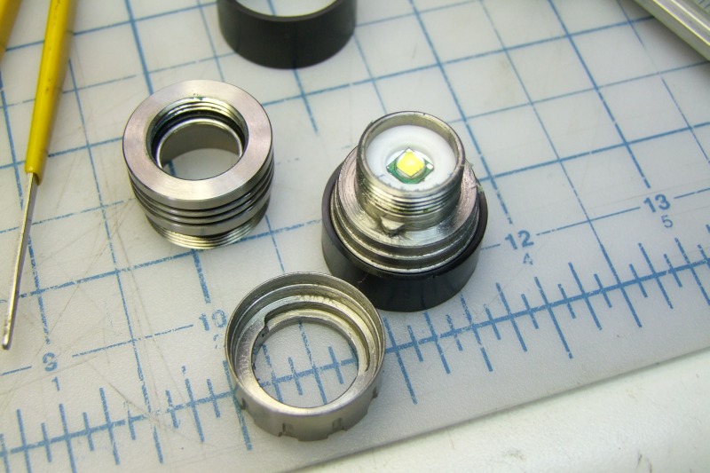
12) Clean up any excess locktite with a sharp probe or the end of some tweezers. I had a dental sickle probe that I use to clean out the threads. Be careful not to cut up the o-ring inside the heatsink half of the head while cleaning... (oops...  )
)
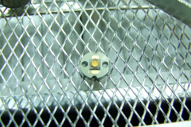
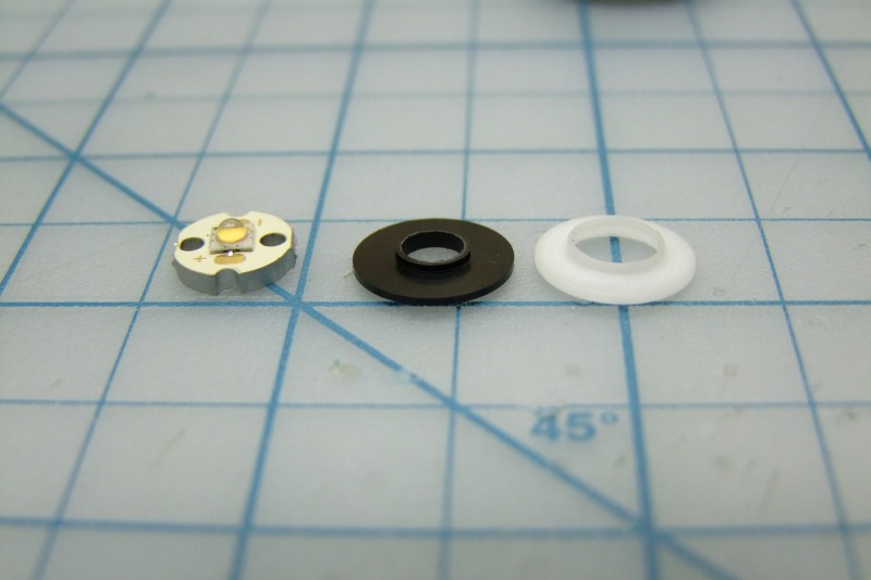
13) Yay, now its ready for emitter mods!
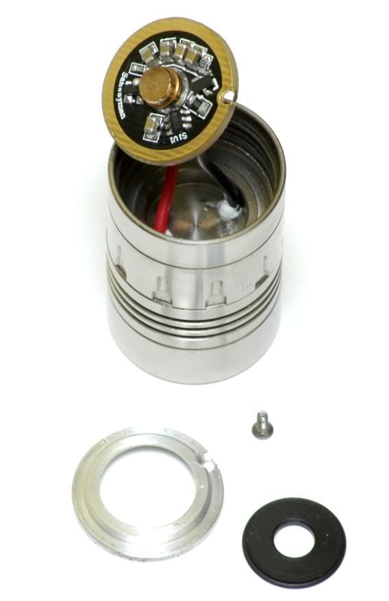
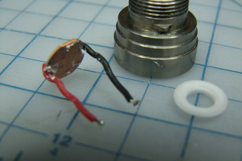
Unsolder this driver to provide more depth, and to allow you to apply heat to the inside if you want to try to soften up the locktite first. Be aware though that more than 60-80 degrees Centigrade will demagnetise your magnets, and make your light susceptible to external magnetic fields changing brightness. (imagine walking around on minimum, putting the light near your magnetic clipped wallet and it goes to max brightness)
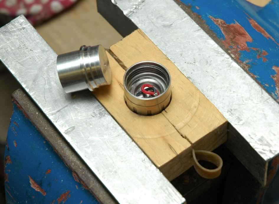
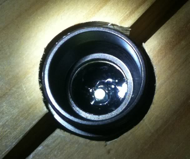
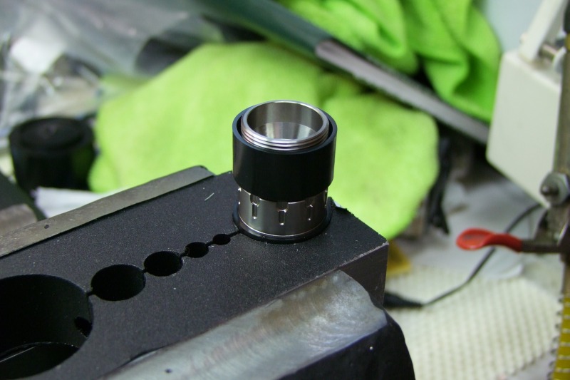
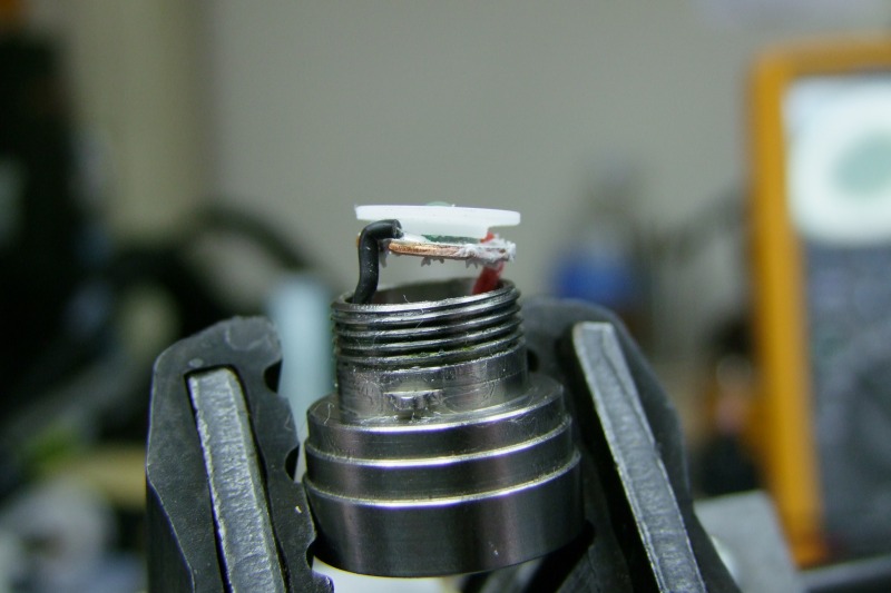
Head is now clamped, with the block. Rubber band is around the heatsink section only. Ring at this stage is still able to turn freely, a good sign of a well balanced and accurately positioned blocks/rubber band. Other thing is to try to have the rubber band centred to the block - it helps to keep the blocks more stable when trying to clamp together.
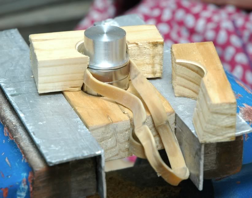
Clamping the back end of the head. Notice the block isn't quite split down the middle, which allows the larger one to sort of 'clip' onto the head of the torch by itself, which is quite convenient.
Ready for some torquing...
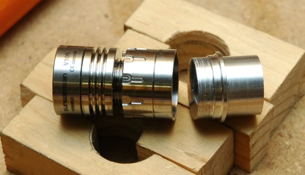
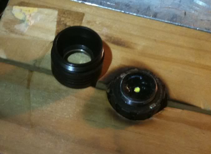
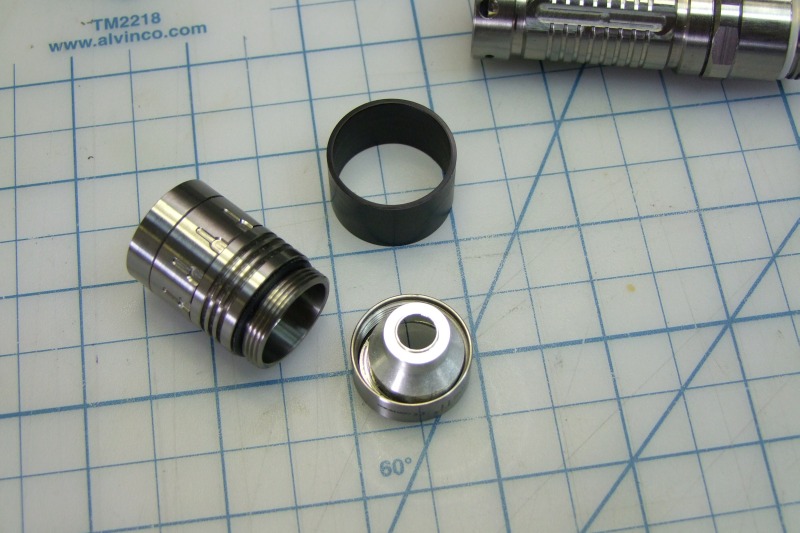
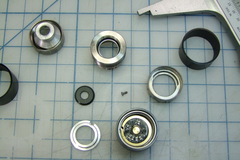
Parts Apart! - notice the wear against the aluminium.. Wouldn't recommend anything softer than aluminium after seeing that.
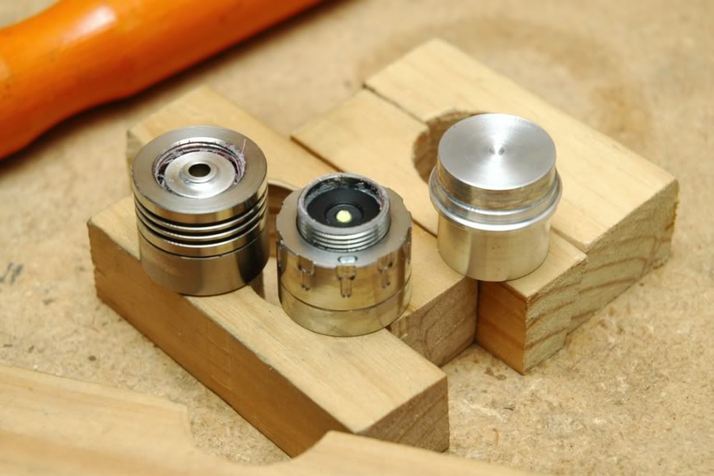
Lots of locktite crumbs! Try to leave the magnetic ring on the bottom half. This is to preserve the grease. I cannot find any grease of sufficiently high enough viscosity to restore that same feeling. Even the super thick stuff I have feels too light on the control ring, so best thing is to leave it alone.
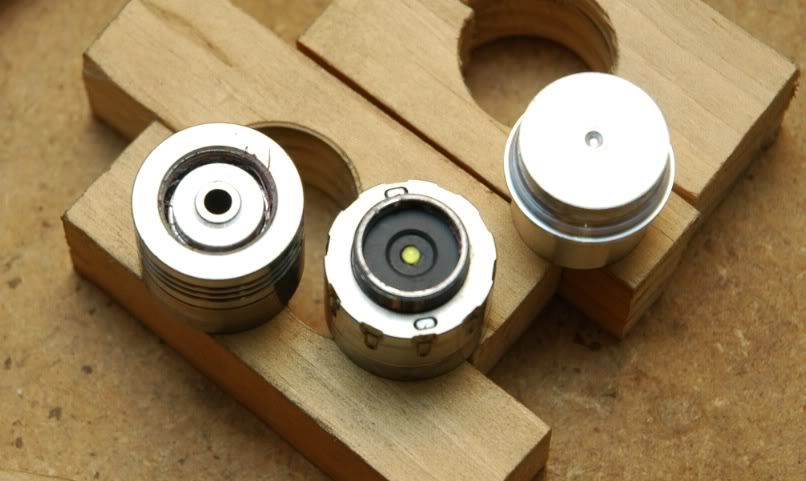
Also, don't lose those magnets... Polarity is important too. If one comes out, try to re-install it with a non-magnetic tweezer. Polarity is the same direction for both.
Ok, so I hope that this has helped people understand what their up against, and that it helps save someone from destroying their light. I've already learnt with my first one. At least it made it easier to use that light as I'm not as scared to scratch it ;)