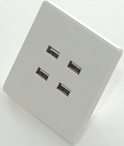
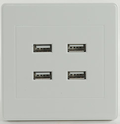
LEORY Wall outlet
Official specifications:
-
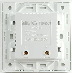
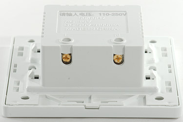
Input parameters: AC110-250V
-
USB output parameter: DC5.0V / 3100mA
-
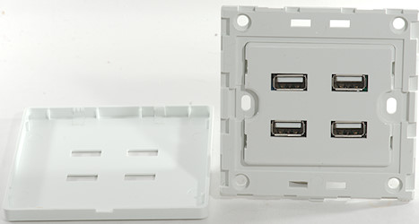
Size: 8.6cm*8.6cm*3.5cm
-
USB Ports Number: 4
It is from Aliexpress dealer: Audio&Video Professional Store
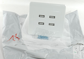
I got it in a envelope, it did not include any box or instruction sheets.
Measurements
-
Power consumption when idle is 0.15 watt
-
Top two usb connectors is coded as usb charger (DCP)
-
Bottom two usb connectors is codes as Apple 2.1A
-
All output are in parallel.
-
Weight: 80g
-
Earth is not connected to usb shield (It has no earth connection).
-
Need 25mm deep hole.
-
Extend 6.1mm out.
-
Frontplate: 85 x 85mm
-
Back: 53 x 64mm

The charger can deliver a bit over 4A on the output and when overloaded it do not cleanly turn off, but starts a cycle with off-on.
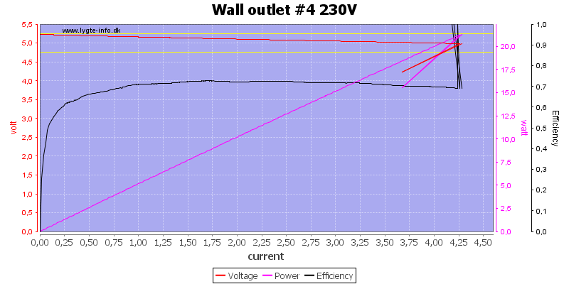
The other output is the same.
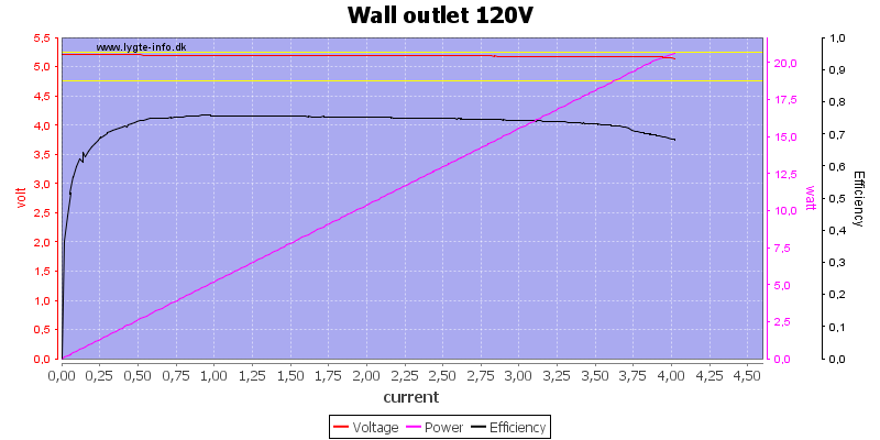
All output combines at 120VAC, the current is slightly lower at this voltage.
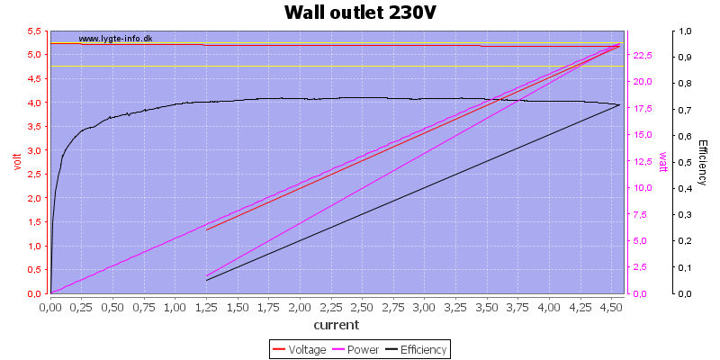
All outputs combined at 230VAC, there is no individual port protection.
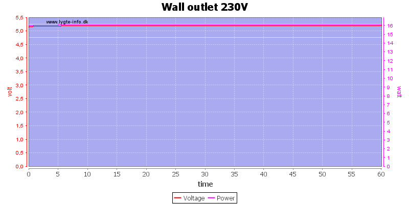
No problems running one hour at 3.1A.
The temperature photos below are taken between 30 minutes and 60 minutes into the one hour test.
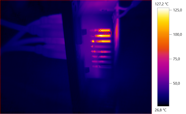
HS1: 127,2°C
HS1 is the transformer.
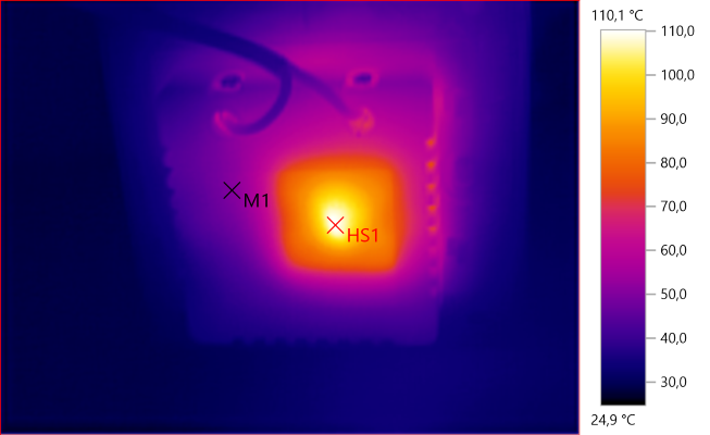
M1: 50,7°C, HS1: 110,1°C
HS1 is the transformer.
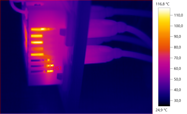
HS1: 116,8°C
Here HS1 is the two rectifier diodes, they may be able to withstand the temperature but the 105°C capacitor next to them can probably not.
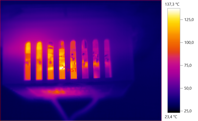
HS1: 137,3°C
HS1 is the transformer.
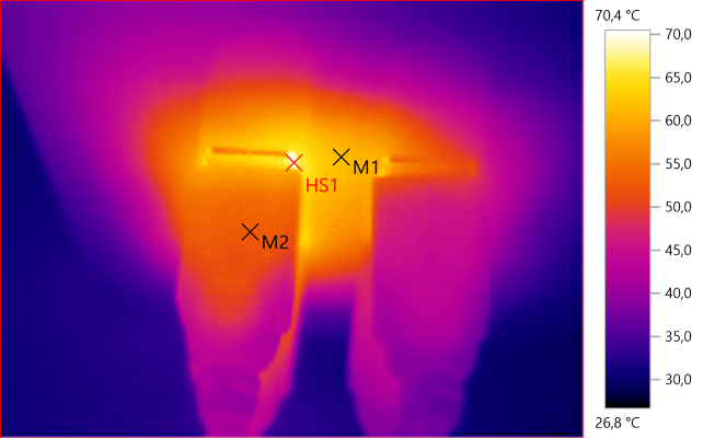
M1: 61,8°C, M2: 52,7°C, HS1: 70,4°C
The front is fairly warm.
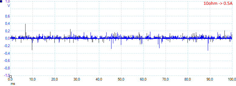
At 0.5A the noise is 26mV rms and 997mVpp.
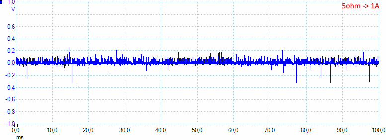
At 1A the noise is 30mV rms and 843mVpp.
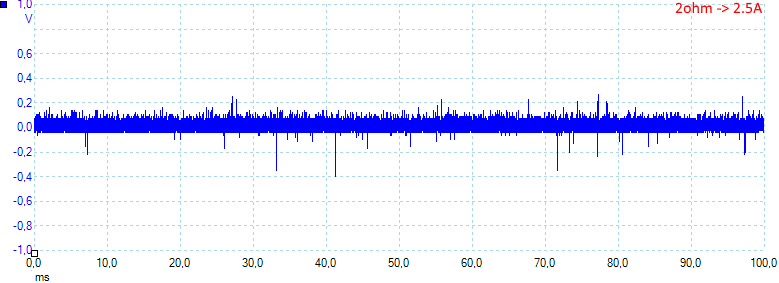
At 2.5A the noise is 49mV rms and 803mVpp.
Tear down
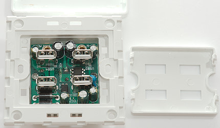
The protection plate was easy to unclip and the circuit board just needed removal of two screws.
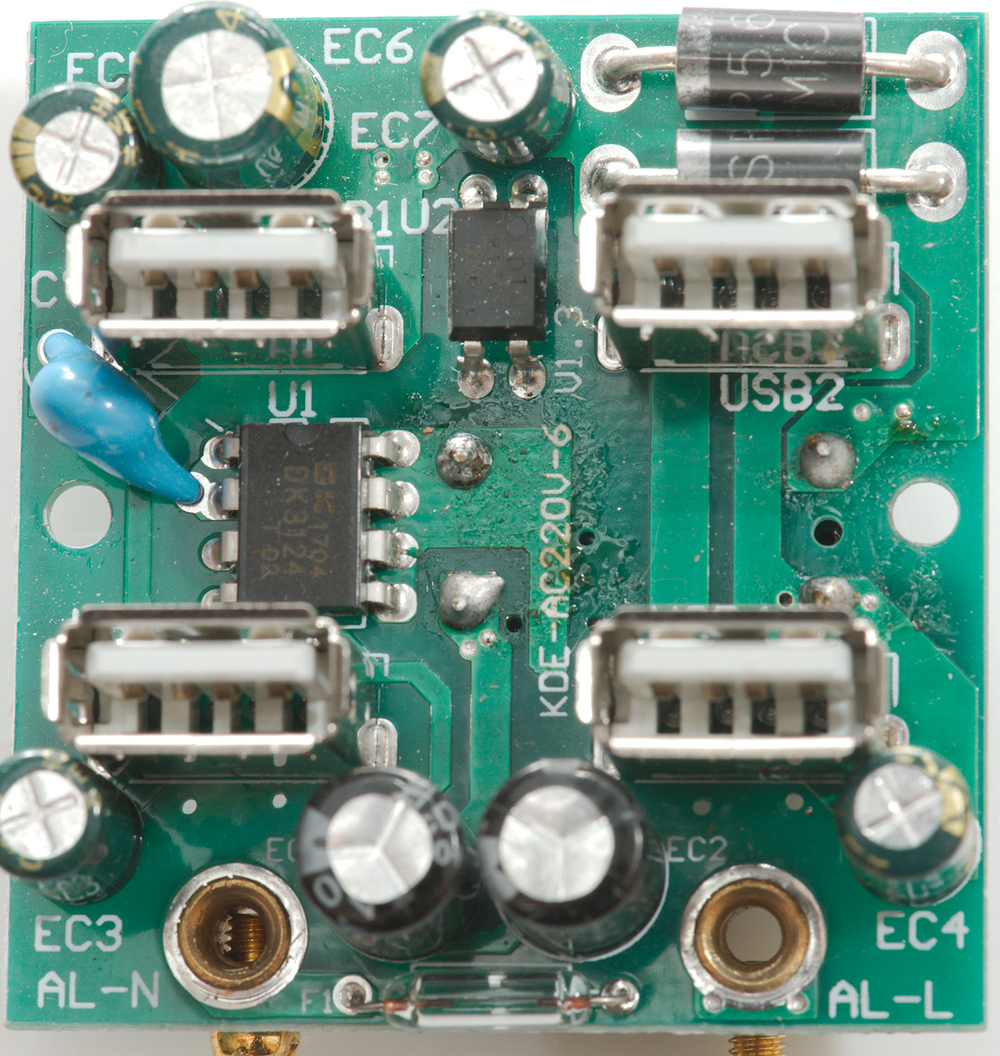
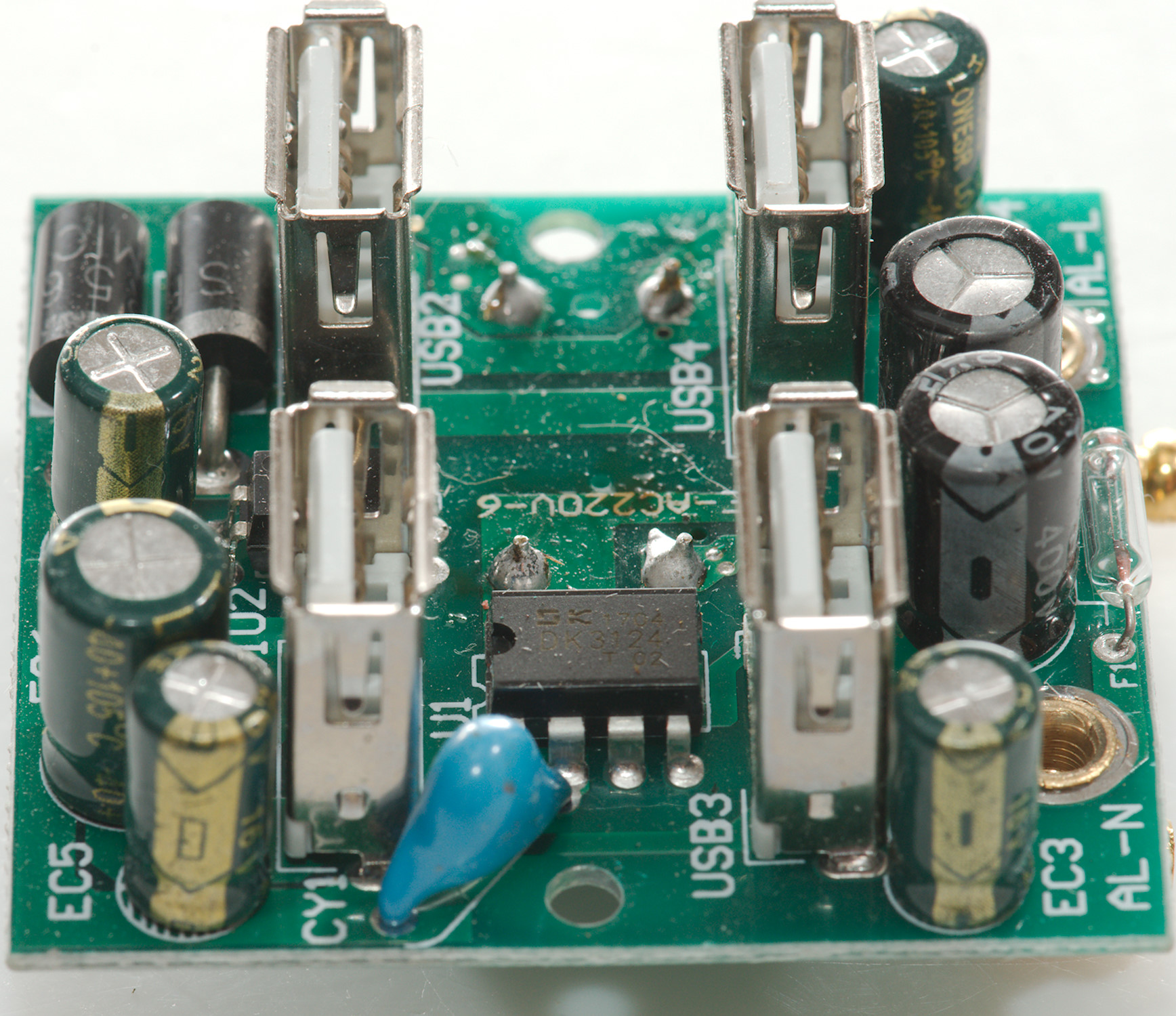
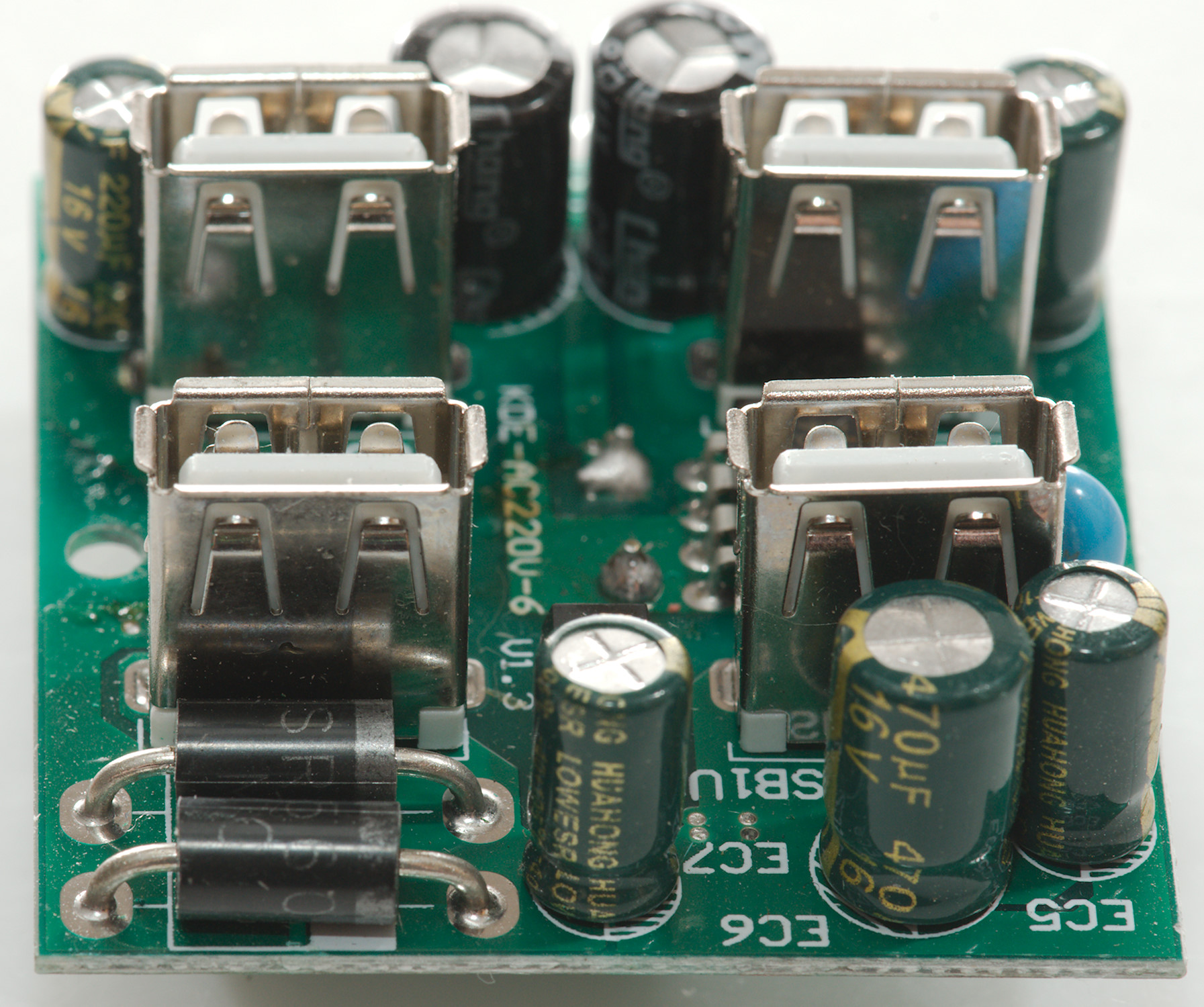
There is a glass fuse (F1) at the mains input, the switcher chip (U1:DK3124) is placed next to the safety capacitor (CY1). There is optical feedback (U2) and two rectifier diodes in parallel in the upper right corner.
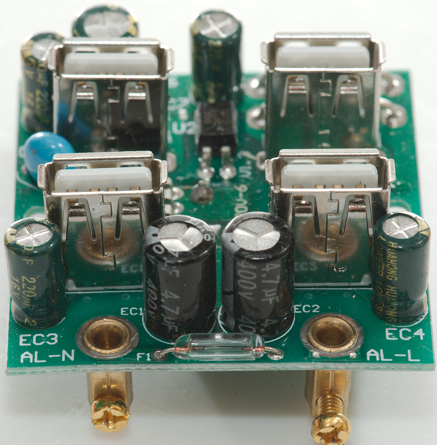
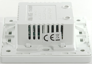
The first image has the fuse in front, on the other image it is the safety capacitor.
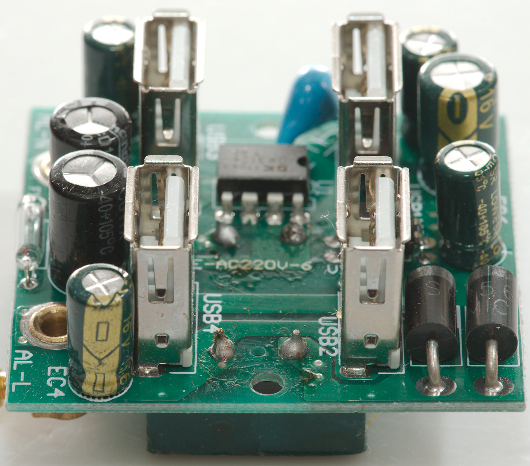
The first image has the two rectifier diodes in front.
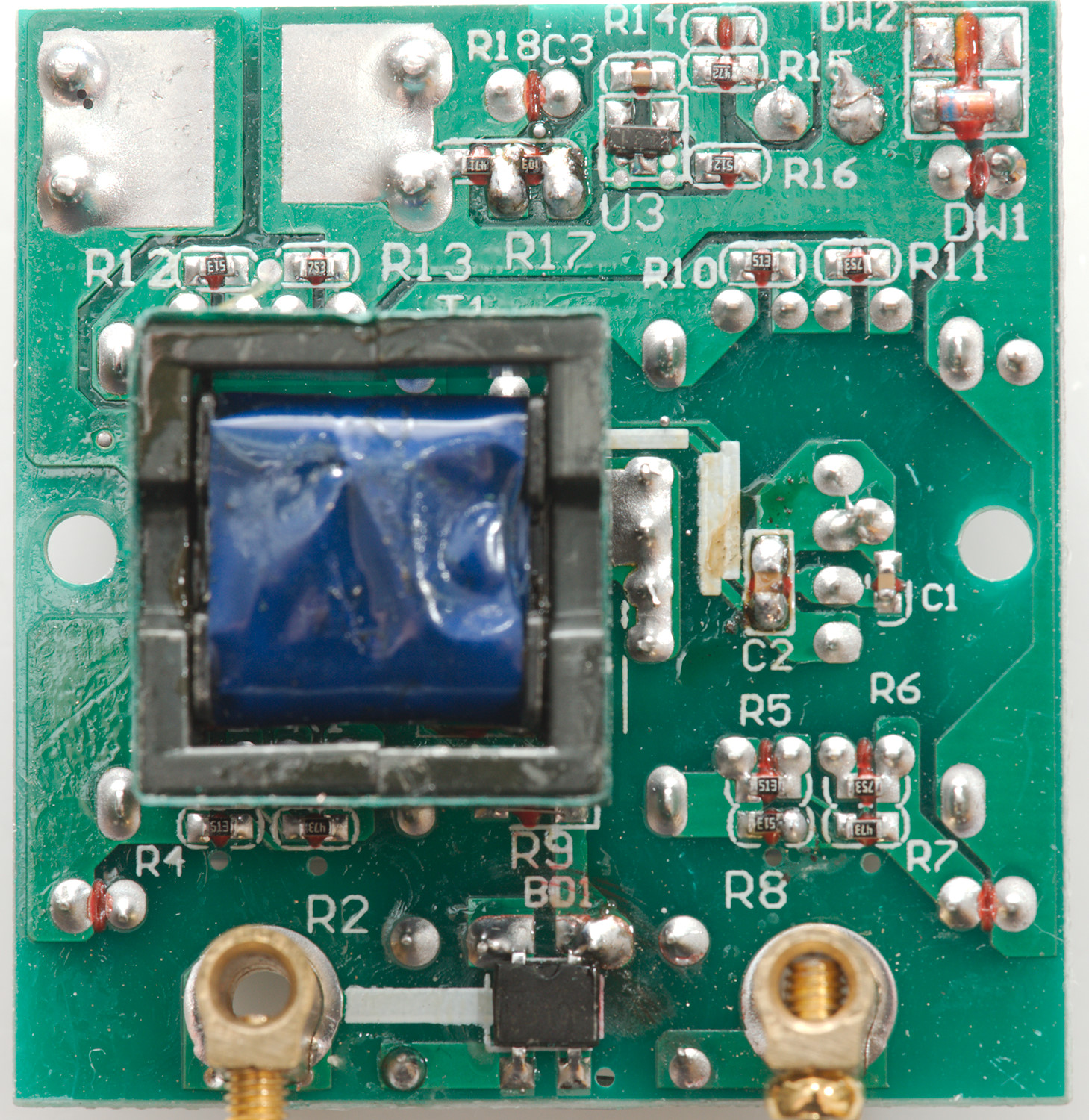
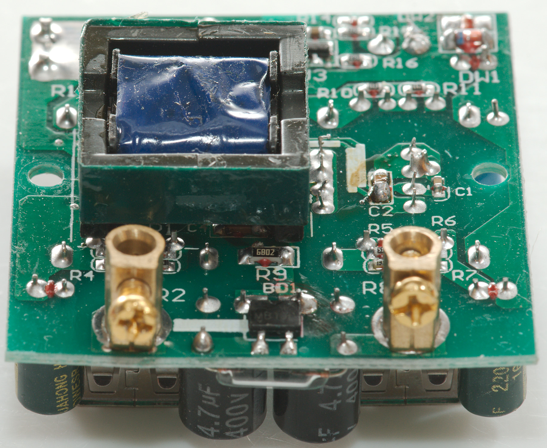
On this side of the circuit board is the bridge rectifier (BD1) and the transformer. There is also a reference chip (U3:431).
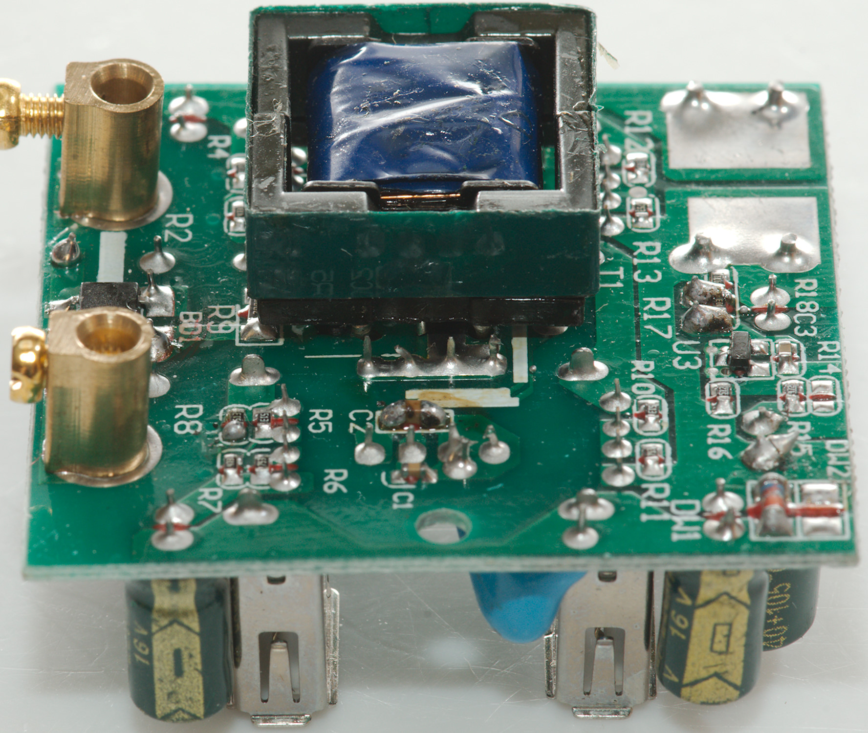
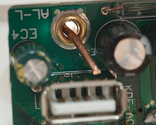
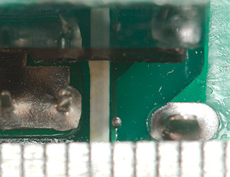
Safety is very bad on this, put wire with a long stripped part into the terminal and it may short directly to the usb shield. Safety distances is also non-existing, I believe it is about 1.5mm, instead of 6mm.
Testing with 2830 volt passed but 4242 volt between mains and low volt side failed.
Conclusion
It gets rather hot, even when tested in free air and it has very bad safety.
There is only one thing to say: Stay away from it.
Notes
Index of all tested USB power supplies/chargers
Read more about how I test USB power supplies/charger
How does a usb charger work?
