West Mountain Radio CBA HR (Battery analyzer)
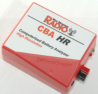
West Mountain Radio have two battery analyzers, this is the small version designed for lower current test.
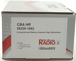
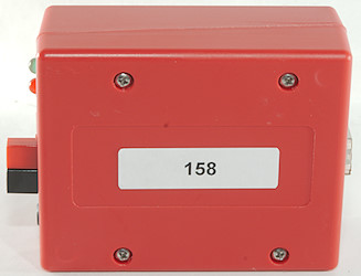
The box is a standard box for their battery analyzers with a sticker on saying exactly what is in the box.
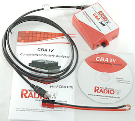
The box for this analyzer contains the analyzer, a usb cable, a test cable, a CD and a manual (Both software and manual can be downloaded).
In addition to the above I also got the thermosensor and 4 terminal adapter. Recording temperature curves requires the extended version of the software, that has to be bought separately (It is only a license code), this extended software also allows a more test modes. I also got this software.
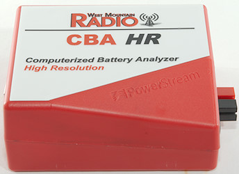
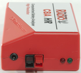
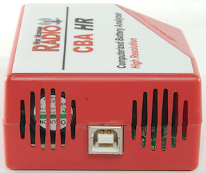
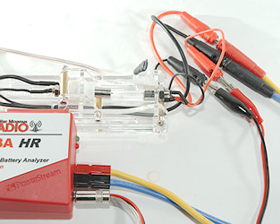
The CBA HR is only a box with a few connectors and indicators. There is a USB-B connector for connection to a PC, two power pole connectors for connection to the battery under test, a 3.5mm stereo jack for connection to the thermosensor and 4 terminal sense wires (Connections in the jack are described in the manual).
The box has a fan and it is always on when a test is active, even if the test is very low power.
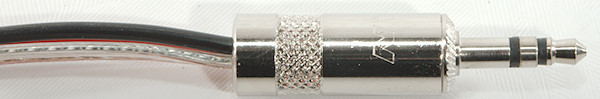
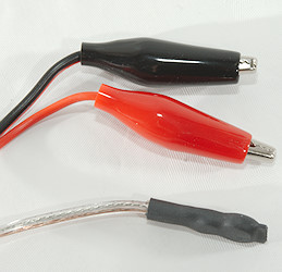
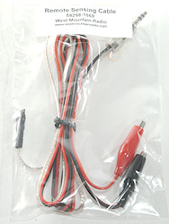
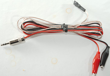
The thermosensor and 4 terminal cable has a NTC resistor with a magnet and two alligator clips for connection.
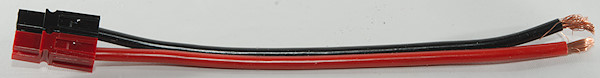
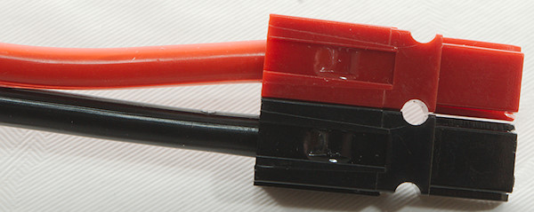
The supplied test cable is a pigtail and must be connection to some sort of battery holder or clips that can be attached to the batteries for test.
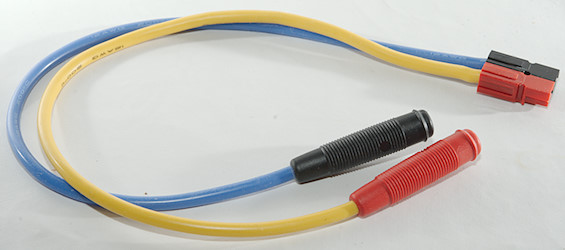
My test system uses banana plugs for most connections and I made my own test cable with some power pole connectors, thick silicone cable and banana plug sockets. Using extra connectors will increase the voltage drop, but here I am working with fairly low current and I have the 4 terminal adapter.
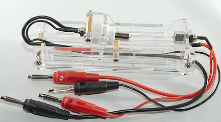
This matched perfectly with a 4 terminal battery holder from China.
And I was ready to test.
Testing and looking at software
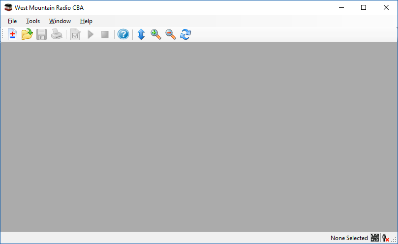
Starting the software I get this screen, pressing the ± icon will open the test start menu (After selecting a filename):
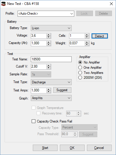
Where I fill in data about the battery I want to test and the actual test, the data about the battery do not need to be accurate, but helps the software with default values. The “Amplifier” is for the larger CBA and makes it possible to run high power discharges.
The most common test type is “Discharge” that is a standard discharge, but there are many other (See below). For running the same test many times a profile can be used, this will remember all the settings.
When “Start” is pressed the test specification window is closed and the test starts. While it is running the chart will be updated on the screen.
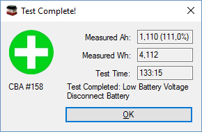
After some time you will get the test completed message. If you want both Ah and Wh, this is the only time it is available in numeric format.
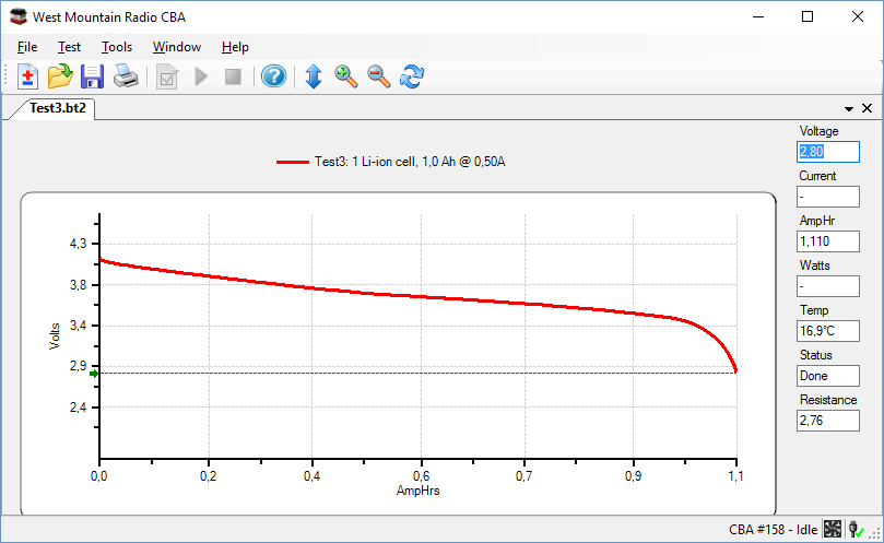
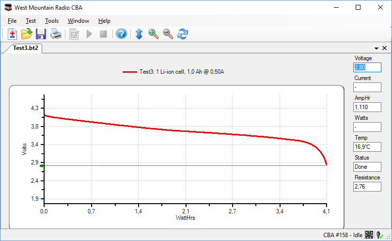
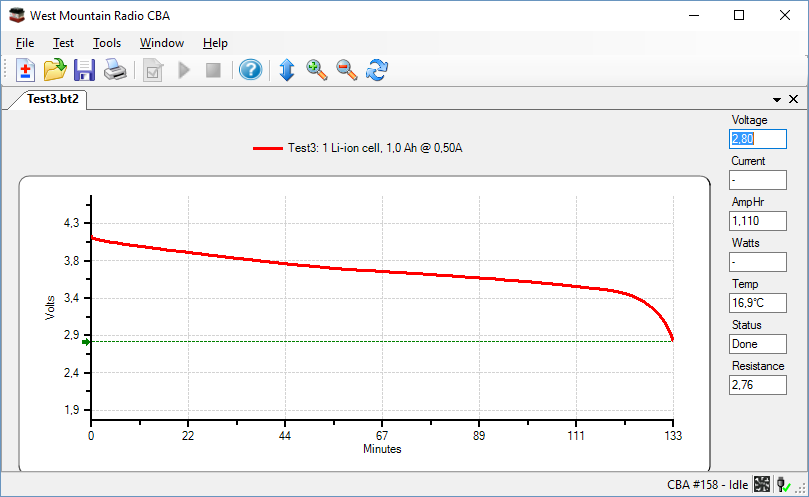
The final result can be viewed different ways, depending on selected chart type (Use Test, Chart Properties to change at any time).
It is possible to zoom in/out and move around in the chart. Other charts can also be imported for comparison. Pressing the diskette symbol will save the chart for later.
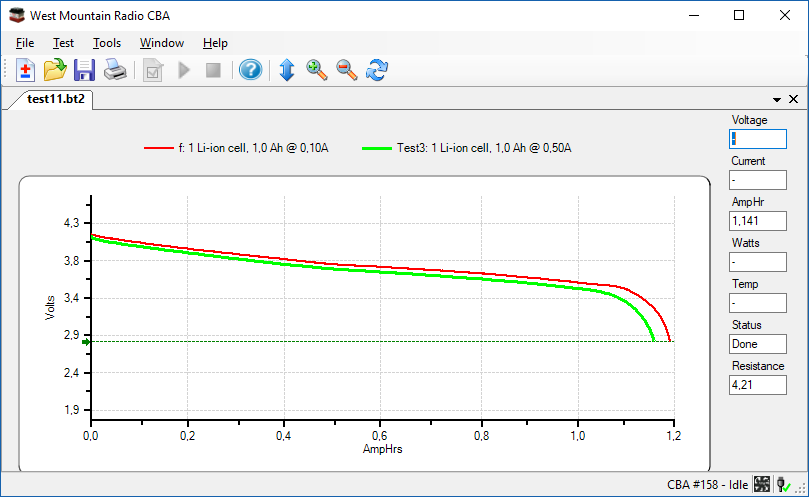
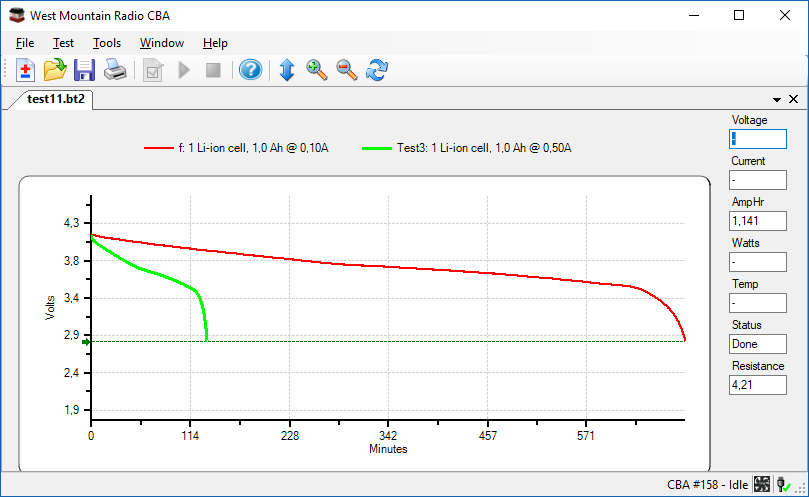
I did a discharge curve at another current and added it to the same chart for easy comparison.
Testing modes
The software has many testing modes, here is a short list:
-
Mission profile. Draw a constant current for a specified time, result is a pass/fail, depending on if the battery could do that.
-
Discharge. Standard constant current discharge
-
Charge monitor. CBA will only record voltage and not do any discharging.
-
Timed discharge.* Discharge battery to a specified percent of capacity.
-
Power profile. Test with automatic increasing current, this shows what a battery can do.
-
Duty cycle. Discharge with pauses, i.e. x seconds on and y seconds off.
-
Constant power.* Power draw will be constant, i.e. current will increase with lower voltage.
-
Multiple discharge. Use a table with current and time.
-
Constant resistance.* The CBA will simulate a resistor.
-
Dynamic. Constant current discharge, but it is possible to manually change current during discharge.
*: Requires the extended software
Export of data
The program can save in CSV files, but they are not standard format.
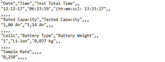
The first part of the file contains a header with the test data, but I wonder why it only includes Ah, why not always include both Ah and Wh and preferable in full resolution.
![]()
With more advanced tests it will also include more specifications.
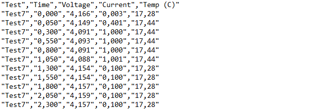
After the header follows the data, but not in a numeric format, the quotes says it is text. I would have preferred the numbers to be in numeric format.
Note: CSV exist in two standard formats depending on country:
decimal point=. and separator=,
decimal point=, and separator=;
Testing for an application
Because the software can do discharges with pauses or multiple currents (Extended version), it is possible to simulate real word application and see how long a battery will last under specific conditions. Here I will show an example.
Note: The parameters are selected to get sensible test times, not to simulate real world usage.
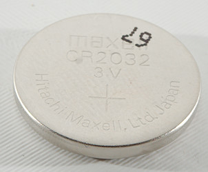
This CR2032 is very common for small applications, how much power can it deliver.
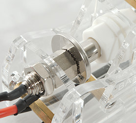
The battery holder works perfectly for this type of batteries.
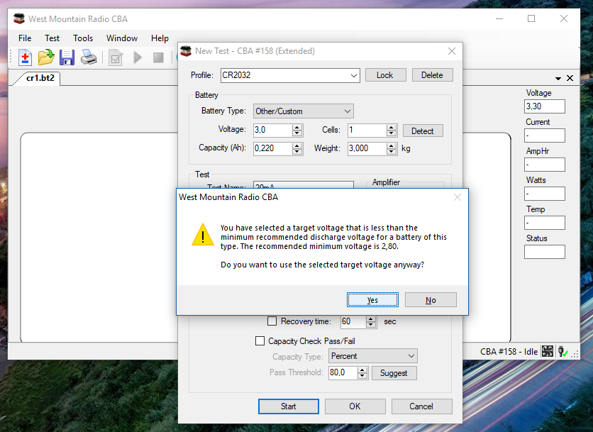
I got a warning when setting this battery about termination voltage, the software was using LiIon termination levels on this custom battery. Not a real issue because I could override the warning.
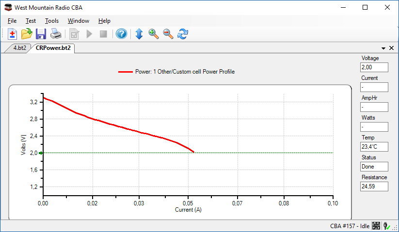
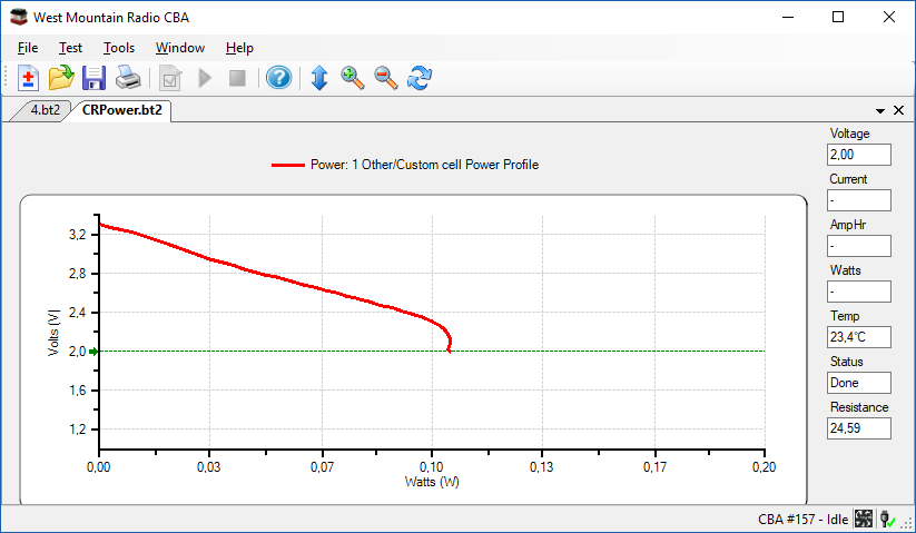
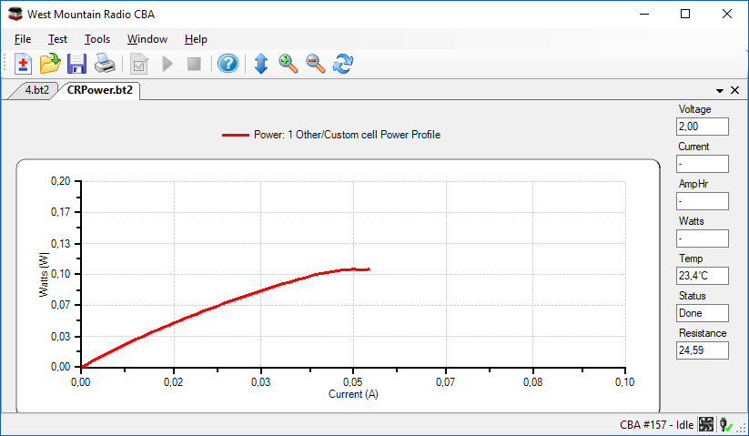
With one test I can generate these 3 curves. The battery can deliver up to 50mA, before voltage drops to 2V (With a fresh battery).
Lets use this battery in an application that draws 20mA for 20 seconds, at regular intervals, our system works down to 2V. How long will the battery last?
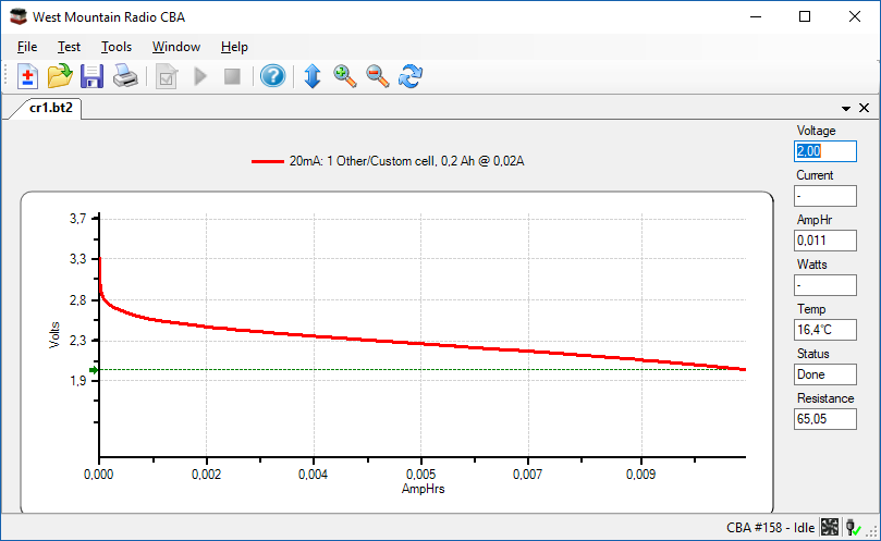

A constant current of 20mA says 11mAh and that is 33 minutes. That is not really a correct test, because we do not want to draw 20mA constant current, but only for 20 seconds and then some rest time, do this change anything?

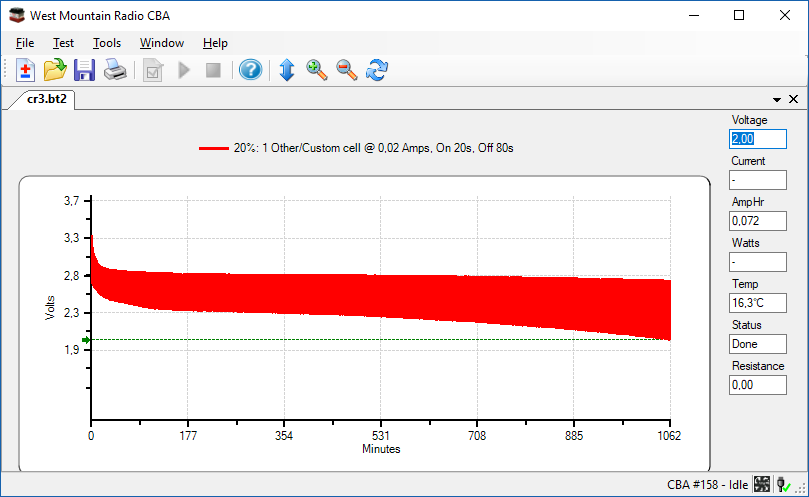
Here I did a test with 20 seconds on and 80 seconds off to simulate that, it did improve the capacity and time. This time I got 72mAh and 1062 minutes.
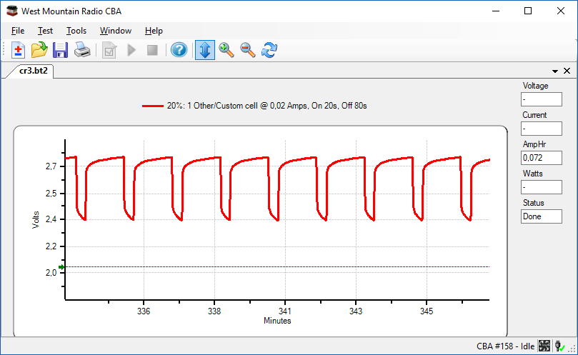
The thick line is because the battery recovers between each 20mA discharge, here I have zoomed in on the time curve.

The average current above is 4mA, what about just testing at 4mA?
The answer is no, the above curve shows 102mAh in 1543 minutes, that is not the correct result.
Measurements
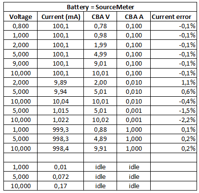
My first test was with a SMU where I can generate a voltage and measure the current while monitoring both voltage and current with high precision. Both voltage and current is precise. And even the lowest current setting (1mA) has a fairly good precision.
When idle the CBA will draw some current from the battery, how much depends on voltage.
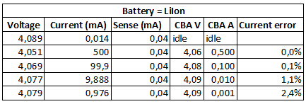
Lets try a battery instead and see if it gives the same results. Here the voltage is mostly fixed, but I can change the current.
If you are going to do many test at same current, it is possible to calibrate the CBA at that current.
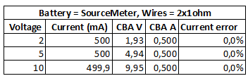
For the last test I wanted to see how good the 4 terminal connection was. For that I added a 1 ohm resistor in each current lead, as can be seen the voltage is about the same as the battery, i.e. the two 1 ohm resistors are compensated out. Or are they?
Some more testing showed that it was not a true 4 terminal sense, minus is not four terminal, but has about 0.1ohm between sense and current terminal (Probably the wires).
There as also another detail: It is important to disconnect sense leads from battery or remove battery, before (un)plugging the mini jack (It will short + sense to - current terminal shortly).
The discharge window do also show resistance and that is the internal resistance of the battery (and wires). A fast test shows it is fairly precise.
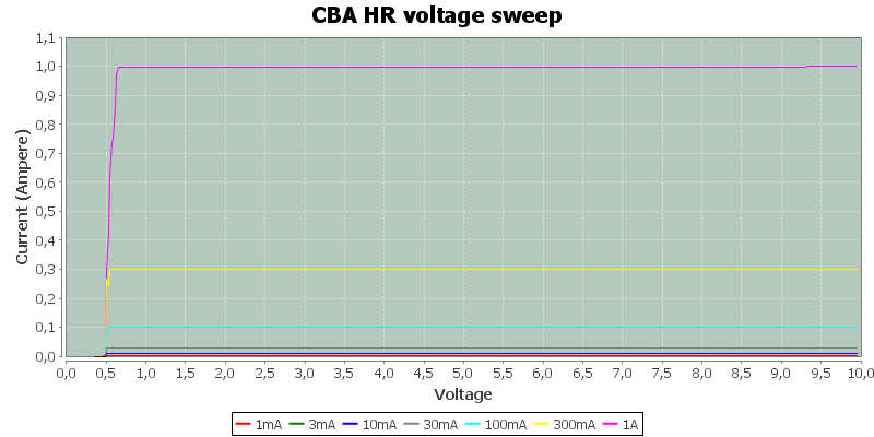
Here I have swept the voltage while measuring the current. The current is fairly stable and it works down to 0.7V
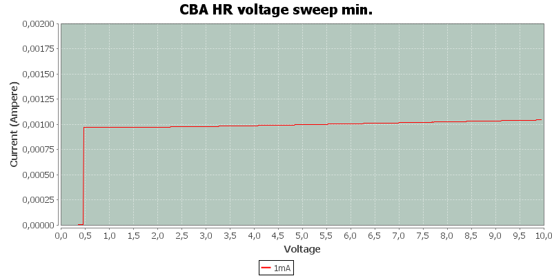
The lowest current (1mA) is a bit more unstable and works down to 0.5V.
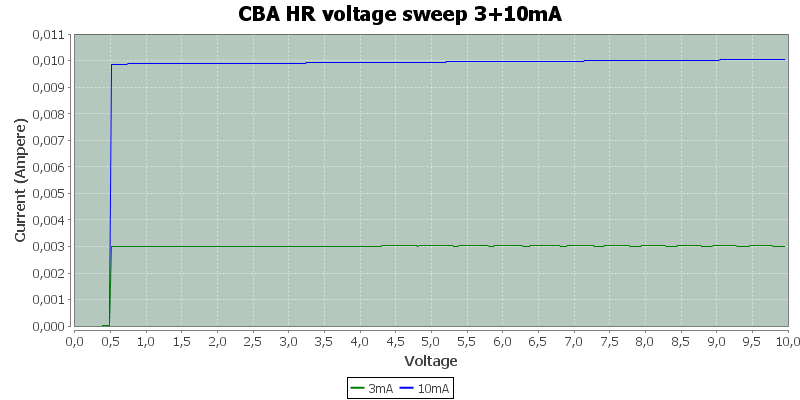
In the table the 10mA curve had tolerances both over and under, how do the curve look?
As can be seen it has a slight variation with voltage.
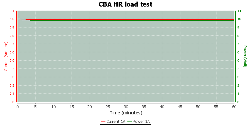
A one hour test at about maximum power. The current drops a bit when the CBA heats up.
I measured a total of 0.993Ah and 9.831Wh, the rapport from CBA HR said 1.001Ah and 9.830Wh.
The temperature photos below are taken about 45 minutes into the one hour test.
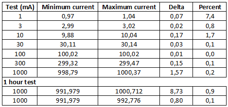
Finding maximum and minimum in the curves and divide by the current gives the maximum tolerance over voltage. It is not surprising that the tolerance is higher at lower current, but it is still good.
The one-hour test is within 1% and that tolerance will be much smaller if the CBA has time to heat up first. The second line (0.1%) is calculated from 5 minutes to 60 minutes, i.e. after the CBA has heated up.
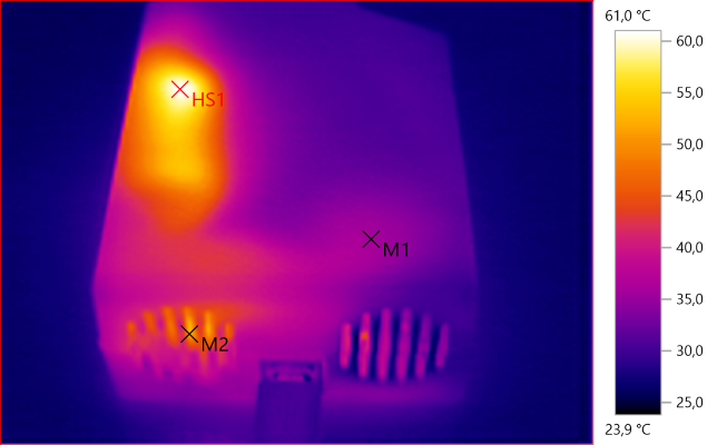
M1: 35,9°C, M2: 51,8°C, HS1: 61,0°C
The heat is generated in one side of the CBA and the fan is blowing air out.
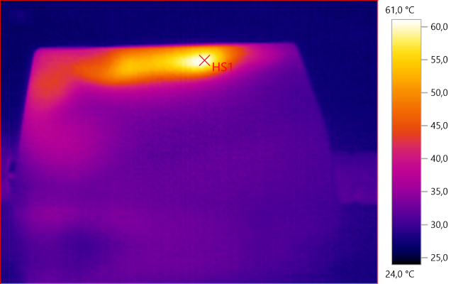
HS1: 61,0°C
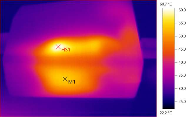
M1: 53,6°C, HS1: 60,7°C
The higher temperature can be seen on the side also.
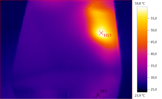
M1: 32,6°C, HS1: 59,8°C
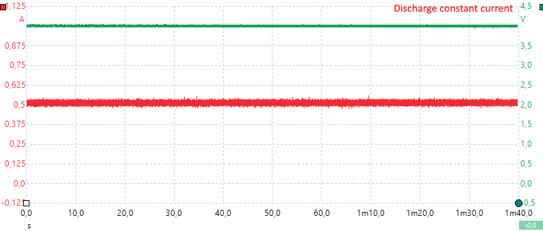
A constant current discharge looks constant on a oscilloscope.
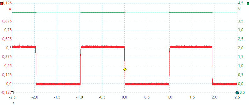
Using a fast duty cycle test with 1 second on and 1 second off, the load looks like above.
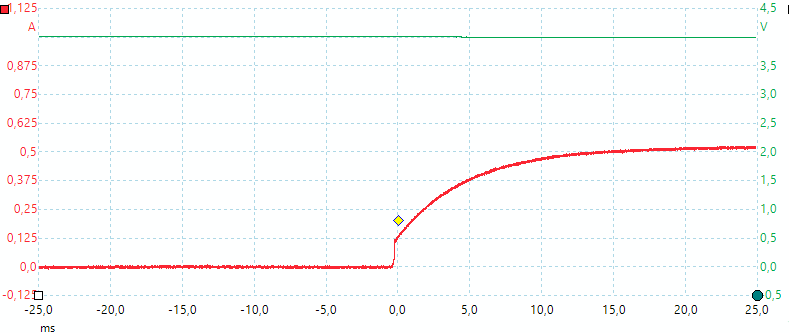
A closer look at the on shows that i takes about 10ms to turn the current on.
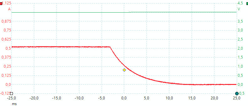
And about the same to turn the current off.
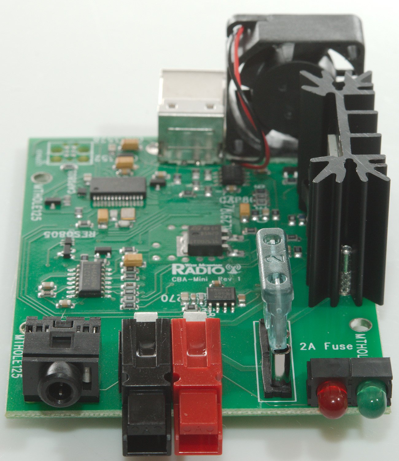
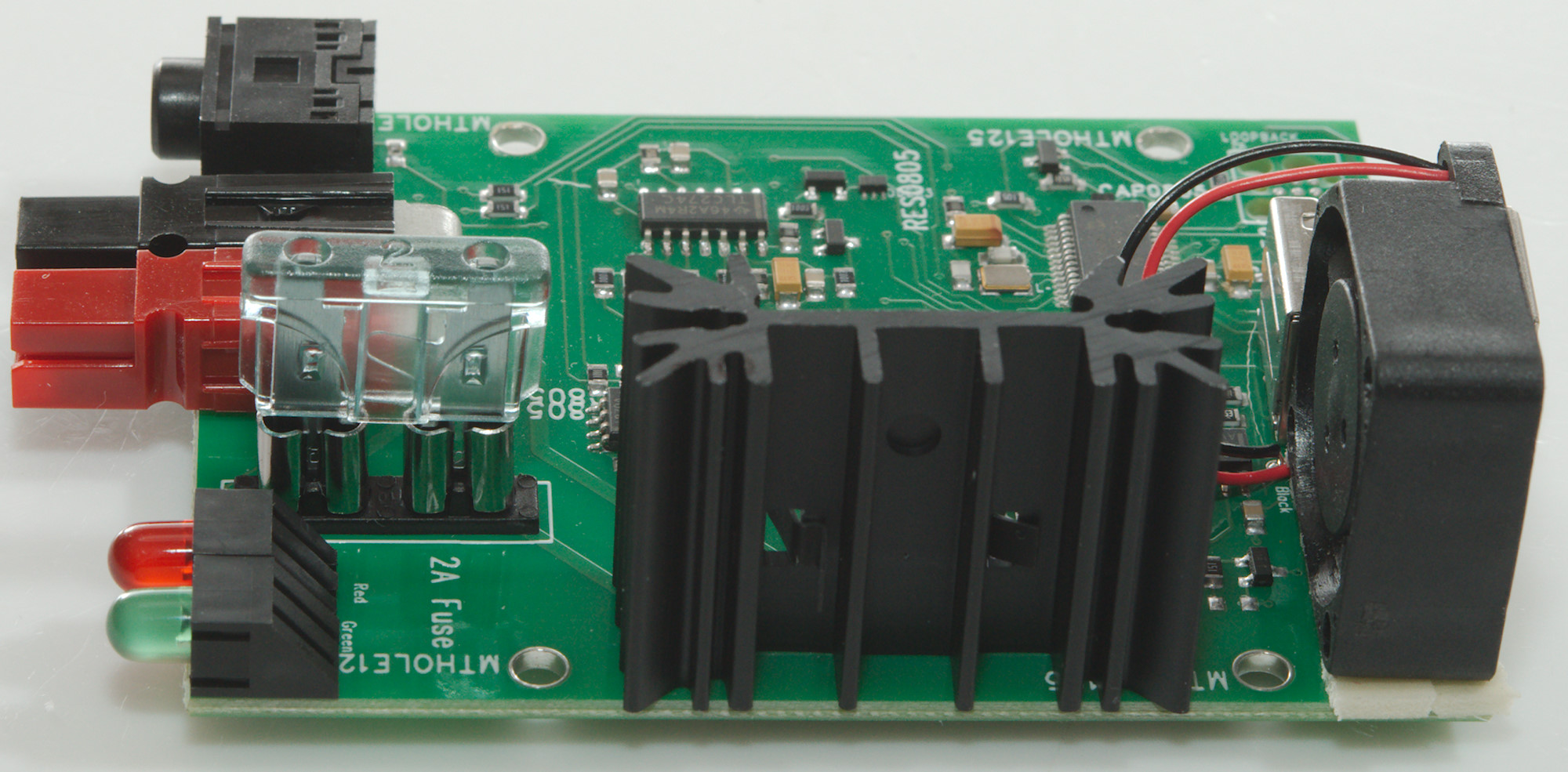
Tear down
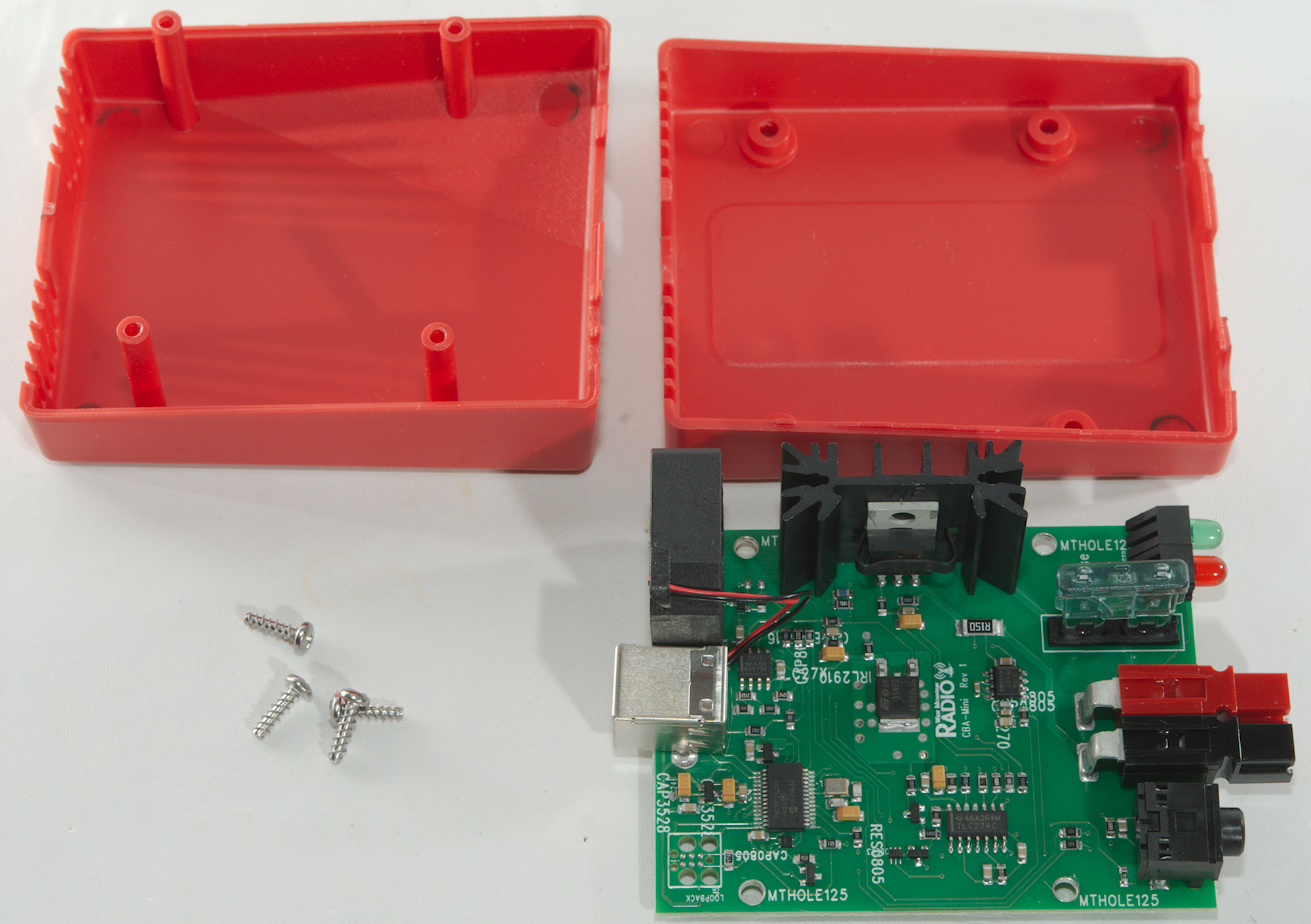
It is very easy to open, just four screws and the circuit board is loose.

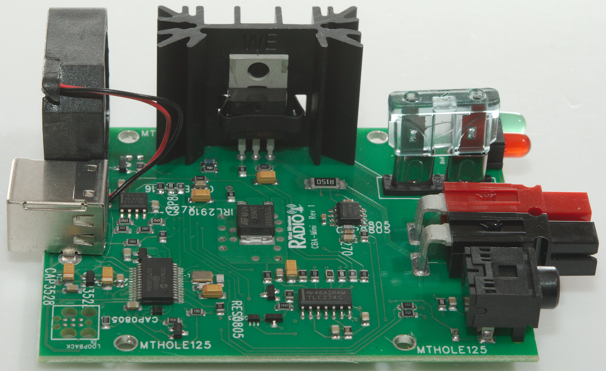
The construction has a microprocessor (PIC18F26J53), two OpAmp (LM324 & TLC272C), a current sense chip (INA270) and two mosfets, one on heatsink and one on the circuit board.
There is placed a 2A fuse on the + connection, i.e. if something goes wrong, this may protect from fire.
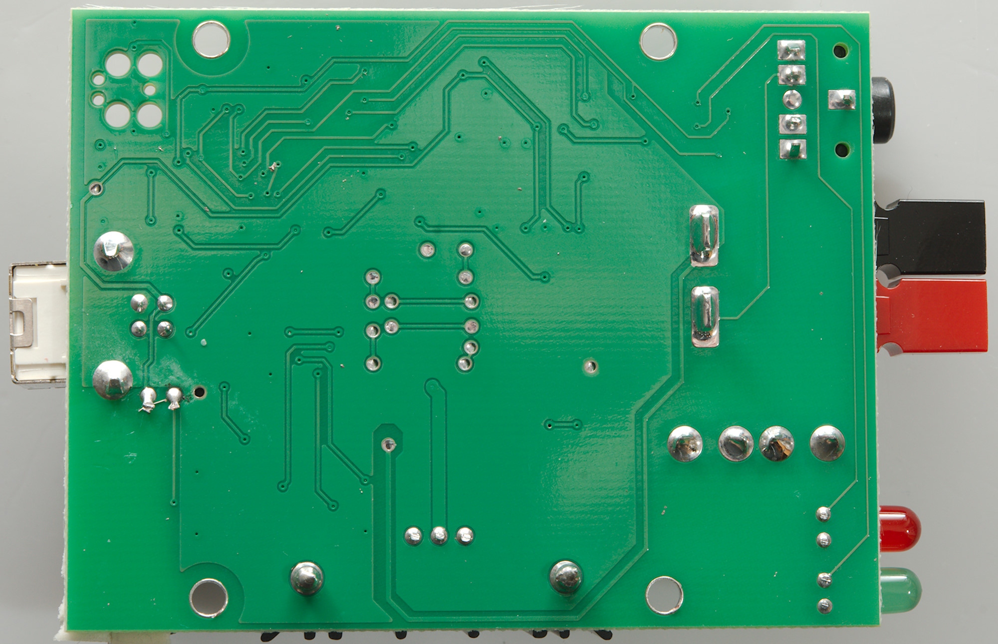
There is nothing on the other side.

Conclusion
The CBA HR is fairly precise and practical. It can be used to measure battery capacity for smaller batteries, but where it really is interesting is to estimate life time with some specific load, and it can simulate variations in the load.
The 4 terminal do not really work, but is not needed at 1A, just use thick wires.