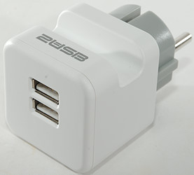
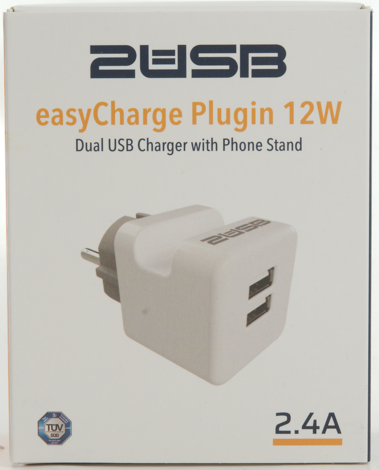
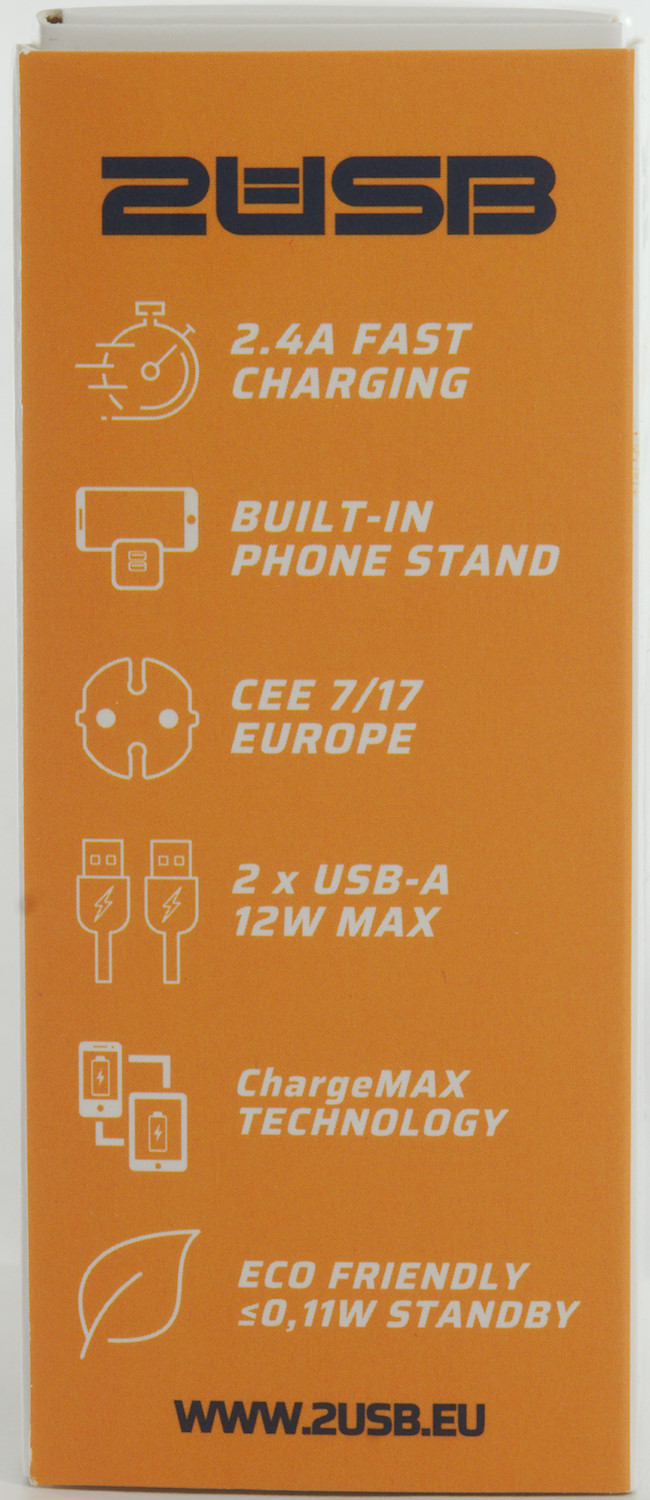
2USB easyCharge Plugin 12W
Official specifications:
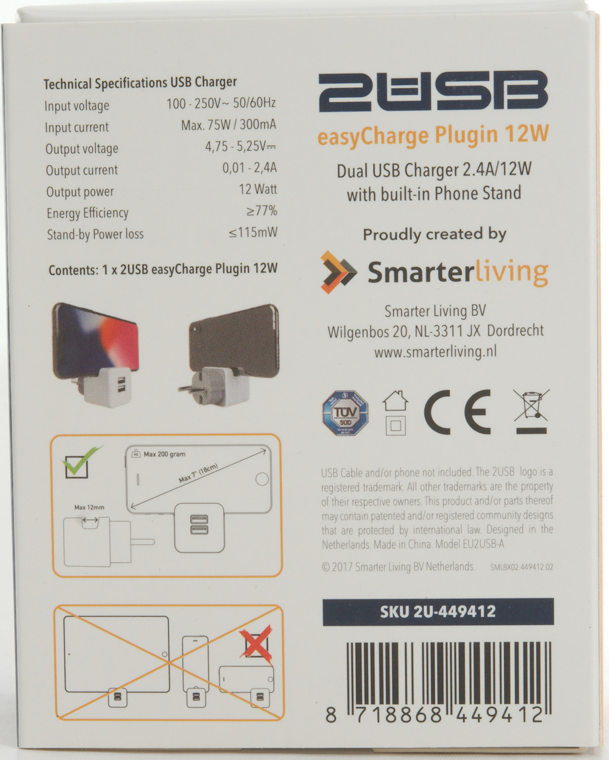
-
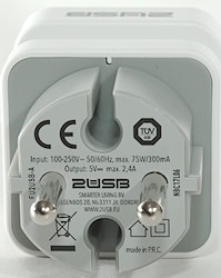
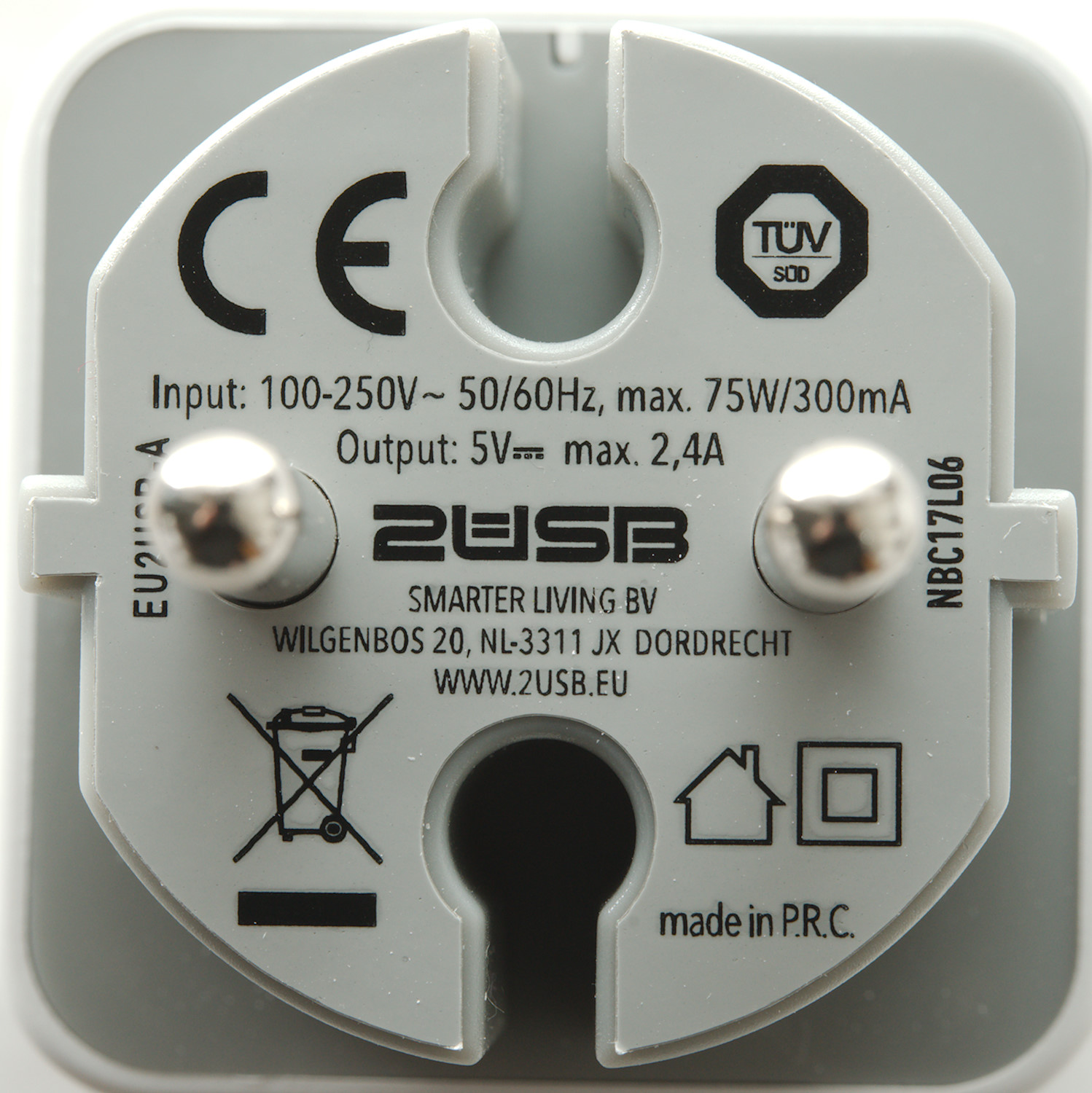
Input voltage: 100 - 250V 50/60Hz
-
Input current: Max. 75W / 300mA
-
Output voltage: 4.75 - 5.25V
-
Output current: 0.01 - 2.4A
-
Output power: 12W
-
Energy efficiency >=77%
-
Standby power loss: <=115mW
The cardboard box only contained the charger.
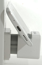
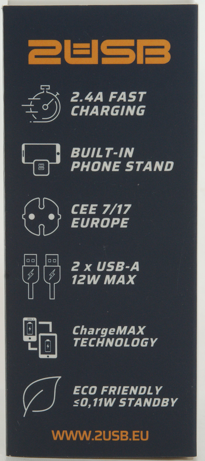
With plug-in chargers it can often be problematic to use a short cable for best charging, because there is no place for the phone. With this charger it is possible to place one phone on it.
Measurements
-
Power consumption when idle is 0.068 watt
-
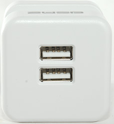
USB outputs is auto coding with DCP, Samsung and Apple 2.4A
-
Both outputs are in parallel.
-
Weight: 42.6g
-
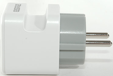
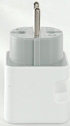
Size: 76.7 x 44.3 x 44.3mm
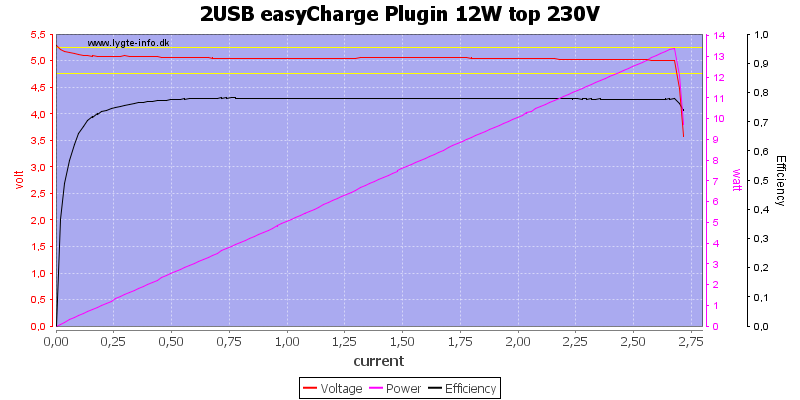
The charger can deliver about 2.7A on the top usb output.

And the same on the bottom usb output.

When both are used together the total current is the same, here at 120VAC
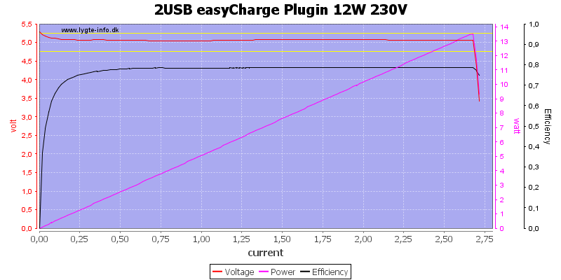
And at 230VAC.
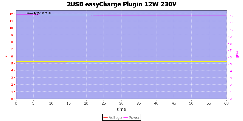
The charger has no problem delivering 2.4A for one hour.
The temperature photos below are taken between 30 minutes and 60 minutes into the one hour test.
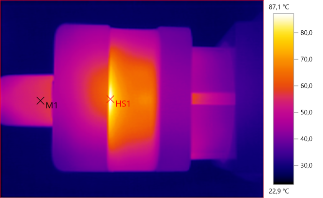
M1: 55.6°C, HS1: 87.1°C
HS1 is the rectifier diode.
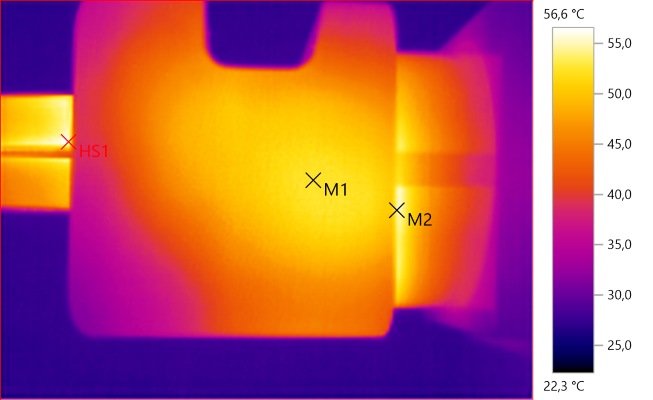
M1: 52.8°C, M2: 54.0°C, HS1: 56.6°C
M1 & M2 is the transformer.
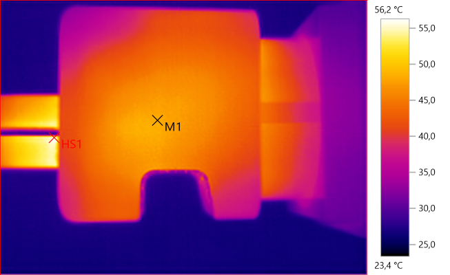
M1: 48.2°C, HS1: 56.2°C
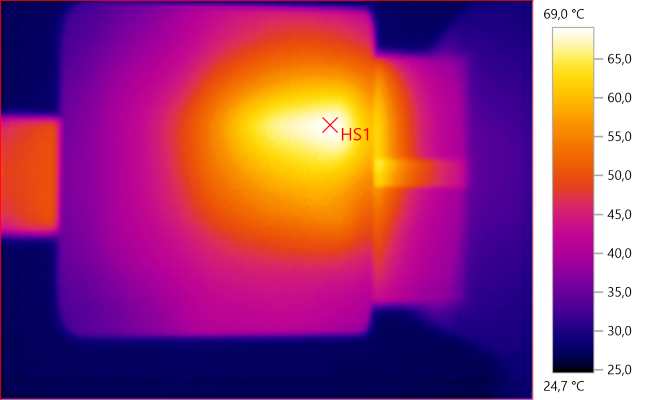
HS1: 69.0°C
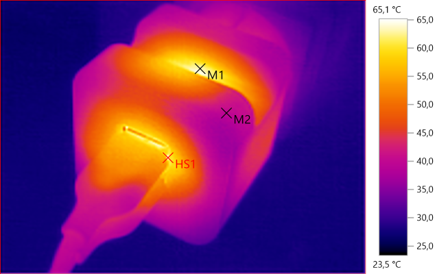
M1: 63.0°C, M2: 39.7°C, HS1: 65.1°C
The front is probably headed from the rectifier diode.
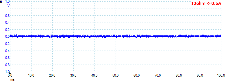
Noise at 0.5A load is: 15mV rms and 142mVpp.
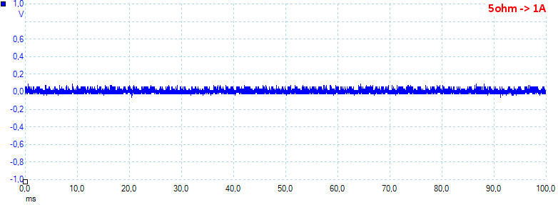
Noise at 1A load is: 26mV rms and 179mVpp.
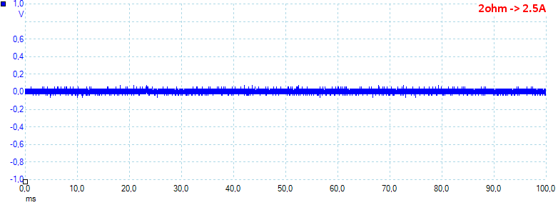
Noise at 2.5A load is: 27mV rms and 173mVpp, generally a very low noise.
Tear down
The lid was mounted with clips, when removed there is two screws and when they where removed there was one more screw.
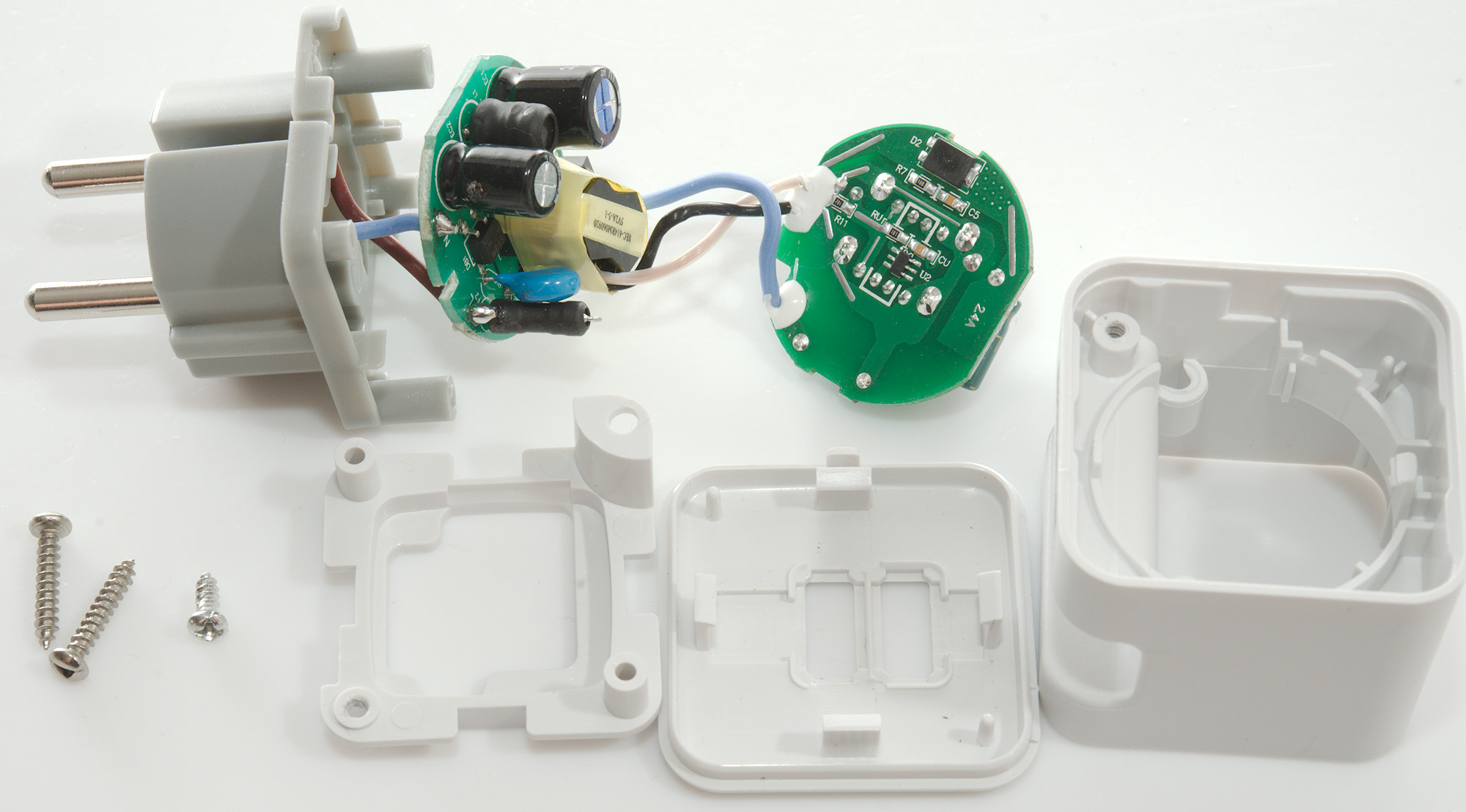
Then all the electronic could be taken out. There is not really access to anything mains connected before at least one screw is removed.
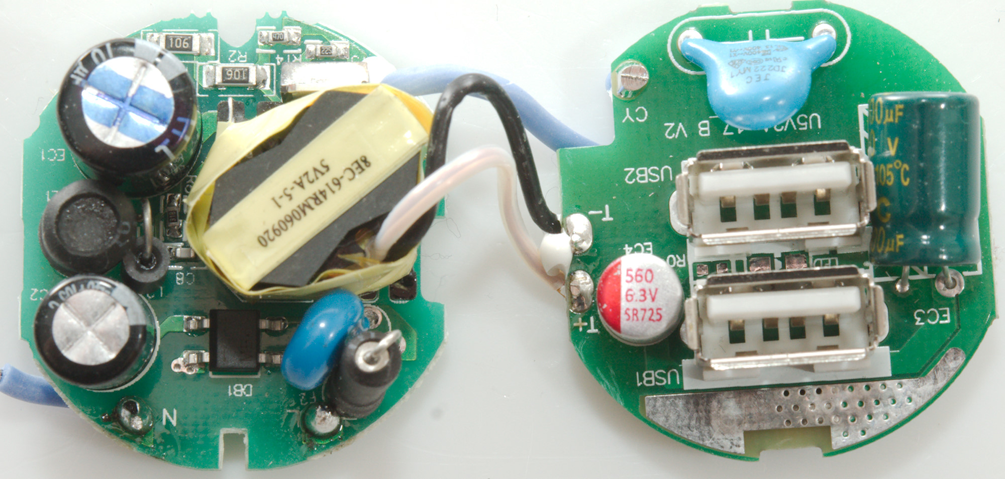
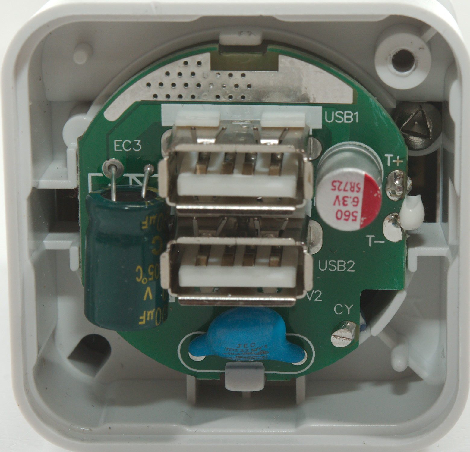
One circuit board with mains stuff, there is a fuse (F2), transient protection (RV1: MOV), bridge rectifier (DB1). Between the two smoothing capacitors is a inductor (L1) and a ferrite bead (L2) and at the top next to the transformer is the switching transistor.
On the low volt side is the safety capacitor (CY1). This means there is a mains connection to the low volt side (Blue wire).

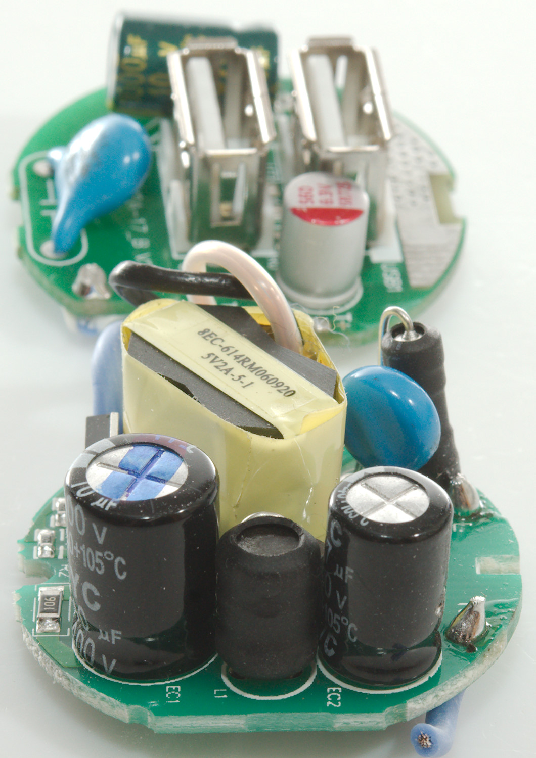
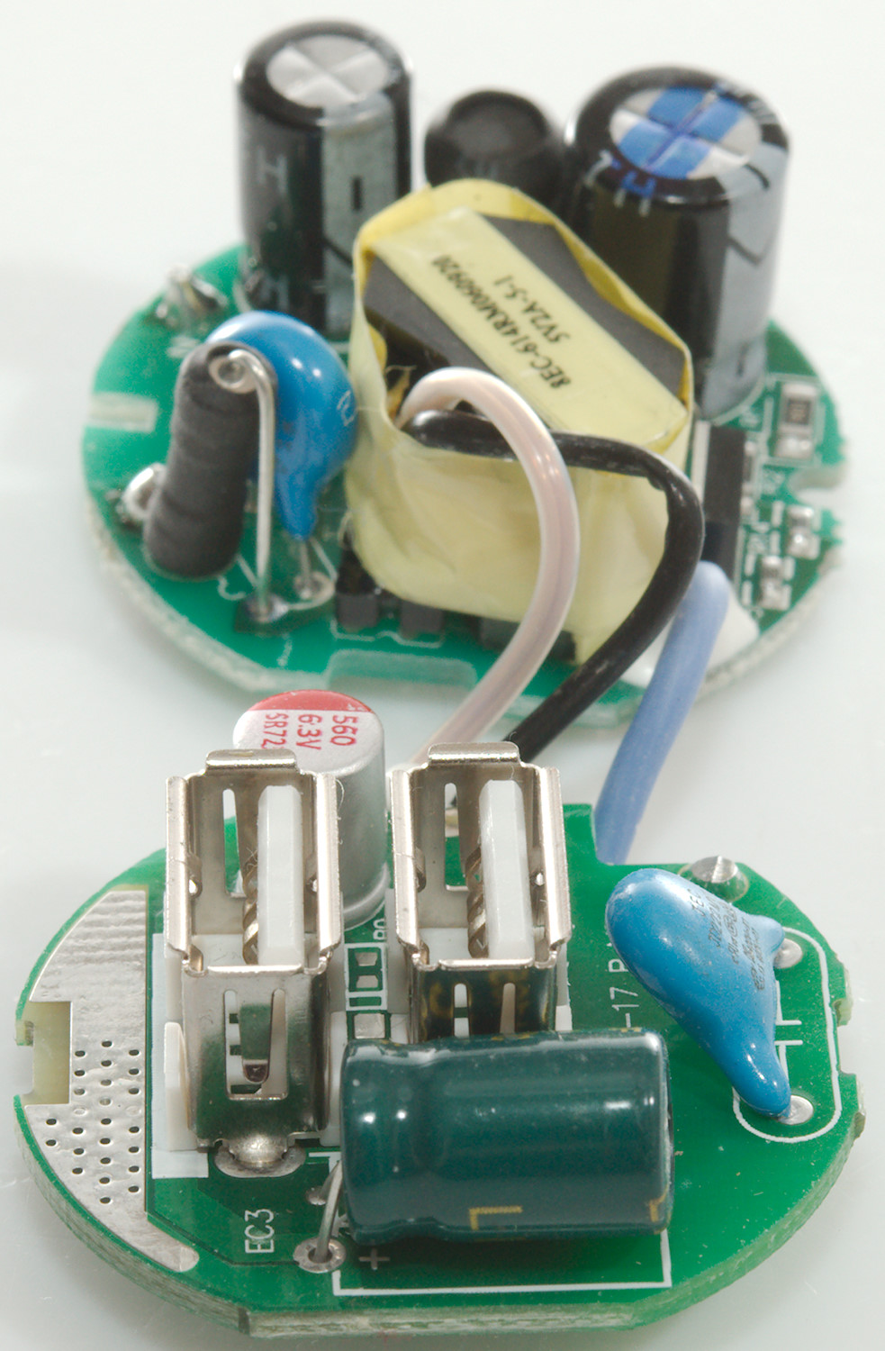

From this side the safety capacitor and the switcher transistor is very easy to see.
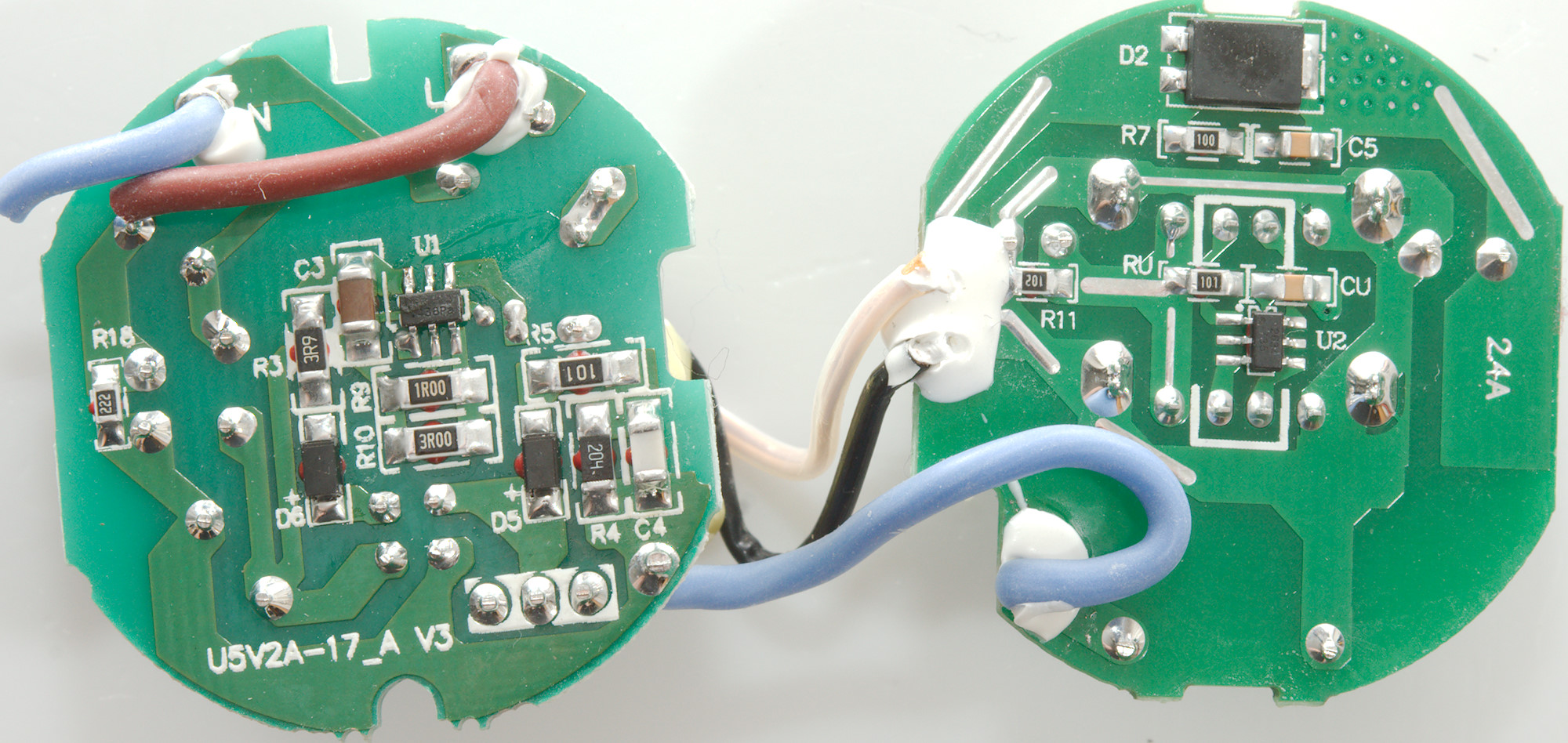
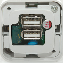
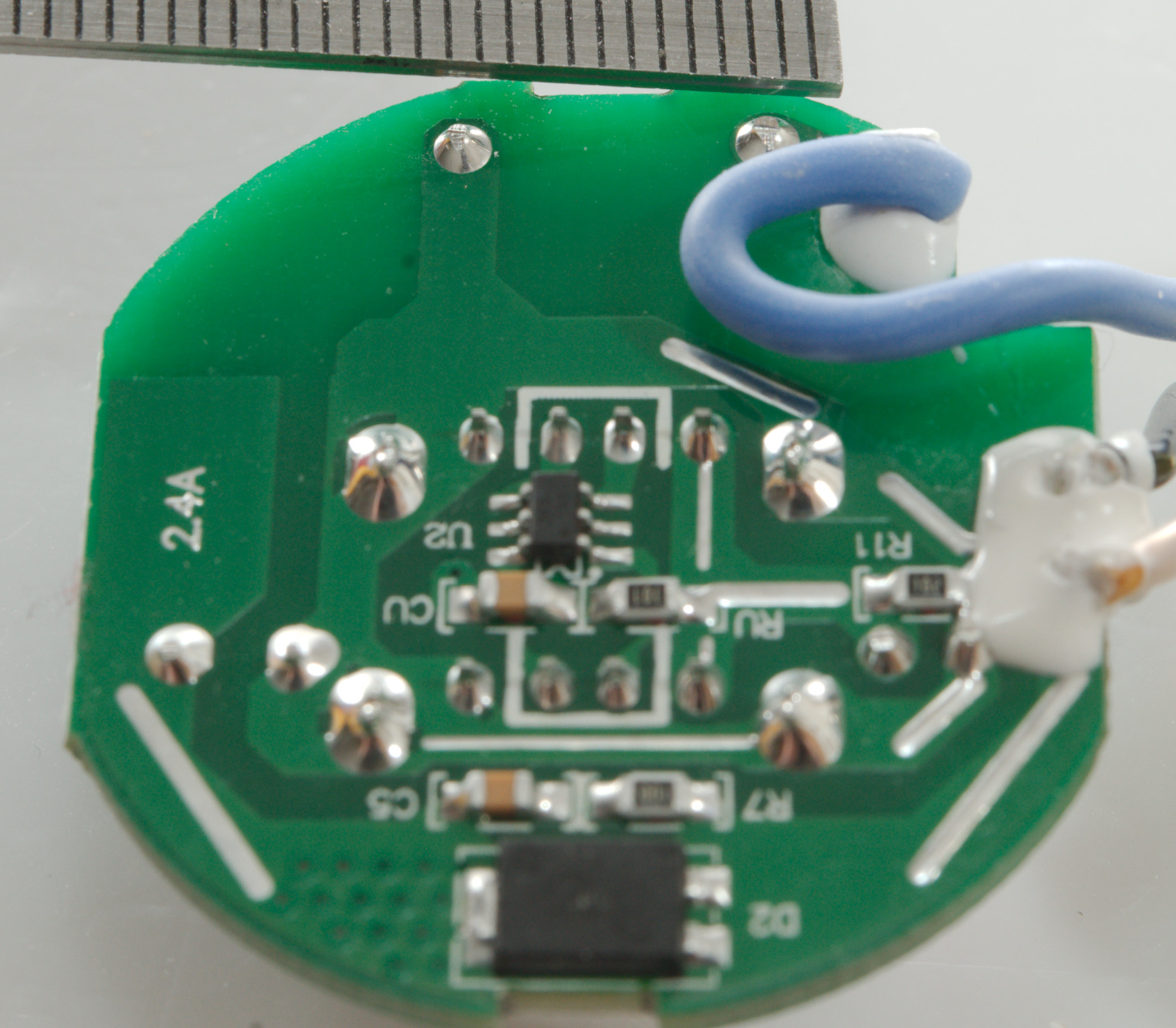
On the mains circuit board is the switcher controller (U1), on the low volt board is the rectifier and the auto coding chip (U2).
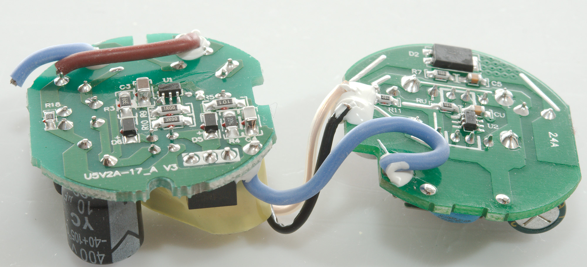
The safety distance on on the circuit board is good. Another interesting distance is between the two circuit boards, I got it to between 6 and 7mm from the top of the capacitor to the top of the rectifier diode, this is more than good enough.
Testing with 2830 volt and 4242 volt between mains and low volt side, did not show any safety problems.
Conclusion
The usb charger has low noise, automatic coding, good safety, the power is a bit low for a two output charger, but enough for a single power hungry device.
Notes
Charger was supplied by a smarterliving.nl for review.
Index of all tested USB power supplies/chargers
Read more about how I test USB power supplies/charger
How does a usb charger work?