I recently bought a Zanflare C4 charger in addition to my MC3000 and Gyrfalcon All-44 as it is known to be quite accurate, easy to handle and well-rated by our helpful Danish expert HKJ.
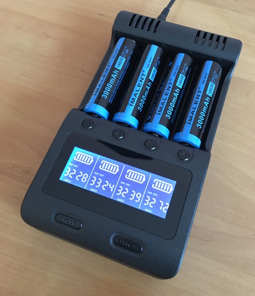
So, I made some capacity tests (NOR Test) first on my 8 brandnew protected Immalent batteries. The result was fine to me. All cells were charged to indicated 4.20V and had rather comparable capacities…
Three days later, 7 of these cells indicate 4.16V and 1 cell 4.15V when I measured it with my DMM. My conclusion is that the C4 terminates quite early with a rather high termination current, leading the voltage to drop by 0.03-0.04V right after cells were taken out.
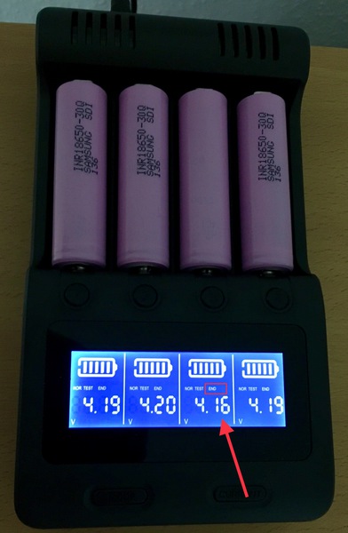
Now, I inserted 4 of my almost new Samsung 30Qs with joint-welded button tops. These cells were known to be very hard to handle with the MiBoxer C4-12 as the iR readout was always different and often beyond 250mOhms. Eventually, the C4 also had issues with the iR readout and so slot no. 3 (from left) indicated 398mOhms while the other ones were around 80-160mOhms…okay let’s cut the crap…
When the NOR test finished I was surprised to see that all slots would indicate different voltages between 4.16V to 4.20V. The measured capacity however was unsuspicious and okay in my humble opinion. Slot no. 3 took 30min longer to finish than the other ones.
Now, I doublechecked the actual voltage with my DMM. All values measured are the same as indicated on the C4.
Questions:
I am now wondering if the higher contact resistance of slot 3 is the reason why the voltage did not reach 4.20V or if this has nothing to do with it. Slot 1 and 4 also did not reach 4.20V.
I would like to know if an actual voltage of 4.16V is normal after 3 days of storage outside the C4 charger. Those 30Q cells had up to 4.19V right after they were taken out of the C4.
I‘m a bit concerned if these small deviations of up to 0.05V will have a harmful effect on flashlights with 4p or 4s configuration. For instance, I recently read that in a Meteor M43 (4p configuration) different voltages can let springs melt due to immediate voltage balancing.
Thanks a lot for any input that could help me to understand what’s going on here.
lt’s normal for cells to rest at 4.16v. l have even new cells rest down to 4.14v yet got discharge capacities at very near nominal specs in my iCharger.
A .05v volt difference could be wiped out in just one turbo session., and cells tend to equalise by themselves.
It’s normal for cells to have 4.19 to 4.18v immediately off the charger but will eventually settle to its resting voltage ranging from 4.17 to 4.14 in a day or two .
Smart chargers will always auto choose a lower charging rate when it finds a cell’s IR too high for its comfort, resulting in longer charging times.
The only thing I am still wondering about are the voltage discrepancies when the cells are still in the charger. I am not referring to the resting voltage right after the cells were taken out of the charger. I thought the cut-off voltage of 4.20V is always reached when cells are being charged. According to the 30Q button top cells, the one in slot no. 3 did not even terminate at 4.20V but at 4.16V already. Is the root cause for this behaviour to be found in the high contact resistance of 398mOhms at slot 3 or is there a different reason or just a random effect that this cell did not even reach 4.20V cut-off voltage?
Yesterday, I made a C>D>C cycle on my Acebeam 18650s (they barely fitted into the C4 by the way!). All went fine. All 4 cells were terminated at 4.20V, still indicated this morning after charging has finished some hours ago.
One more interesting fact:
After running C>D>C cycles on three different cell brands if found out that slot no. 2 always reaches the highest capacity. The deviation is always below 5%, so I assume no issues with a 4S-battery configuration but still it appears to be no coincidence that cells in slot no. 2 reach the highest capacity.
While the those chargers, the C4, MC3000, etc. are considered more advanced than the charger/analyzers of yesterday, still they are not laboratory-grade fine instruments that can measure the same figures all the time, same with the cells that we put in them. Try putting in a cell in the same bay and charger and repeatedly do the same test (IR, discharge capacity, etc.) and chances are results will always vary, some to greater extent, some to a lesser extent.
If one slot repeatedly gives out higher figures but within 100 mah, then it’s not much to worry about. Have you marked each cell, have a spreadsheet to record all their capacities, IR at what bay and charger?
If you don’t then there really no real basis to worry about IMO.
Edit: But one thing I notice with these smart chargers, they always react to cells with high IR, which by the way we don’t really know and not aware of before the advent of these chargers with digital displays.
People with hobby chargers are already aware of this behaviour however.
I have just started to put some tape/labels onto the shrink to mark each cell i.a.w. capacity and iR. Maybe it would make sense to do some kind of charging rotation between those cells and charging slots. The highest deviation I recorded so far was about 138mAh, so close to 5% more than the cell with the lowest figure. Mostly, it’s around 100mAh. I think I can live with that taking into consideration that the Zanflare C4 was much cheaper than the MC3000.
Thanks for the hint. That’s exactly the next thing I want to find out - just for comparison. However, it will be difficult to reproduce the exact same parameters without knowing all details of the C4 settings. So far, charging and discharging is set to 500mA. According to HKJ’s review the cut off voltage for discharging is 2.8V. What’s missing are the current values for D.REDUCE and TERMINATE I need to set up on the MC3000. If I recall correctly the recommended values are 0.1C for discharging (i.e. around 320mA) and 100mA for termination current. But maybe it makes more sense to use HKJ’s graphs for orientation, i.e. 200mA for D.REDUCE. I assume there is no resting period between discharge and charge on the C4, so I would also set this value to “0” on the MC3000.
Just set the MC3000’s termination at 4.20, then follow the C4’s discharge cut-off at 2.8v, and use the same charging the discharging rates on both chargers. The .1c termination current is the default of all chargers that uses the proper cc/cv procedure.