Making a QTC switch for a build

Hello,

I am looking to possibly do a new build. It would be done with all hardware store or locally bought components, except for the emitter. I may call it "The Pipe Bomb".

I have been figuring out how to control the brightness in a DD light and QTC may be a viable method. Infinite adjustability sounds good, but it seems that the QTC itself is somewhat fragile, or at least suseptible to wear & tear from the turning of a contact on it, to compress the QTC. Well... I have an idea and I have made a video showing the idea. Take a Look:

Now this is only a prototype (just to work on my thoughts), but it may be a viable solution and I hope to be able to incorporate it in my Copper Pipe Bomb.

Maybe I could line the rear bumper of my pickup with a huge QTC switch and wire it to my reverse lights. The harder I back into something, the brighter my backup lights will become. I wonder how well it would work on pedestrians?

Old-Lumens - All kidding aside, I didnt realize you had a utube channel. Great ideas and great presentation. Others have implemented variations of your idea in preventing QTC pills from getting squashed with varying degrees of success. Thanks for posting.

Well, you know... come to think of it... You could wire your butt up to your car seat with the QTC pills in between and when you break wind you could (edit) use it as a remote start device!

I have a youtube channel?Surprised I thought the wife was joking!

All joking aside - Thanks.Wink

Id be more practical & wire it to the electric window relay.

except in really cold weather or in a thunderstorm.

Looks good. Do you plan on having another switch to cut power entirely to prevent slow battery drain? Have you seem this guy's experiments here: http://forums.mtbr.com/lights-diy-do-yourself/qtc-infinite-variability-730630.html

There's also lots of chatter on cpf about qtc being "jumpy" between levels, but I never really figured out what the cause of that was. (Best guess is that the qtc pad was getting mangled, which your design wouldn't do, so that's good.)

I haven't seen many threads about it. I have done a QTC search here and on CPF, but nowhere else. I don't visit many forums and when I go to CPF, the negativity ruins usually the gist of the thread, so I usually don't listen to what they say. I figure I will either come up with something or give it up, just like others have done.

The way my switch works will prevent having battery drain. Once I turn the screw up above the pad, then there can be no more contact, since the top terminal is isolated inside the pvc. I will have to put a stopper on the turning, so that I will know that the light is "Off", but that's easy enough with another plastic nut attached to the bolt, above the others that form the upper contact.

I totally understand the cpf reluctance... 'nuff said about that, then.

I didn't really understand that your contact plates would totally separate. Good for not having the batteries drain, but you will need to figure a way to make the qtc stick. (In that mtbr link, he was saying that silicon isn't very good, because it doesn't stick very well to the qtc. If you could find some foam that was just thinner -- like 5.mm -- than the qtc and cut a square out of the middle, that might work, but I don't know where to find that kind of foam.)

Please keep us posted...

I figured on either Arctic Silver or 2 part epoxy to glue the pad in place, just around the edges and very thin. I really won’t know till the pads come, but I will keep y’all posted.

Great idea here, Its surprising that more isn't being done by modders to bring out the uses of this material.

The pills came in. From a first look (just from a common sense approach, I'm not a schooled person), I would say they will not be good for a flashlight switch. I will upload a picture or two but they are WAY too small for any use I can think of.

qtc1

Here is a link to a larger photo for more detail

Here is the switch base I was going to use

qtc2

The square is much smaller than the eraser head of a pencil and the thickness is less than that of a dime. If you want to control brightness with this thing, you would need to make the adjustment so fine that it would be tedious and I could see where the adjustment would not hold (flickering). The switch I was working on will not do.

I would have to make the diameter much smaller, as in about 1/8" diameter. Then I might be able to use something like a 10/32 fine thread bolt, to screw down and have some control. Unfortunately I don't see that it would be sturdy at that point and at best, unreliable. If the manufacturer were to make the square about 1/4" and about twice as thick, it might work. I can't see stacking these things either. I don't think that will be reliable.

I will try to modify my current switch and lay 4 pads together, to see what happens, just to know for sure, but it's not very promising right now. I think I should be able to rest resistance with a meter and see if it might be done.

So after taking the photos and feeling of the QTC, I can say my idea will not work. The switch will be scrapped. What I see is something that is more involved than I am capable of. The precision that would need to be done, is beyond my capabilities.

Here's what I think: The material is very stiff and resists compression. I would assume that this is done to make compression more reliable, because it would take a hard and even pressure to compress. I can see that line of thought. A switch for this would have to be heavy duty. I can see a screw switch capable of several foot pounds of force, would be necessary. I can't do that with my piecemeal switch. The style of switch I wanted would work if:

The screw was at least a 1/4" diameter made of stainless with a very fine thread, probably like 40 TPI or more. The end of the bolt could have a copper tip, which would ge free rotating (like the end of a C clamp). The base would be of Copper, but within the outer housing, there would have to be some section of non-conducting material, possibly a tough plastic rod like Nylon, bored out as a sleeve. The bottom conductor would have to thread into it for strenght and likewise the top would have to be threaded for the mounting point of the switch assembly. That way the two contacts are isolated (bolt end & end cap) till they make contact thru the compression of the QCT. In other words, the same as I started with but smaller in diameter overall and very strong. The best way for contact would actually be for the end of the bolt to have a square head and the bottom contact to be a square cup, so that the end of the bolt would be aligned and not turn. I can visualize it in my mind, but it would take a lot of precise machining to do. Way out of my leaque...

So, A fine thread bolt that threads thru a Nylon sleeve and has a very small square end piece that is a ball socket type so the bolt turns, but the end piece does not. At the end of the sleeve a square plastic cup with a copper piece in the bottom, so that the bolt end piece slides right into the cup and compresses the QTC on the copper plate. There you have it! The switch will end up costing about $250 if made in the USA, or give it to the Chinese and they will make one for $5.00 that breaks after 1 day of use or never works right... Oh, the head of the bolt should be about a 3/4" flat knob style with a knurled edge and "Old-Lumens QTC Switch" stamped on it!

Hopefully one of the machinists who already are making flashlights and parts, like the ones on CPF will want to come up with a mod for something like a Maglite, so everyone can use it, but until then, we are shit out of luck, as they say!

Should have known I couldn't leave this thing rest...

I went ahead and finished the switch I was working on, just to see if it would work. Here's my photos of it and my summary, for what it's worth.

I soldered a short ring of copper tube into a copper cap and drilled out the hole for the bolt. The easiest way for me to solder like that (without moving the ring during soldering), is to wrap a piece of solder around the ring and put it all down in the cap. Heat the underside of the cap, and it solders itself.

1A

I epoxied the bolt head into the black knob, after pressing it into the knob. Then I filed a "C" clip groove around the bolt.

2a

Here's the bottom cap of the switch. I chose a socket close to the ID of the cap and used it to flaten the end of the cap as well as crushing the outer ID, so thare would be a small pedestal of sorts. The slots are cut so that the inner contact piece, that moves up and down in the slot, will actually contact the cap if the QTC is crushed enough, making a 100% direct contact, to make a "high setting"

3a

Here's the homemade "C" ring, to hold the bolt and keep it in place.

4a

5a

Here's the piece of PVC that forms the insulated piece of the switch body.

6a

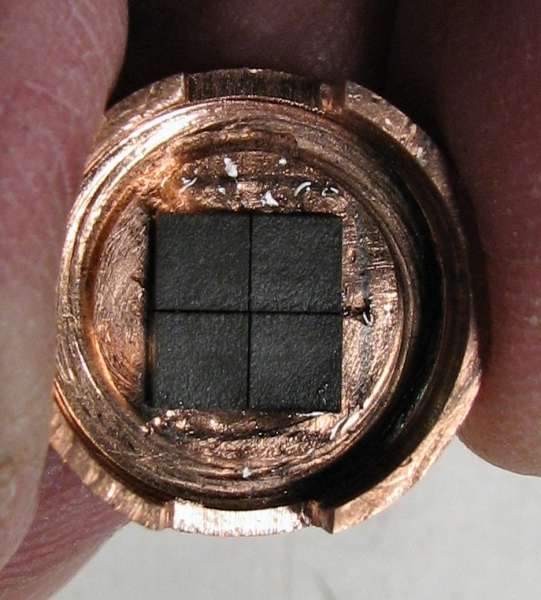
Here's the QTC material in the end cap. I used 4 pieces of it. I ran a very fine hairline of epoxy in the center, then set the QTC in and ran a line on two edges, just to hold the QTC in place. I just used a tiny bit of Epoxy.

7a

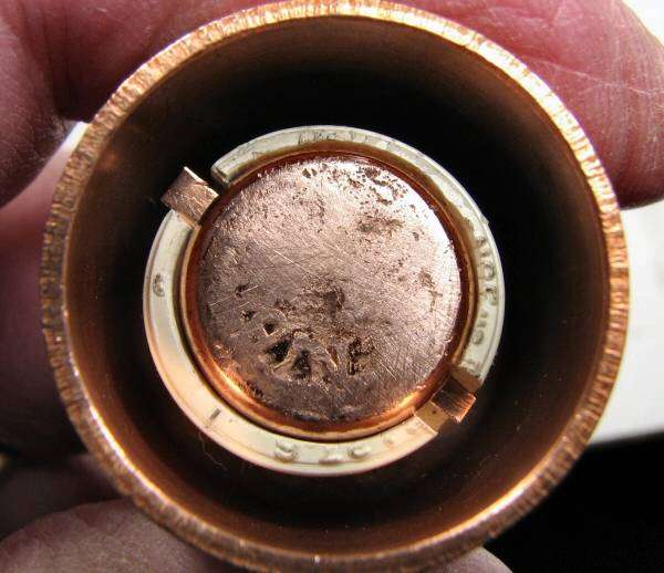
Here's the switch completed.

8a

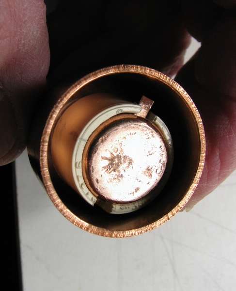
Here's the broken switch. My thoughts are written below.

9a

As I stated eariler, in a previous post, the QTC needs quite a bit of pressure to compress. What I found with this switch confirms that it would need at least 10 to 15 foot pounds of force to compress the QTC to form a 100% continuity contact.

The switch gave way after 3 tries of using it. The force made the PVC come off the upper copper ring.

I did get to use my meter and check ohms as I used the switch. Before turning the knob to make the contacts touch, I had a completely open circuit. As the top contact came down to touch the QTC, the meter jumped quite suddenly and each sucessive motion to compress it was totally erratic on the meter.

I did all of this with very fine adjustments of the knob and then reading the meter for a short time to see if the output was stable after each movement. The meter jumps all over the place once the contacts start compressing the QTC. Of course that can be from the switch slowly coming apart, but I was in a position to watch the switch body and I think the PVC (which was epoxied). gave out all at once, but maybe not. Even with just slight pressure on the QTC, the meter was all over the place, but my short lived test may be nothing but smoke and mirrors.

Even with no movement in the switch, the resistance jumps all over, once the QTC starts to compress. I also was able to prove out that I can compress the QTC to a certain point and then if the contacts touch each other at the end of the stroke, the circuit was 100% complete, so that's the way to have a defined High setting. Also I found that by not letting the contacts twist on the QTC, when compressing the QTC, it stayed in place like it should without damage to it. (again, the short lived test probably means nothing).

So, I'm through with QTC. If I had a lathe and a drill press, I would be making QTC switches. What I see is that a very small switch can be made. Much smaller than mine. A 10-32 bolt is plenty of size and a 1/4" shaft would work, but......

It has to be much stronger. It would have to be a "one piece body" where the bolt and contacts all fit inside the body, so that it could take the pressure. The bolt would need to be harder than a hardware store bolt. The knob would need to be metal and pinned to the bolt.

Without machining capabilities, I do not feel anyone will be able to make a reliable switch.

Justin

Justin,

Wonderful write-up and great photos to go along with everything. I understand the extra work involved documenting a build, and I have to say thanks! It's definately appreciated.

You've come up with a novel approach to QTC implementation. Unfortunately though, you seem to have found similar results to myself and others, which is erratic operation. This can be reduced via a fine thread twist compression, but then there's still no good repeatability.

I'm not sure where else to go with these...but I think you've taken it a step closer.

Why didn’t you just stack them together? Greater depth, more room for accuracy.

Thanks for that, Old-Lumens. I think it's an old rule of science that failed experiments can teach us as much as successful ones. I know you've said "never again", but I'm kinda looking forward to your next version.

Leelou, stacking would be tough, as this stuff is tiny (O-L's pix are so awesome it looks huge) and squirmy. (I think it's mostly silicone.) You'd somehow need a box for it that compresses under pressure but is still rigid enough to hold everything in.

Instead of a box how about a steel cylinder which can be easily fabricated. Cut the QTC pills to size and put them in. Problem is getting to zero resistance is virtually impossible but at least it may work. I’m just thinking out loud here so feel free to shoot this idea down.

In hobbies like this, each individual idea may be the newest breakthrough. I don’t think anyone has to be shot down, but merely guided.

There may be a way to use steel. I think it will depend on each individual setup. For me, I was going to make a copper light using an XM-L and 3 C NiMH, so the copper cap switch was essential to the particular build. However, I could see making a steel one for many other lights, but keeping it in place, in a tailcap would require threading and a lathe. I know from experience that a guy with a lathe, drill press and grinder could make a viable switch easily. If I had those tools I would have one done already and I would also have something made as a retrofit for "clicky" switches and Mag switches and I would be making money at this.

As far as stacking the QTC, in a word, No. It has a property similar to a pencil lead. Glue does not work on it and if two pieces are on top of each other, they slide. The best solution is to get hold of an uncut sheet of this stuff and then it could be "cut to fit" the area we want it in. Layers of it will make the fluctuations worse and flickering of the light would be worse.

In the long run, even though potentiometers create heat, they are still the most viable solution that I can see, for a dimmer switch in a flashlight. It's just that they usually take up too much room, use too much power and cause too much heat. Other than that, they are great.Undecided

Match, thank you for the kind words, I appreciate that.

I think with the aid of proper tools, the switch is viable.

If QTC were purchased in sheet form, where the user could cut the material to fit exactly in the "cup" they were using, then there would be no need for it moving.

I agree fine thread is the answer and I don't know if repeatability is absolutely necessary. I think if it simply could be twisted to where the user liked the output, that would be good enough.

Hopefully someone with the tools will want to pursue it.