Is there a thread dedicated to convoy s2 modding? I’ll like to try my hand at it. I’ve never nodded before and would like to read up on it. I also don’t know what the different styles of s2+ there are. I’m looking at buying one of BG and there’s a lot of options to hat i don’t understand.
https://m.banggood.com/Convoy-S2-Aluminum-Alloy-XM-L2-7135x8-LED-Flashlight-p-954829.html?utm_source=google&utm_medium=cpc_ods&utm_content=felix&utm_campaign=ods-sdsrm-camping&gclid=EAIaIQobChMI48LV2sD53AIV1VqGCh2ixgLvEAAYASAAEgLs7fD_BwE
Here is a link to the official seller and maker of Convoy flashlights in general, linking to the Convoy S2+:
https://www.aliexpress.com/store/product/desert-tan-S2-flashlight-with-XPL-HI-led-inside-and-ar-coated-glass-biscotti-firmware/330416_32820745681.html?spm=2114.12010612.8148356.2.7cd46d6cESBQCH
1- The Emitting Color. This amounts to the type of light the LED releases. V2 1A is akin to 6500k color temperature, like most LED car headlights. U6 3A is like the noon sun at 5000k, the closest you can get to sunlight.
U6 4C is like the afternoon sun at 4300-4500k. U3 7A is like the evening sun and incandescent lights at 3000k.
As a beginner, I would take the U6 4C or the U6 3A. Both are very pleasing tints, and I personally prefer the 4300-4500k of the U6 4C, since it looks the most natural.
2- The number of 7135 chips dictates the amount of current which passes through the LED. The more chips you have, the more current can pass, the more light is produced.
However, higher current means more heat, less efficiency, and a higher chance for the light to get hot. With the Convoy S2+, the max I would be comfortable with is 6x7135.
3- The UI. Just search for the Biscotti UI in the product page and choose this one.
I found this thread informative if you want to start with triple Convoy S2+ Triple as there are builds/links from other people.
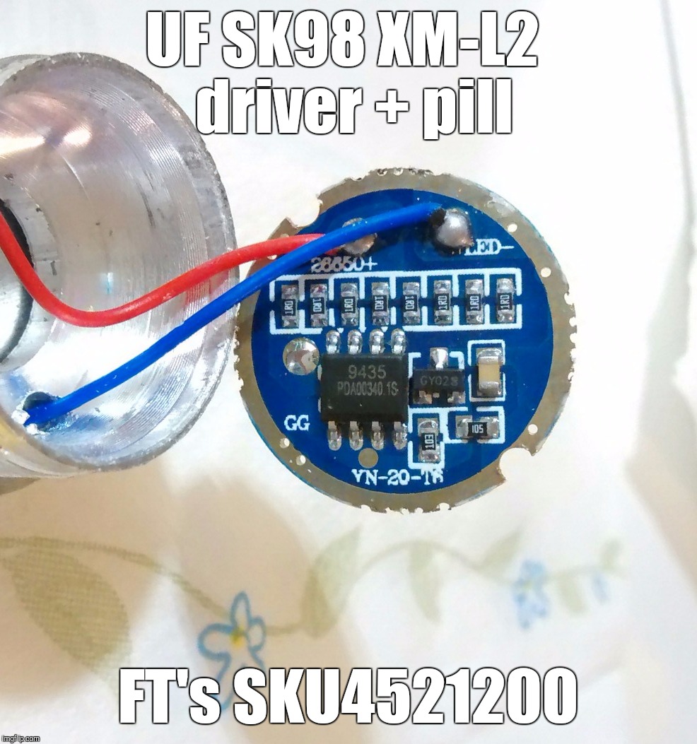
I wholeheartedly recommend this 3000mA regulated MOSFET driver: onboard AON7520 MOSFET (50A rating and ludicrously low RDS(ON) (max 3.1mΩ even at low VGS), in series with a 10mΩ current sense resistor (that is just 30mV sense voltage. This theoretically guarantees less than 50mV total voltage drop at the MOSFET + sense pair, this means dissipated heat in the driver stays below ½W even at 9A drive current (could be achieved stacking two R010 sense resistors atop the onboard one).
Just tested its PWM frequency with the VISO Flicker Tester: ≈334.3µs period this means ƒ = 1 / 0.0003433s = ≈2912.9Hz… ![]() Calibration was wrong! See below.
Calibration was wrong! See below.
Well, for me that is no problem.
Cheers ^:)
Originally posted on Mon, 08/20/2018 - 04:57. Lil fixup.
I’ll link a post I did with “mini” S2+ moded into triples:
It was inspired in many many posts and threads,and mods, done before!
Hope it helps! :+1:
Update for my above suggested driver. Took a more careful measurement with the torch output very close to the camera lens, having properly calibrated the app with an incandescent light source whose line frequency is 50Hz (100Hz flicker). This time I consistently obtained a 10.13µs period figure, which is 98716.68Hz, ≈98.7KHz.
I am waiting for HKJ to confirm this figure. In the meantime, you can start throwing out those crappy 7135 drivers where they belong:

![]()
Originally posted on Mon, 08/20/2018 - 14:55. Edited for a fix.
Is that a sense resistor, or is it just a ballast/current-limiting resistor?
Not current output tested, honestly. It wouldn't have any sense to call it “3000mA 3-Mode LED Flashlight Driver Circuit Board” while it not being regulated, though. Output remains fairly constant until battery voltage is under its corresponding minimum voltage treshold, this to me means it's regulated. Stock works hot but good in S2/S2+ torches. ![]()
:-)
Can someone explain what the differences between a ‘normal’ resistor and a current sense resistor are? And how drivers are ‘tricked’ to give more Amps to the emitter, if you stack resistors for lowering resistance, how to find these current-sense resistors on a board and how to calculate the values for modding.
Yeah, good to see more FET based linear drivers appearing.
A ballast or limiting resistor generally is one or more resistors in parallel meant to limit emitter current by dropping voltage over them. They are placed in series with the emitter, generally with a MOSFET to switch on/off the current path. Usually found in cheap drivers. Examples:

The above driver is boost plus small MOSFET with ballast (mode of operation when voltage is high enough). The R120 above is a single ballast or current limiting resistor.
Current sense resistors are monitorized by a microcontroller unit via a current sense amplifier which may be provided/handled by modern buck and/or boost integrated circuits instead of some separate chip to the microcontroller. Take this with a grain of salt, please, I'm not a designer of these circuits.
A current sense resistor is generally placed right in series with one of the emitter terminals, be it the negative (low side sensing) or the positive (high side sensing). The sense voltage can be accurately determined by Ohm's law: V = I / R. This sense voltage, after amplification, is compared to a reference value which allows the microcontroller unit to raise or lower the output voltage in order to accurately tune the output current. Since sense voltage remains constant, a lesser resistance sense resistor means higher output current (I = V / R). Examples:
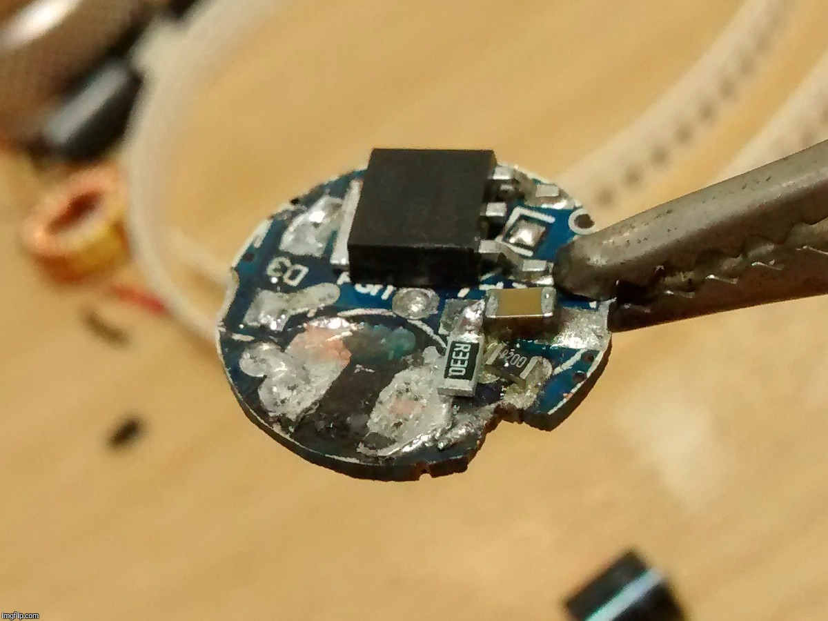
This is an old driver once tested by HKJ. Uses three R200s, one above and two below (0.2V sense voltage, this is quite gross imho). You can see I am sort of stacking another R330 in the photograph.
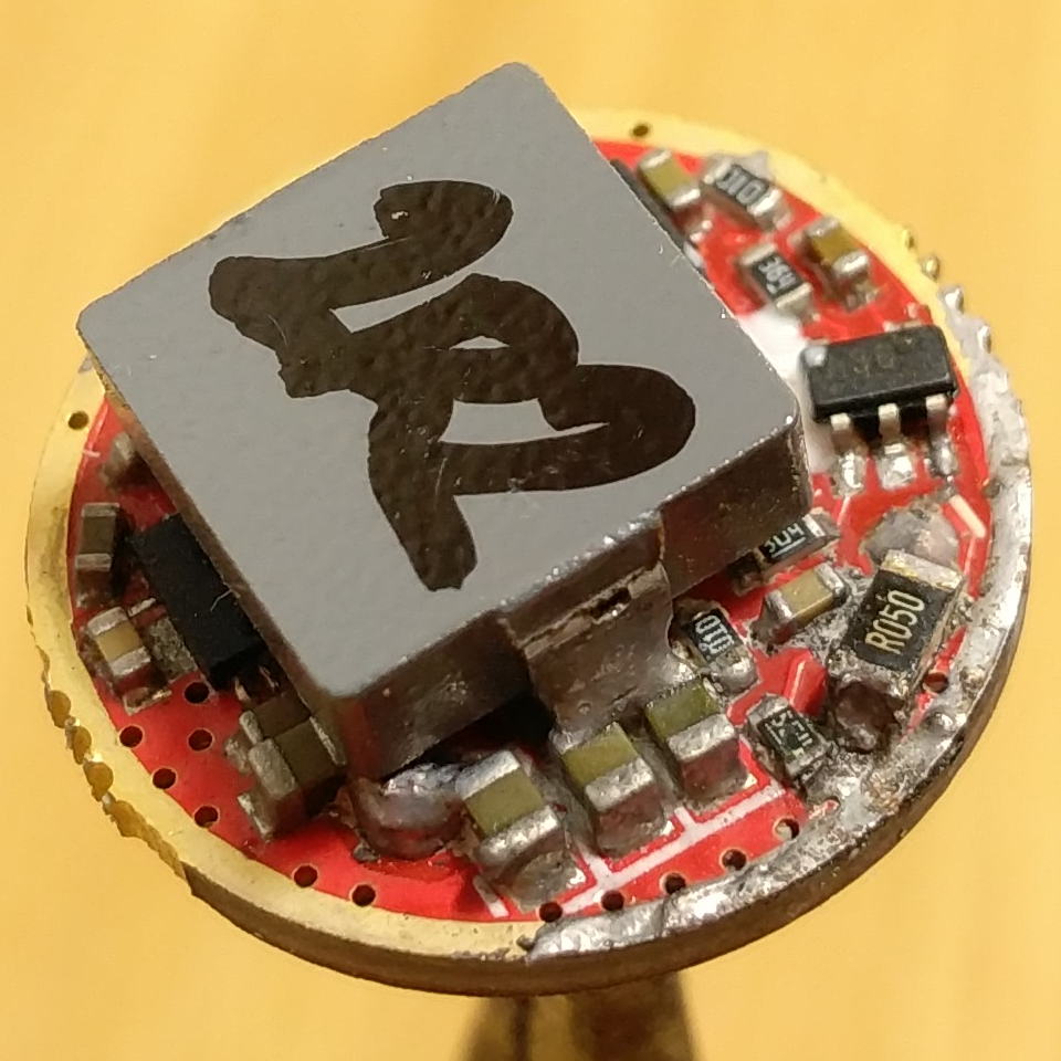
This is Kaidomain's H1-A with an R050 stacked over its default R025 for up to 4.5A at the emitter, which is about the maximum current that driver can handle (boost IC input limit: 10A).
^:)