I was thinking about doing one of those DX 5*cree empty drop-ins and getting some warm white XR-E emitters, just to play around with warm white. My problem is how to do it right. I know how to do it wrong and that would be to put them in parallel, so that the voltage would be close enough to use 3 "D" cell NiMH batteries, (that's what I am working on, is 3 D cell Nimh - 3.6vdc). I could do it that way, but everything I have ever read is that parallel is a big No No. One emitter goes out and they all go poof. All six would have to be matched, and that's not going to happen coming from China.
I know that series is the right way, but that would bump the voltage up to about 18vdc. I can't do that, so...
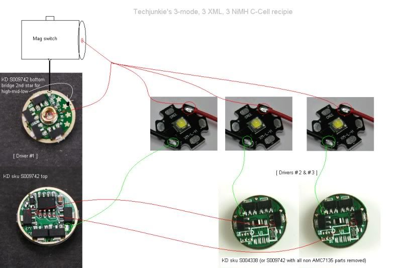
I see the threads from TechJunkie and dorpmuller using slave boards, but isn't that still parallel and not really a dependable way? I just don't have the technical knowledge on circuitry.
It's not parallel because of the way LED negative is wired. Note that LED- is wired off each board. So each LED will get 2800ma, assuming you're using the 8X7135 board.
I guess I still don't get it. The positive side is wired in parallel, so if one LED gets toasted, the rest will draw higher voltage immediately. In fact if they are not balanced, the ones with less resistance will automatically get higher voltage. Amperage is controlled by the boards, but voltage is basically uncontrolled. Is that incorrect? Am I looking at that in the wrong way? I'm not as concerned about amperage as I would be voltage. All I ever do is Direct Drive and if you control the voltage, the amperage takes care of itself because of the LED itself, but if you don't control the voltage, then Poof! ?
I am not an electronics guy and that is the problem, so I ask and I ask again and it may seem painful to others, but I need to know for sure before I go and spend money on something that will not be reliable and long lived.
I am not saying you are wrong, as I don't know. I am just asking for details on how it would keep from killing all the LEDs if one of them were to go out.
Circuit boards limit the current and the LEDs forward voltage at that current keeps the voltage stable. But I don’t think 3xNiMh setup can give such an high current.
6 XR-E @ 1 amp each would be 6 amps. D NiMHs do about 10 amps. I figured it would work. Vf limits to the point that the LED will not light till whatever the Low Vf is at, but the LED will take higher voltage, as you can fry any one of them, just by raising the voltage.
Now, you are saying that the circuit board, by limiting the amperage, automatically controls the voltage, because if the amperage is a set amount, the LED cannot get too many volts. I suppose there is a law about that. Wish I had taken more than basic math is school...
Ok, so let me ask another question. If I use the boards, one for dimming control, and the others as slaves, does that mean that 1 board will be powering itself as well as 4 other boards? Isn’t that a lot for the one host board? How much power can the little PWM chip take? Will it get excessively hot?
Someone got a flashlight, I’m totally in the dark now.
You said that the LED gets power on the negative side and that comes from the board. The boards (if I have 5 of them), 4 of them can only get power from the first board. If I have 4 boards asking for 2800mah each, how do they get that 2800mah? If the first board is only putting out 2800mah, how does it give out 2800mah X4 = 11200mah. It can't put out more than 2800mah, so where does the power come from? If it is supplying the other 4 boards, logic would tell me that the increased power flow would heat up the first board. According to the drawing, the first board is sending 2800mah thru the 7135 "PWM leg" to the others, is that incorrect? What am I missing here?
The connections for power on each board can be considered a pass-through. You are using a single mode controller to send the same signal to five power sources: one on the same PCB as the controller, four in linked boards.
Sorry for being argumentative. In the picture, the main board is one of the 5 mode 7135’s and the ATNEL PWM controller is being used to control “modes” on all other boards. To me the photo is just stacking. The other boards have all the components stripped off except the 7135s. This would equal a total of (if 8 each for my application), 32 of the 7135s stacked together. Even though the boards are seperate, it’s still 32 -7135s being fed from one PWM controller. I think that’s unsafe, but of course I’m only using common sense, not electronics knowledge. Kind of like plugging all my appliances into one 110v plug and letting 'er rip.
I understand the risk of parallel driving with no driver, but as you say, the only way to do it in series is with 18V. I have one of those builds using 6 x 14500 direct driving 6 x XRE using the taskled D2flex. It's nice set up but with short runtime.
I had a bunch of XRE's lying around from various mods and I built a Mag3D triple XRE wired in parallel and directly driven off 3D cells. I tried to match the Vf of all three LEDs to avoid blowing one/all. It came out much better than I expected, and I estimated it at ~600 OTF lumens. It pulled close to 3A with a predicted runtime of 3+ hours on 10,000 mAh NiMh cells. If I had used warm tinted Crees, it would have been beautiful.