While working on my entry for the 6th Annual Old Lumens Scratch Made Contest, I was looking for a PCB house that would do white solder mask, and do it on the cheap. I found PCBWay, which is one of the many Chinese places.
CliffNotes version: decent quality, great pricing for large PCBs or medium-high volume (due to shipping costs)
I placed an order for my Flip Lantern PCBs and a few illuminated tailcap boards. I was very pleased with the results. Perhaps not quite to the level of OshPark (I didn’t opt for ENIG), but a great value. Considering Oshpark wanted $18 for 3 of my Flip Lantern boards, while I could get 10 for $5 plus shipping from PCBWay. I opted for DHL shipping ($16), but ePacket was also available for $5. From the time that I submitted my order until they showed up at my house was 6 days (Wed -> Tues).
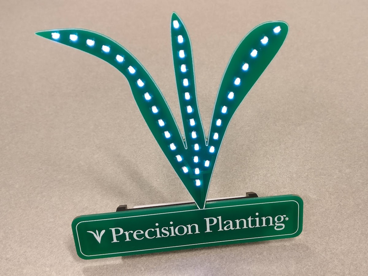
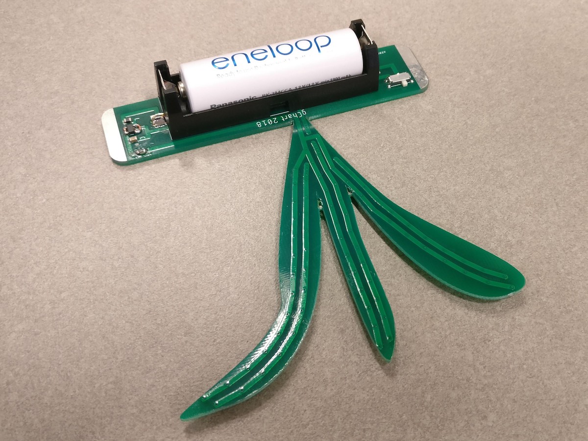
I had a good enough experience that I went ahead and made something bigger (~98mm x 95mm) just for fun: my company’s logo with a boost circuit and some LEDs. Getting this from OshPark would have cost $67 for 3, but once again I got 10 for $5 (anything smaller that 100mm x 100mm is 10 for $5). While I was at it, I submitted a couple new designs for tailcap boards (some 17x17 and some 19x19). Instead of sending me 10 of each, I actually got 15 of one and 17 of the other! And my order came in just 5 days (Fri -> Wed).
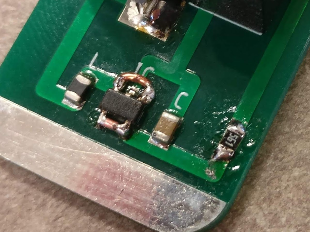
Yeah… I rushed and made two big, but correctable, mistakes: I forgot the resistor pads and I messed up the IC pinout :person_facepalming:
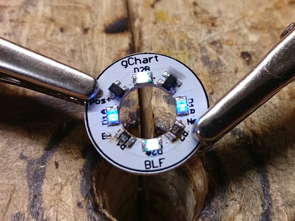
And here’s a sneak peak of those new designs… any guesses on what you see?
Well, my (basic) adjustable voltage supply came in today so I could test my new creation: a constant current tailcap with low voltage protection.
While not an entirely new idea, this only needs two components more than usual. Both are cheap (about $0.40 each) and readily available.
In the video I mentioned quiescent current of 2.8 picoamps. What I meant was 2.8uA. Oops. And it’s a total of 3.3uA while on, going down to 0.5uA after LVP trips.
Haha! Picoamps… I have no idea where I pulled that from. That’s what I get for trying to rush a quick video while the wife thinks I’m taking the trash out
Nice! I’ll have to remember PCBWay if I ever get back into designing boards. I have a few ideas that will definitely benefit from the lower pricing compared to OSH Park. And a couple other things that I’ve started way back and never finished.
EDIT: Wait, did you say Constant Current and LVP in a lighted tail switch PCB? You’re almost to the point that you don’t even need a flashlight any more. Strap that thing onto a large button cell, and you have a VERY fancy throwy! (do you guys remember those fun little things?)
Oh! You know what would be cool? Make an “infinitely variable” light by just putting the QTC across two pads on a PCB, in place of a side switch. The harder you press, the brighter the light gets!
Well, thanks for expanding my horizons. I’d never heard of QTC before (for those interested in reading up, I found that it’s “Quantum Tunneling Composite”). Interesting stuff.
I’ve actually been thinking about using bi-color LEDs, multiple LEDs, flashing LEDs, etc as a low voltage indicator. It would require a little more circuitry, but definitely do-able. Though for color changing, I’d likely do blue>red as I’m red-green colorblind and there’s green>red power indicators everywhere and it drives me nuts.
Another thought I had was to have 6 or so LEDs on the tailcap and have them turn off one-by-one as the cell depletes. Kinda like a 6-segment voltage indicator wrapped around the switch. My only concern is that my OCD tendencies might go crazy at having a partially-lit tailcap.
I’ve been using Eagle. I’ve heard people talk about KiCad, but haven’t tried it yet.
That build is pretty sweet, CRX (as they all are!). Interesting design with the interchangeable tail pieces. Any shots on that QTC pill? I’m curious what that looks like.
Even with the changes to Eagle in the past couple years making it much less intuitive and easy to use, it’s still MUCH better than Ki-CAD, if only for our drivers, because some of our commonly used driver components don’t have libraries in KiCAD and it’s not as easy to make new libraries in KiCAD as it is in Eagle. One advantage to KiCAD is it’s free as in freedom. It will never be proprietary, and if development ever moves in a direction people don’t like, someone can legally fork it and make it right again. I want to learn to use it, but the learning curve to make new libraries is what’s holding me back right now. There are a couple of new conversion tools for Eagle to KiCAD, but they aren’t super easy to figure out either. :person_facepalming: