Anyone have idea how to reflow those junk leds and replace with XM-L2 and not damage electronic?
I’m used on iron to do single led reflow, but it would harm the electronics.
Actualy I don’t have those PCB’s at hand. I’m just preparing myself to get ready when it comes.
It’s cheapo motobike light that is supposed to have such design.
I’m guessing that is a triac which basically chops AC.
I’ve used one of those craft guns without adjusting the heat. I used some pieces of aluminum foil tape (actual duct tape) to mask off the rest of the pcb (wrapping onto the backside to protect from heat and physical disruption in case the solder melted under other components. I think I also fluxed the whole board to protect the other solder joints from oxidation.
I was working on a blown $10 driver though, so I was out nothing if I failed.
I have done two lights with six led’s, a boost controller and a mcu, both are working fine. Your board has a lot less components, reflowing the two led’s should be fine. Try to have everything ready so you only have to heat the board once.
Underneath the thermal pad of the led’s there is likely a lot of vias to transfer the heat to a fairly large ground plane. The ground plane carries the heat to the light’s casing. And when you try soldering it also spreads the heat across the whole board.
Its going to take a lot of heat, once the first one comes free the second one won’t be far away. Best to preheat the whole board with a heat gun. Use a big soldering iron with fresh solder on the tip and put it on the vias under one led. If there is any chance of the board shaking take the inductor off first. It’s better to place it on the bench than watch it bounce off the floor. The smaller stuff should stay in place.
There doesn’t appear to be much filtering on the board, and you’re probably going to modify the sense resistors. Cranking up the current will make more electrical noise and might make the buck controller unstable. This would be a good time to add a small ceramic capacitor in parallel with the big electrolytic capacitor to trim some noise off.
@eas, thanks for the idea of alu foil which will cool down the rest. Using Kapton tape would be probably good to use just near the leds when using heat gun.
@WTF, thanks fo suggestions. I was thinking to use an old but quite powerful solder iron and made contact just below the led. Only if I would not suceeed with heat gun. Will do some tests before on cheapo triple led PCB I’ve got in a drawer.
About modding - I think I can recognize two sense resistors near black wire. Will see what are diodes used. Good point - I have few bigger SMD capacitors (maybe tantalum 100uF 50V, need to take a look) and will add in paralell to C2 or even replace existing.
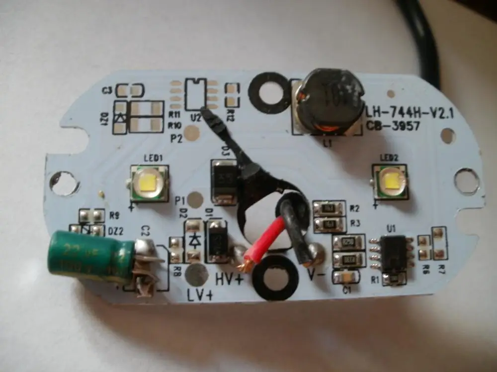
It happened that driver I’ve got is bit different. I’ve made some pictures and try to mark connections between elements. On the first picture there are not all of them. On the second I’ve tired to follow the flow through leds. Third is showing part around some strange IC. Really don’t know the purpose of it since there are no modes in this light.
SMD diodes are marked SS26. Empty slots are in parallel. Funny there is reverse path or something over big capacitor.
Detail around IC
What I want is to replace leds to geniue Cree XM-L2 and raise current to them as housing is big enouh that can easily stand 30W of power.
Can someone help with ideas what to do?
That IC is probably a buck controller with an internal fet for switching the inductor on and off. Not sure what the resistor marked 472 is used for, maybe setting a voltage limit or the fet off time.
It would be nice to have the data sheet for the buck controller but googling those numbers didn’t get to far. It looks like the board is set up for more power. That Schottky diode is only rated for two amps, so paralleling both of them would be a good place to start. Then start dropping the resistance on the sense resistor. The inductor looks small so keep checking it for overheating. The buck chip probably has overtemp protection built in.
Everything on that board is pretty replaceable except for the buck converter, unless you can find it on aliexpress I would not try pushing it to 30 watts. There’s a 20w in the part number on the board, maybe it means watts.
WTF, thank you. Yes it means 20W power. Here is link to Ali -> Link
Light is declared as 20W with 10V-30V input, but the housing is very big, specialy compared to bicycle lights.
Regarding diode SS26, does it means max 2A current can flow through it, everything above would be blocked or diode would blow? I only have SS54 at hand, maybe can find SS34 on some bicycle light driver. The question is, can I use one SS54 (or SS34) instead of two SS26 ?
Also I’m wondering what is meaning of the reverse path from inductor throught second SS26 over capacitor back to the first SS26 (actualy to the first led)? I’ve marked that path with red and added path from capacitor to the ground
Don’t know much about electronics, so my questions might be boring.
The reverse path is normal for a buck driver, Wikipedia explains it well. The buck controller turns the fet on sending current through the inductor and led’s. The inductor charges up and stores energy that opposes the initial current. When the fet turns off the inductor discharges (with reverse polarity) through the Schottky diode and the led’s. Then the fet turns back on and restarts the cycle.
There are a lot of voltage spikes when this happens. There are also a lot of voltage spikes from an engines alternator and ignition system. Also an engine with a 12v battery will have an alternator producing14.5v to charge the battery. The voltage rating of the components are higher because of this, the SS54’s might not last very long. SS26 by V+ can probably be replaced by a regular diode, and then moved beside the one by the inductor.
If you look up the data sheets on the diodes it will give you the voltage and current ratings as well as maximum junction temperature. The current rating is in average amps. The current through both diodes switches on and off. I’m no expert at this stuff but as long as the case temperature of the diode doesn’t get too hot you should be able to bump up the current through the led’s. The one by V+ will see the most current and run the hottest.
The led’s are not sitting on a mcpcb, its hard to say how hard they can be driven without overheating. It’s possible the diodes won’t be the limiter.
If you are going to try this, I suggest you first pre-heat the whole board up to say 150C. Perhaps in a fan oven. Then quickly have a go at the LEDs with whatever you have got, basic soldering iron, fancy hot air re-work station etc. It won’t take much to shift them, once pre-heated, and will be kinder to everything else.
Put the new LEDs on the same way, i.e. dabs of solder paste, place them, pre-heat in an oven, dry out the paste, then quickly blast them with hot air, even just a 100W halogen bulb focussed through a big magnifying glass.
I now just use a butane powered “iron” that blasts out hot air like you wouldn’t believe, from it’s catalytic converter, once you unscrew the soldering tip. And I suspect it delivers a mildly reducing atmosphere (some CO), which is desirable for soldering. Once you get the hang of it, it is a delicate, but also very powerful tool. But could also destroy things in seconds.
WTF, thanks for explanation. Now I’ve got it about inductor and reverse path.
I understand there is going to be a lot of spikes and you think SS54 or SS34 (40V) is to low in terms of voltage, right? Don’t have ordinary diodes at hand nor I know which ones to use.
So I’ll firstly try to measure current on the stock driver and then add current resistor. I’ve got some 1, 1.5, 2, 2.2 Ohms and below 1Ohm the ones with 0.500, 0,400, 0.330, 0.120, 0.100 Ohms. Since there is stock R150 I’m thinking I can add R500 for the first try. Are you agree?
Tom Tom, yes preheating would help a bit, thanks. I’ve already tested reflowing led on a single 20mm PCB using hot air gun. I think I could do it on this bigger PCB too. Will report it back when I come to that.
The 40v diodes could be fine but it only takes one spike to damage them. The input diode failing probably wouldn’t be a big deal but if the one by the inductor shorts when it fails it would destroy the buck controller chip.
Most times I assume the people who design this stuff and stand behind a thousand plus units sold know what they are doing and specify things for a reason. A lot of times a lower spec part will be fine but you have to be OK with the increased risk of something failing.
Chances are the SS26 diodes will be fine. You can’t push a lot of current through that little inductor and the small fet inside the buck controller will probably overheat if you try. If you have a really small thermocouple you can check temperatures and make sure things stay reasonable.
That R500 should increase current by 30% (0.115 ohm total). Once you get the current up to two amps it would be better to go in smaller steps. Have a look at Cree’s product characterization tool and see how far you want to push things.
WTF, I’m intending to push XM-L2 up to 3A, no more, maybe less. They are rated to 3A, so no problem should occur to them. In fact that would be all together up to 20W as the light is declared, but probably not really pushed that hard. Also don’t know where the excesive voltage goes ie. voltage not used by leds as the input is declared as 10-30V.
Will take care about other parts. With some bicycle lights even smaller inductors are runt at that currents up to 3A, but voltage is lower (max. 8.4V tipicaly) and comes from steady source ie. 2S battery pack. Will see what starting point is using 12V power adapter as a source and report it back.
On the other hand this whole PCB is mounted (screwed) to the big housing thus making quite good heatsink. I’ll use some better thermal paste and make shure it is sitting flat with no gaps (originaly it was not placed very well). So elements should have some sort of cooling. Of course it would be much better if the leds were separated.
the weak point is that Buck circuit I doubt the Inductor and parts like 3A
the bigger the voltage gap the more power loss on the diode,
the voltage is not a problem for the diode if you got proper output capacitor
a proper output cap would be MLCC 1206 or 12010 with 10V and 4.7uF
also adding input cap of 16V 1206 or 1210 with 10uF would be a good thing, those aluminum caps are not so good
Just measured power to the stock system. Running from 12V power adapter I’ve got only 9W of input (12.2V at 0.75A). I thought so it would not be declared 20W since the stock leds are low powered china fake XM-L like LatticeBright XM.
Lexel thank you for your input. I’ve got some Tantalum capacitors at hand.I think they are rated 16 and 25V (at least latest is 100uF if I can recall correctly). Not shure where to place them on that board. For input it is between V+ and V-, but for output don’t know. Is it instead of round alu capacitor or in parallel to it?
PS. Just added R500 in parallel to existing R150 and got 12.6W at input (12.2V at 1.03A). Runt it just to measure input power.
I haven’t seen the back side of the PCB, but f it’s nice and flat, you might as well put it on a nice flat surface that can heat up the whole thing. A skillet for example.
The parts will stay in place because of the solder adhesion.
It will be a lot easier to replace the LEDs when the whole thing is hot.