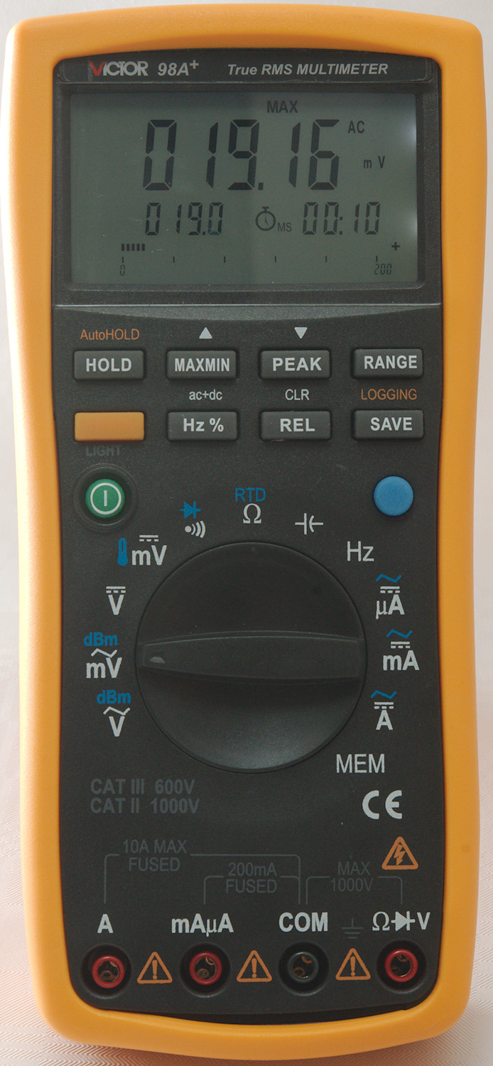
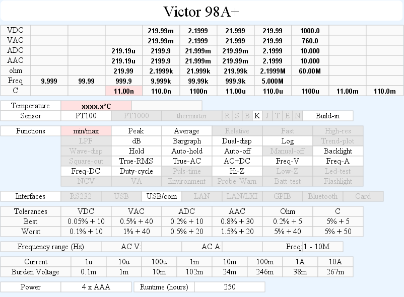
DMM Victor 98A+
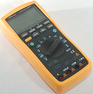
This is one of Victors better models (189W looks to be a more advanced model of the same meter).
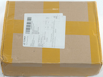
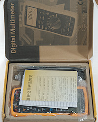
The box for the meter is a brown cardboard box, that is very practical for shipping.
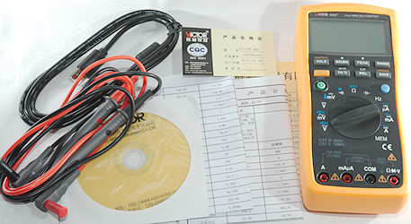
The box contained the meter, probes, a usb cable, a calibration certificate and a DVD with manual in Chinese and software.
It is possible to download a manual from Victor, but it do not match the meter.
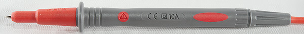
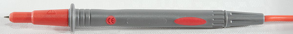
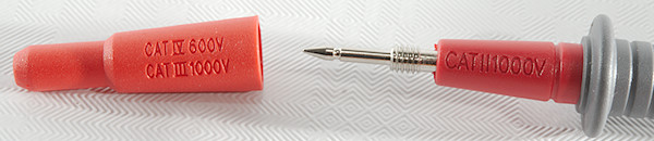
The probe is fairly standard with tip covers and the usual rating of CAT II 1000V without covers and CAT III 1000V / CAV IV 600V with covers.
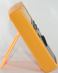
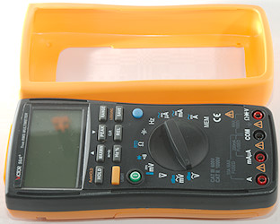
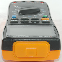
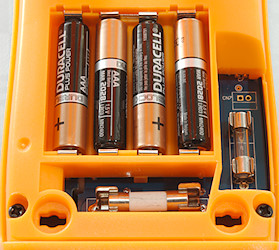
The meter is heavy enough to be standing while turning the range switch or pressing buttons.
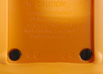
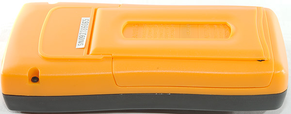
The two black “screws” are used to open the meter, but the sleeve must be removed first.
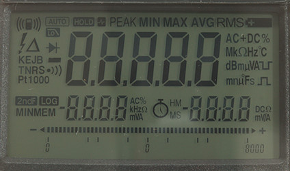
The calibration certificate is on multiple pages and show how well the meter matches the calibration reference.
Display
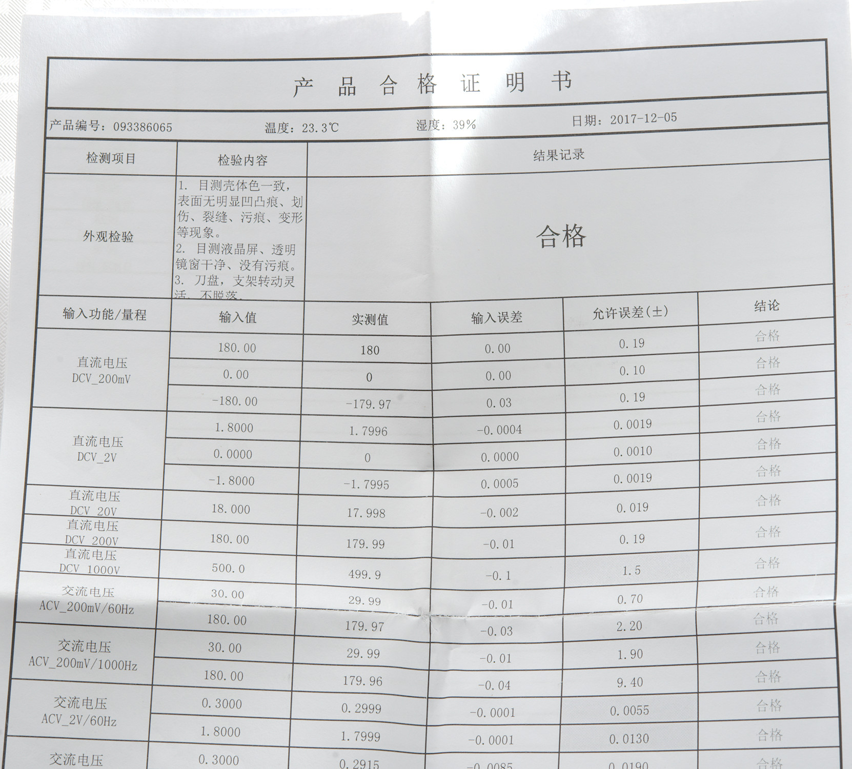
All the segments on the display, as usual not all of them are used.
The display has two secondary displays and a bargraph where it can show maximum range.
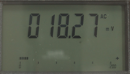
A typical measurement without extra function activated, the bargraph shows that the range is “200”.
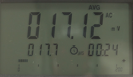
Activating max/min and selected average.
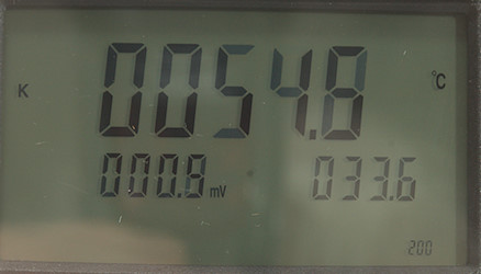
When measuring temperature the secondary display shows sensor value and reference temperature.
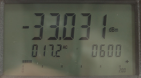
The dBm display
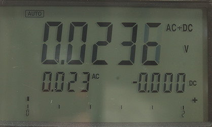
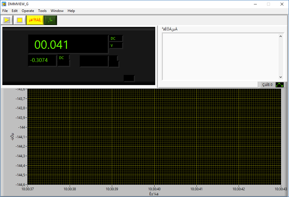
AC+DC is very nice with both AC and DC voltage displayed.
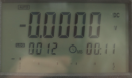
Logging mode, the meter will save a reading each second (It will also beep each second).
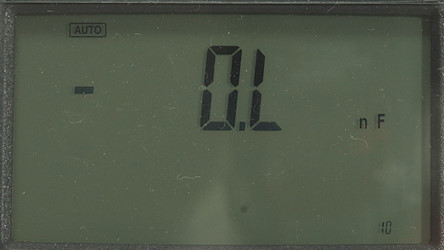
Capacitance mode, with no capacitor it shows OL, maybe due to a –0.1nF offset in the range. This prevents using the REL button to eliminate the offset.
Secondary display functions (After / is secondary values):
-
REL: relative or percent/absolute/reference
-
Auto-hold: Held value/Current value
-
dB: dBm/voltage/impedance
-
min/max: max/absolute/time since start of min/max
-
AC-frequency: Frequency/voltage or duty cycle (This is valid for both voltage and current)
-
Frequency: Frequency/duty-cycle
-
AC+DC: AC+DC/AC/DC (This is valid for both voltage and current)
-
Thermocoupler temperature: Temperature/sensor mV/reference temp
-
RTD Temperature: Temperature/sensor ohm
-
Logging mode: value/Record number/time
-
Save: value/Memory number
-
MEM: value/Memory number
Functions
Buttons:
-
Hold: Freeze the display. Using the yellow shift first activates auto-hold.
-
MaxMin: Activate min/max function, press to select average, hold down to deactivate. In mem this will increment memory no.
-
Peak: Activate peak capture, press to select minimum, hold down to deactivate. In mem this will decrement memory no.
-
Range: Select manual range and change manual range.
-
Yellow: Selected secondary function on HOLD and SAVE.
-
Hz %: Select frequency in AC modes and AC+DC in DC modes.
-
REL/CLR: Enable relative mode. In MEM this will clear SAVE or LOGGING memory.
-
SAVE/Logging: Save to SAVE memory, Using the yellow shift will start logging to LOGGING memory, but only if it is empty. In MEM this is used to enable viewing of LOGGING memory.
MaxMin/Peak/Rel will all select manual range.
Rotary switch:
-
VAC: Show AC voltage, frequency, duty cycle and dB
-
mVAC: Show AC millivoltage, frequency, duty cycle and dB
-
VDC: Show DC voltage, AC+DC, AC and DC.
-
mVDC: Show DC voltage, AC+DC, AC and DC. Thermocoupler temperature is also selected here.
-
 : Continuity and diode.
 -
 : Resistance and RTD temperature.
 -
 : Capacitance.
 -
uA: uA current DC, AC, frequency, duty cycle, AC+DC
-
mA: mA current DC, AC, frequency, duty cycle, AC+DC
-
A: A current DC, AC, frequency, duty cycle, AC+DC
-
MEM: View SAVE memory, press yellow shift and LOGGING to view LOGGING memory.
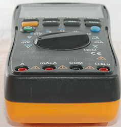
Input

-
A: High current
-
mAuA: The lower current ranges, the selector switch will change between two different shunts.
-
CON: The common terminal for all ranges.
-
xxx: All other ranges.
Measurements
-
Volt and frequency
-
At 1Vrms in AC frequency input range is from 15Hz to 10kHz (Higher voltage do not improve range)
-
At 1Vrms in frequency input range is from 3Hz to 5MHz (Higher voltage do not improve range)
-
At 1Vrms in frequency input the meter can handle a DC offset from –3V to at least +8V
-
Duty cycle works from 10% to 99% at 100kHz with 2Vpp in frequency input, precision is within 3.0
-
Duty cycle works from 10% to 99% at 10kHz with 2Vpp in frequency input, precision is within 0.2
-
Max/min changes between max/min?/average, the min? updates for each measurement and do not capture a value (It do not show minimum).
-
Max/min can be used on voltage AC/DC/AC+DC, ohm, temperature, frequency, current AC/DC
-
Max/min on VDC needs about 500ms to capture a voltage on DC with repeating pulses (min is not captured).
-
Peak changes between peak max and peak min, both works fine.
-
Peak can be used on voltage DC and current DC
-
Peak on VDC needs about 20ms to capture a voltage.
-
1 VAC on AC input is 5% down at 1.3kHz
-
1 VAC on DC+AC input is 5% down at 1.3kHz
-
In dBm the impedance is assumed to be 600ohm
-
Display will show high voltage symbol at 30VDC/VAC
-
Input impedance is 10…11Mohm on DC. AC and mVAC is a capacitor (Impedance is around 5Mohm).
-
mV DC range is high impedance up to around 2 volt where it slowly drops to 3kOhm
-
Hz input impedance is about 1Mohm up to around 12V where it drops to 2kOhm.
-
Over voltage protection is 1000VDC/750VAC
-
-
Current
-
220mA range has audible alarm at 200mA
-
10A range has audible alarm at 10A
-
uAmA current is protected by a 0.2A/250V 5*20mm fuse.
-
10A current is protected by a 10A/250V 6.2*24mm fuse (Holder will fit 6x30mm fuse).
-
-
Ohm, Continuity, diode and capacitance
-
Ohm needs about 5s to measure 100ohm
-
Ohm is 2.5V open and 0.8mA shorted
-
RTD is 2.3V open and 0.2mA shorted
-
Continuity beeps when resistance is below 50ohm.
-
Continuity is very fast (below 10ms).
-
Continuity is 0.8V open and 0.3mA shorted
-
Diode range uses 3.2V, max. display is 2.1999V at 0.2mA, max. current is 0.2mA shorted.
-
10uF takes about 5.5 seconds to measure.
-
70000uF takes about 28 seconds to measure when staring in nF range, 10 seconds in mF range.
-
No rated overload protection
-
-
Miscellaneous
-
Current consumption of meter is about 3mA to 4.5mA depending on range, 37mA with backlight.
-
Current consumption when off is about 3uA.
-
Meter works down to 2.4V where display is very faded, it turns off at 2.2V, battery symbol show at 4.0V.
-
Reading do not change with battery voltage.
-
Backlight is stable down to 3.3V, then it starts fading and is about off at 2.6V.
-
Internal temperature sensor is about 10°C off, this means a 10°C error on thermocoupler measurements.
-
Viewing angle is good.
-
Display updates around 2.5 times/sec
-
Display needs a couple of updates to show the correct value.
-
Bargraph updates faster than display.
-
Backlight turns off together with meter, not before.
-
Meter will automatic turn off after 10 minutes without any warning.
-
Standard probes cannot be fully seated.
-
Weight is 511g without accessories, but with sleeve and batteries.
-
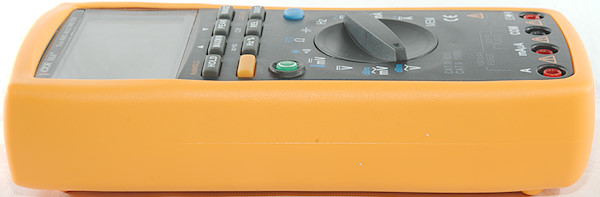
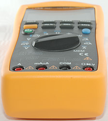
Size is 206 x 97 x 50mm.
-
-
Probes
-
Probe resistance 26mOhm for one.
-
Probe wire is soft and 100cm long.
-
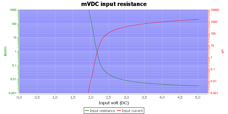
The input resistance in mVDC
Range switch is unreliable and may not always select same range as switch position.
Internal thermocoupler compensation sensor is 10°C wrong.
Capacitance has a 100pF offset in the lowest range and REL do not work because meter is in overload.
Min in min/max do not show minimum value.
Computer connection
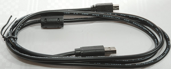
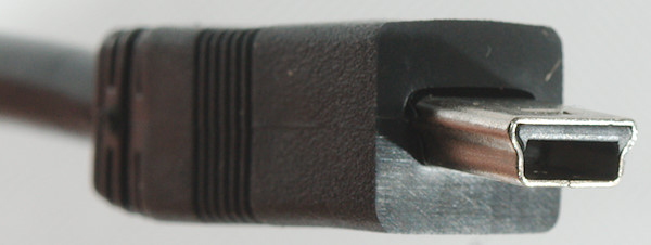
The meter included a USB cable with mini usb connector.
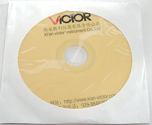
And a CD with the software on (The software is date 2017)

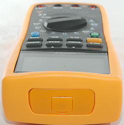
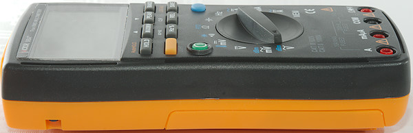
The meter has a mini usb connector behind a flap, this is good for environment protection.
It was difficult to install the software, it use Chinese file names and my windows could not handle them. Some renaming later I succeeded in getting it installation and started. It uses NI-VISA software.
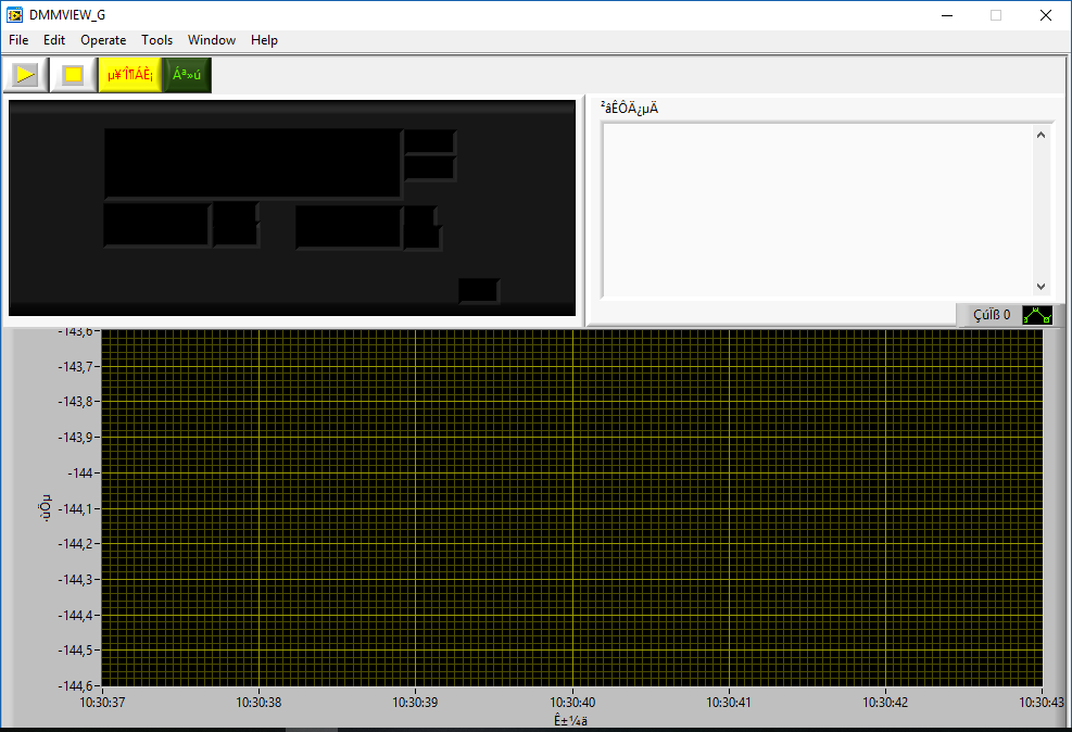
First windows was a bit depressing to look at.
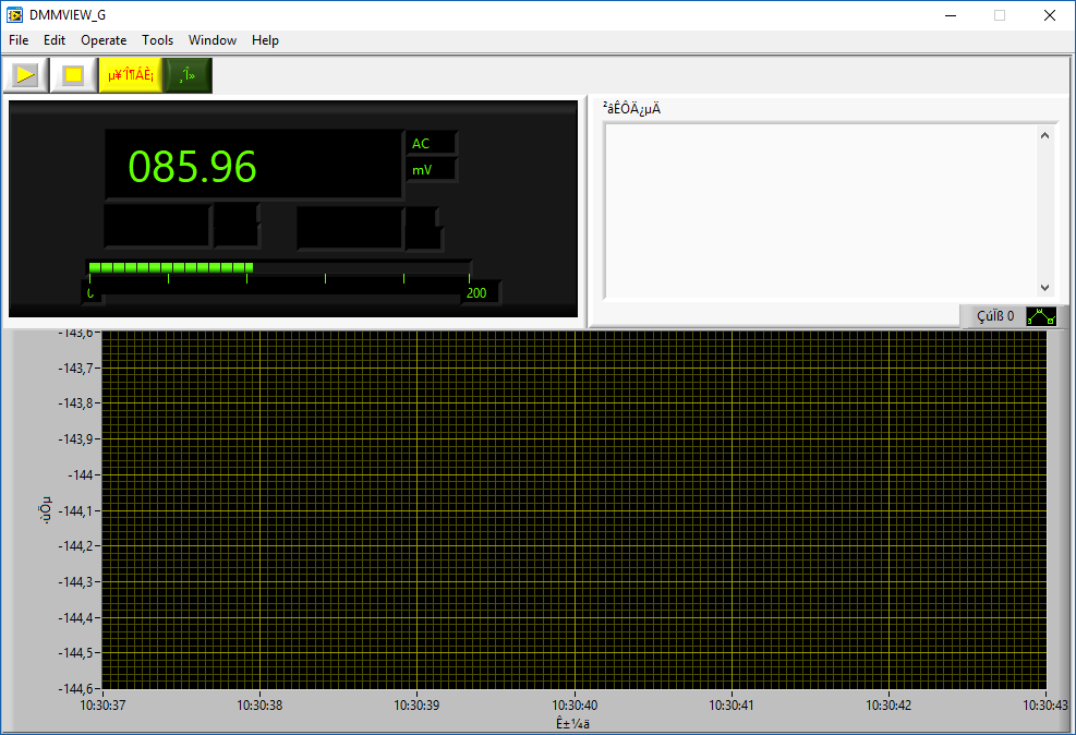
Pressing the button with the green letters reset the meter and starts reading data.
I did not get a chart or a table, only current values from meter.

Pressing the Hz button in AC mode shows 3 value, but not the same values as the meters display that only shows two vales.
Peak worked the same way, the screen shows peak max and peak min.
The software is not really usable on my machine (It will probably work better on a Chinese windows)
Tear down

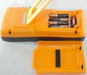
I had to remove the battery cover, then it was four screws to open the meter.

The back is fairly hard plastic and looks rather thin.

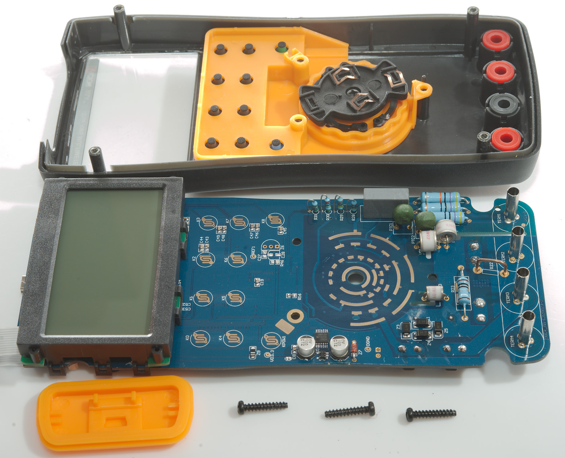
I had to remove 3 more screws to get the circuit board out.
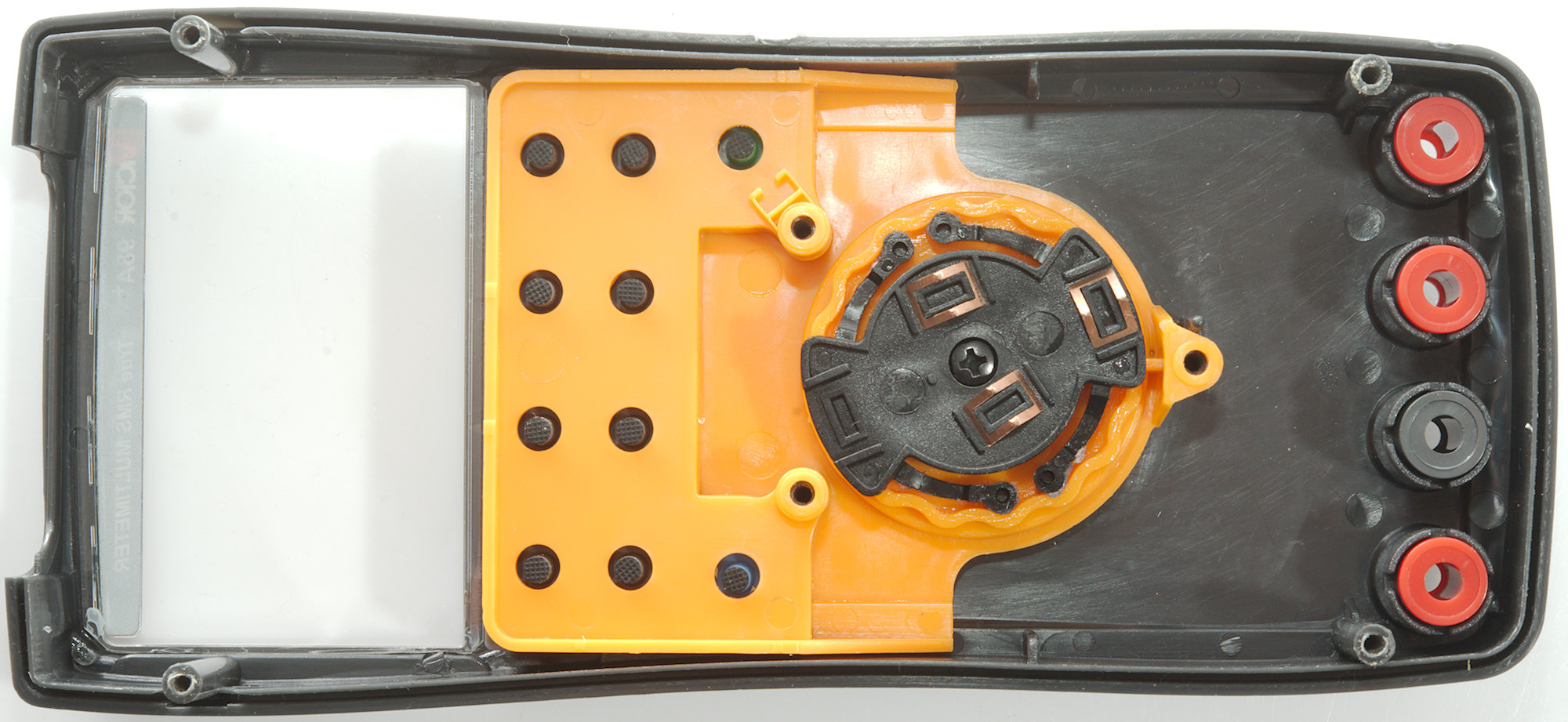
It looks like the switch assembly can be taken out, but it did not move easily and I let it stay in place (I probably had to remove the screw inside the switch).

The display assembly is clipped on and could be removed if disconnecting the display cable.
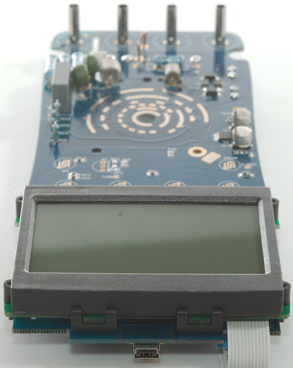
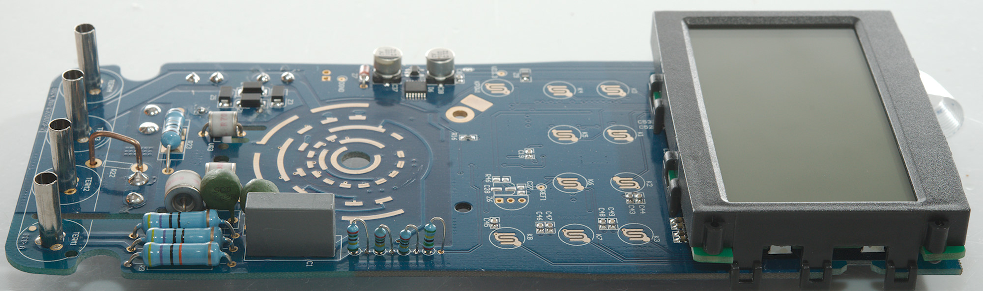
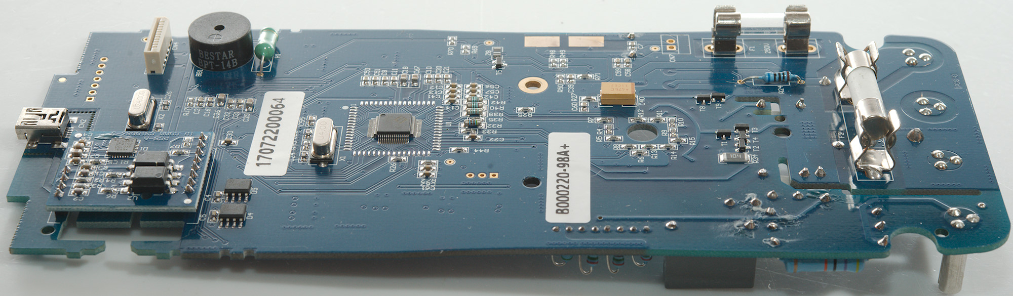
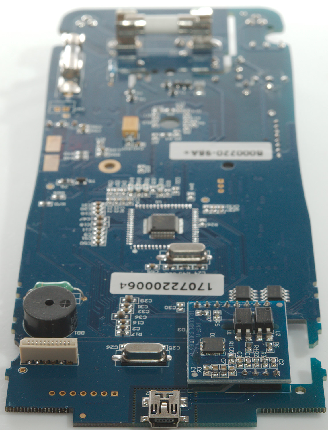
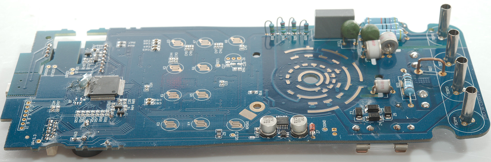
This side has the low volt input protection, i.e. transistor pairs: mVDC, temperature, continuity, diode, ohm, RTD, capacity (T1 & T3), Hz (T8 & T9), capacity (T2 & T4) after a 100kOhm (R34) resistor.
The uA current shunt (R24: 100ohm) is on this side.
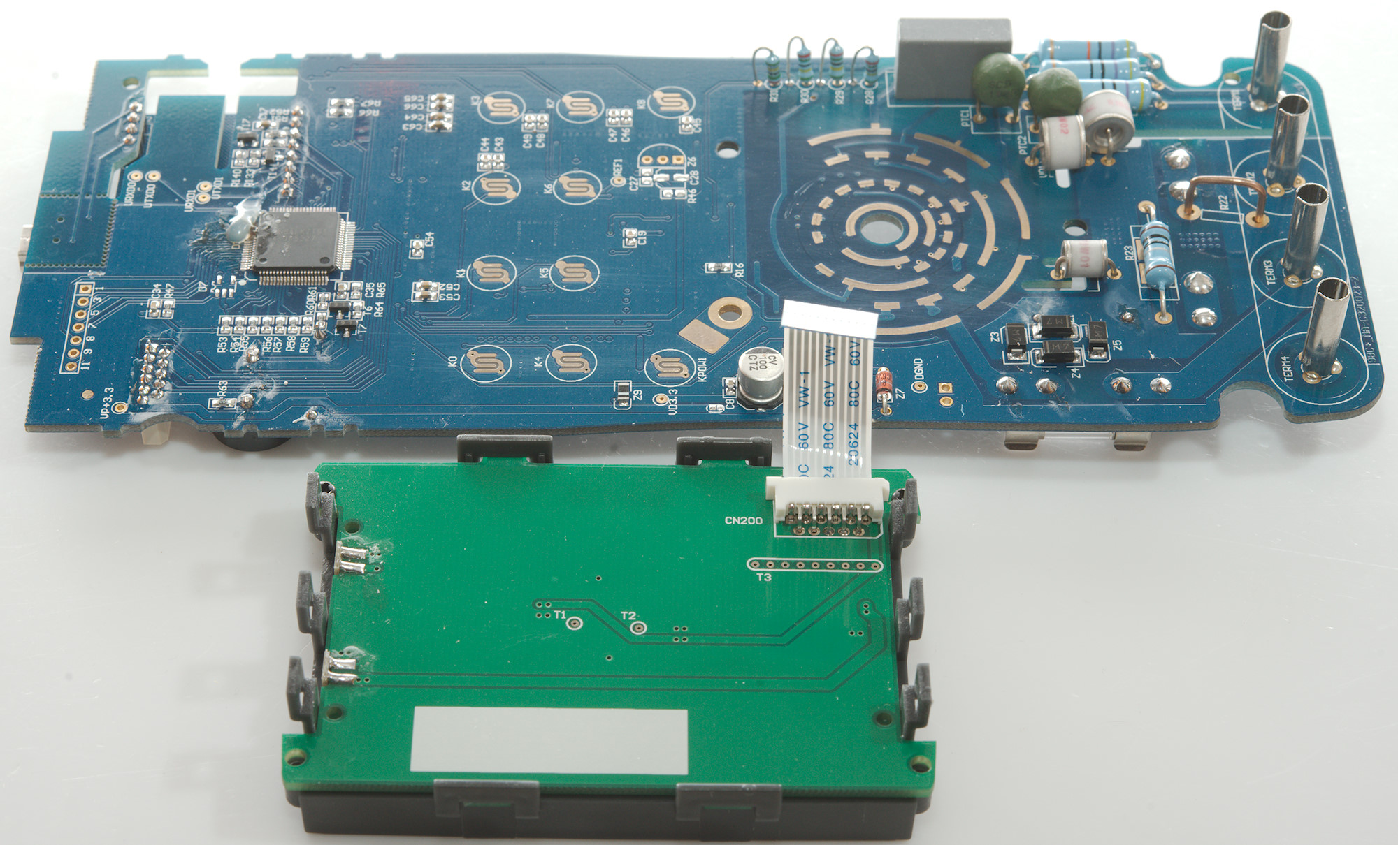
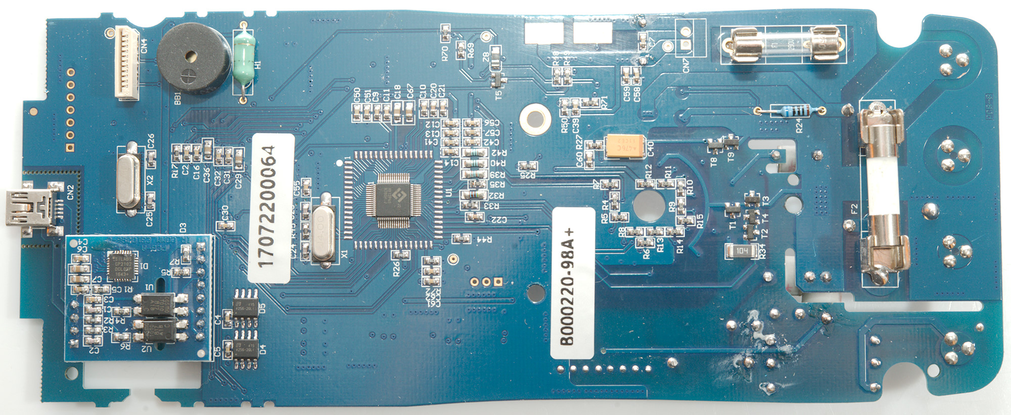
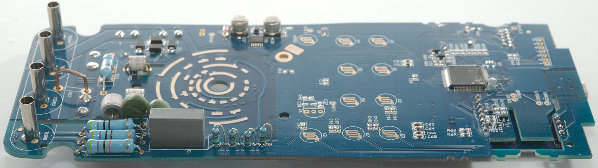
The main multimeter chip (U1: HY12P65 5000count). There is two memory chips (D4 & D5: Marked 4256-2GLI) for logging and other stuff. Above these chips is the USB interface on a separate board, it has two optocouplers (U1 & U2: Cosmo:K1010 5000V) and a standard USB interface chip (D1: CP2102)
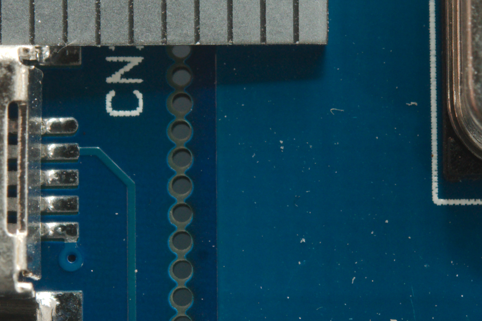
The optocoupler is fairly good, but how much safety distance are there? The ticks on the ruler is 1mm apart, this means from the usb track to the ground place is about 2.5mm, this is not very good.
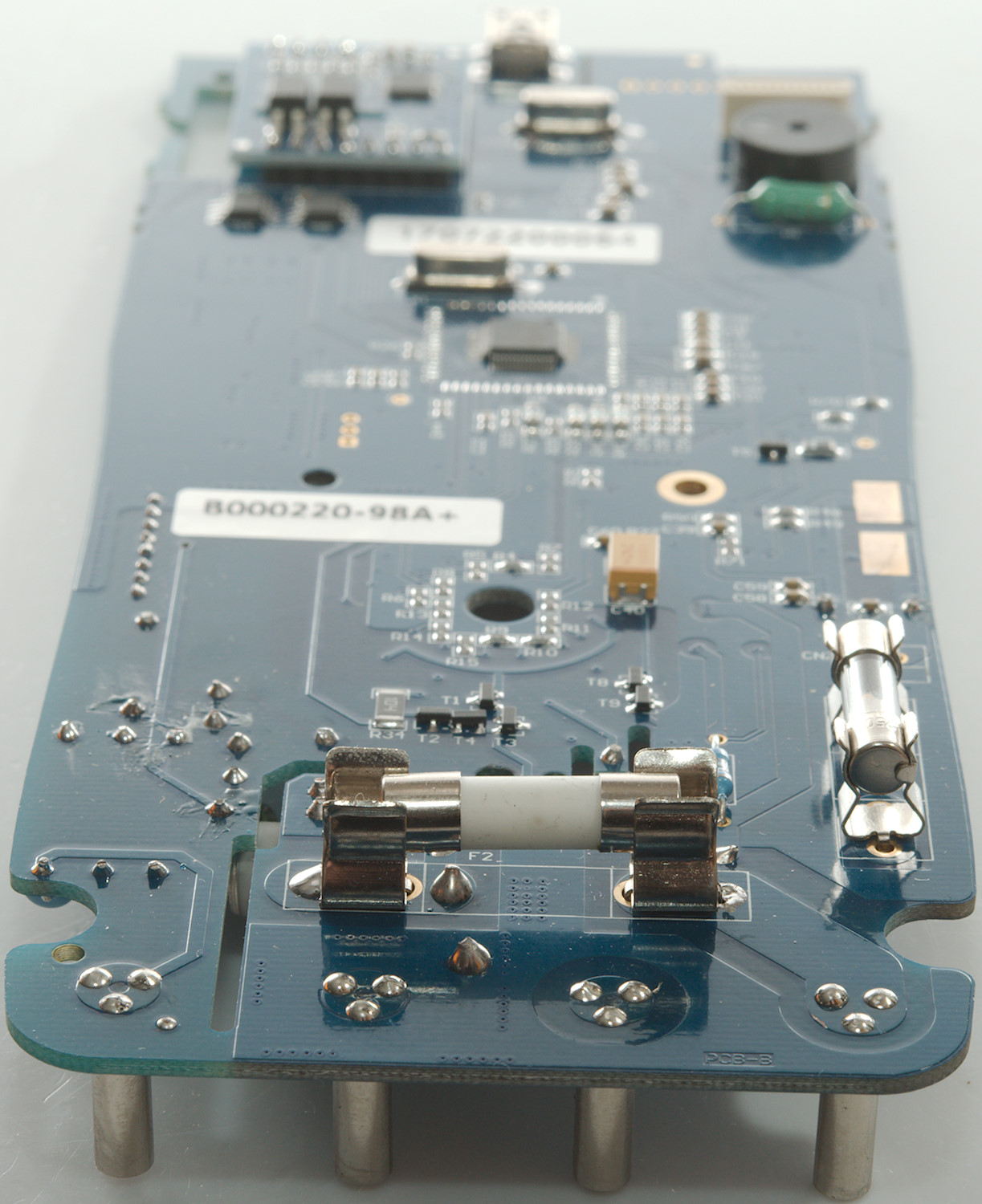
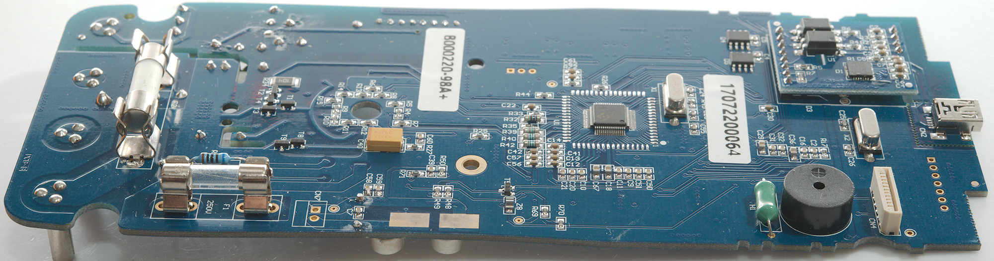

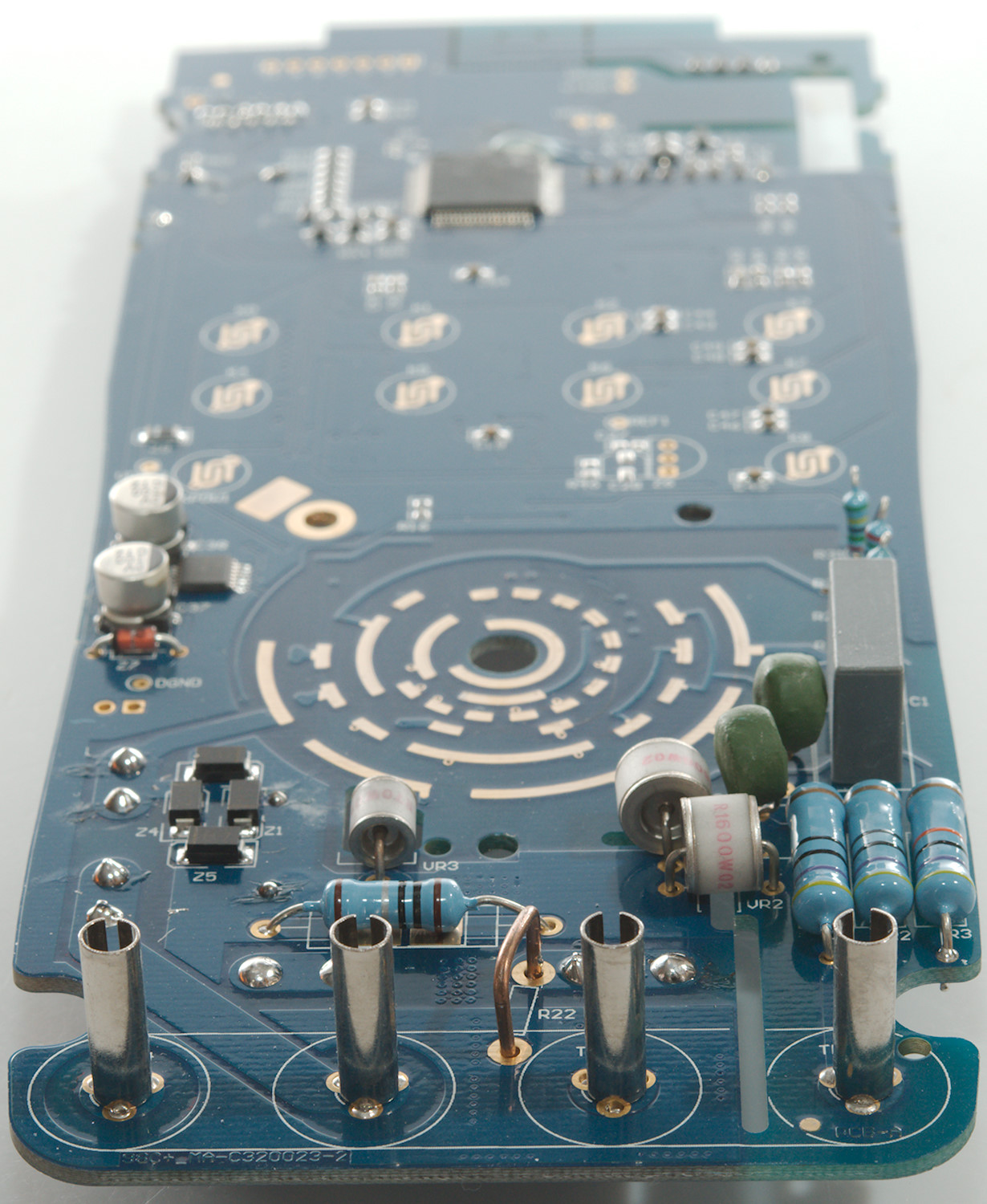
The voltage input terminal has 3 paths, one with fairly high input resistor (470kOhm) and two with lower ohms value (2x470ohm), both followed by a PTC (PTC1 & PTC2) and a GDT (VR1 & VR2) to common. There is a unmarked capacitor for AC input and the voltage divider resistor (R28..R31: 4x2.5Mohm).
The mA current shunt (R23: 1ohm) is here, together with the current shunt protection diodes (Z1, ZZ3, Z4, Z5).
The power supply (U3: Marked IF33) and maybe one chip more (D5: Marked CM011B / 5AKG4 / CNQH), this chip could also be some other functions.
The main processor is here (D1: Marked 68ALKZTG4 / 430F5327 / EV K).


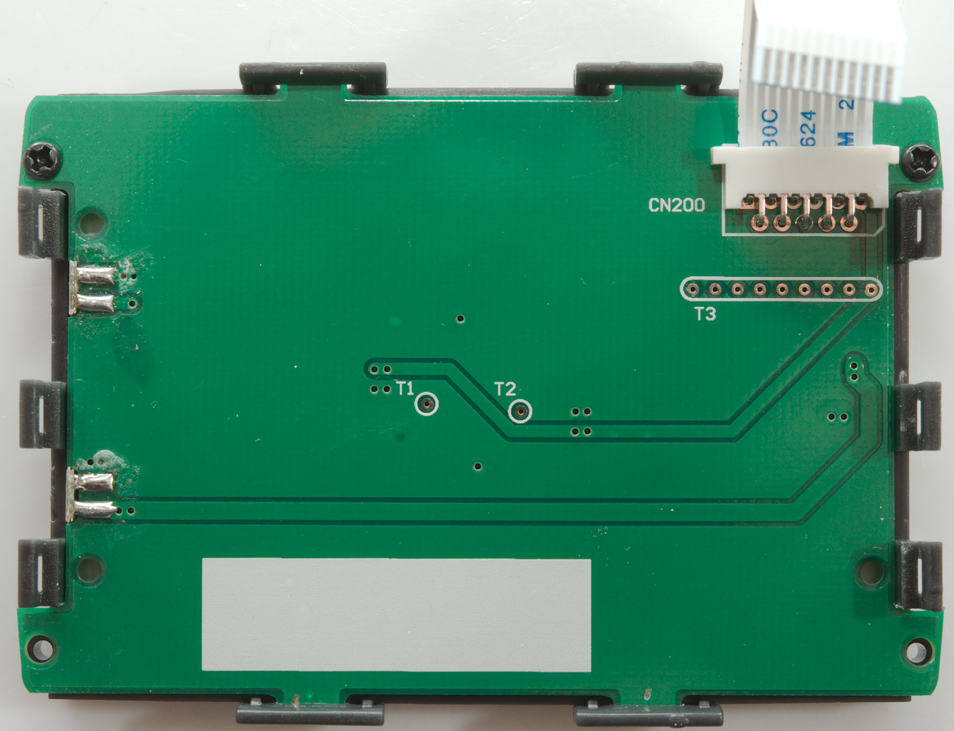
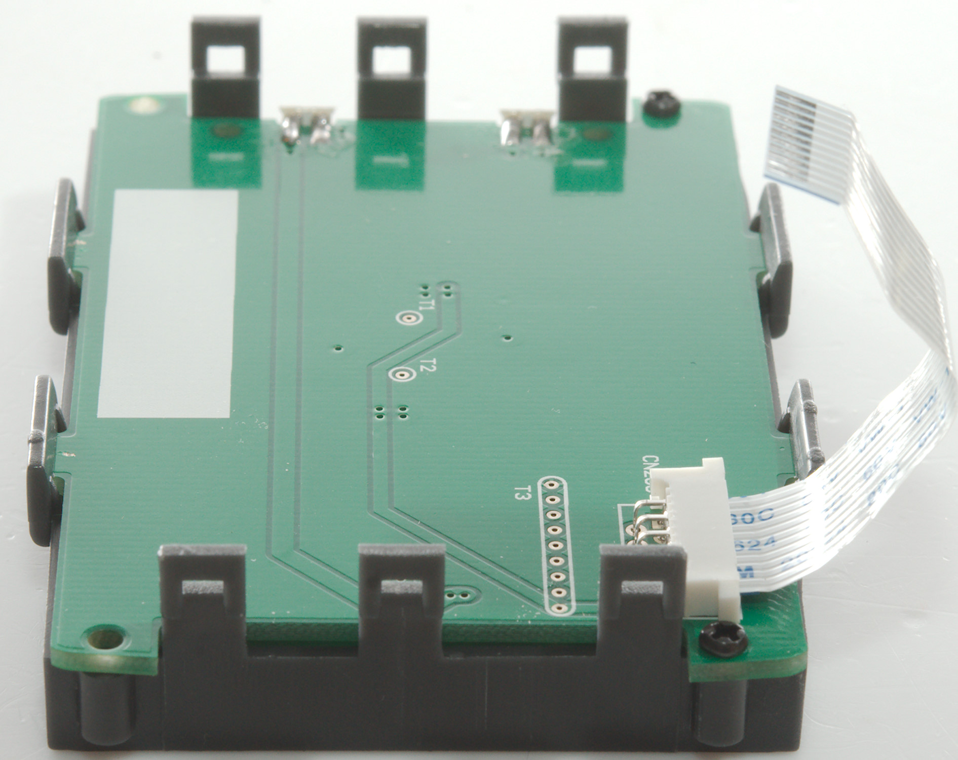
The display module required two screws and four clips to open.
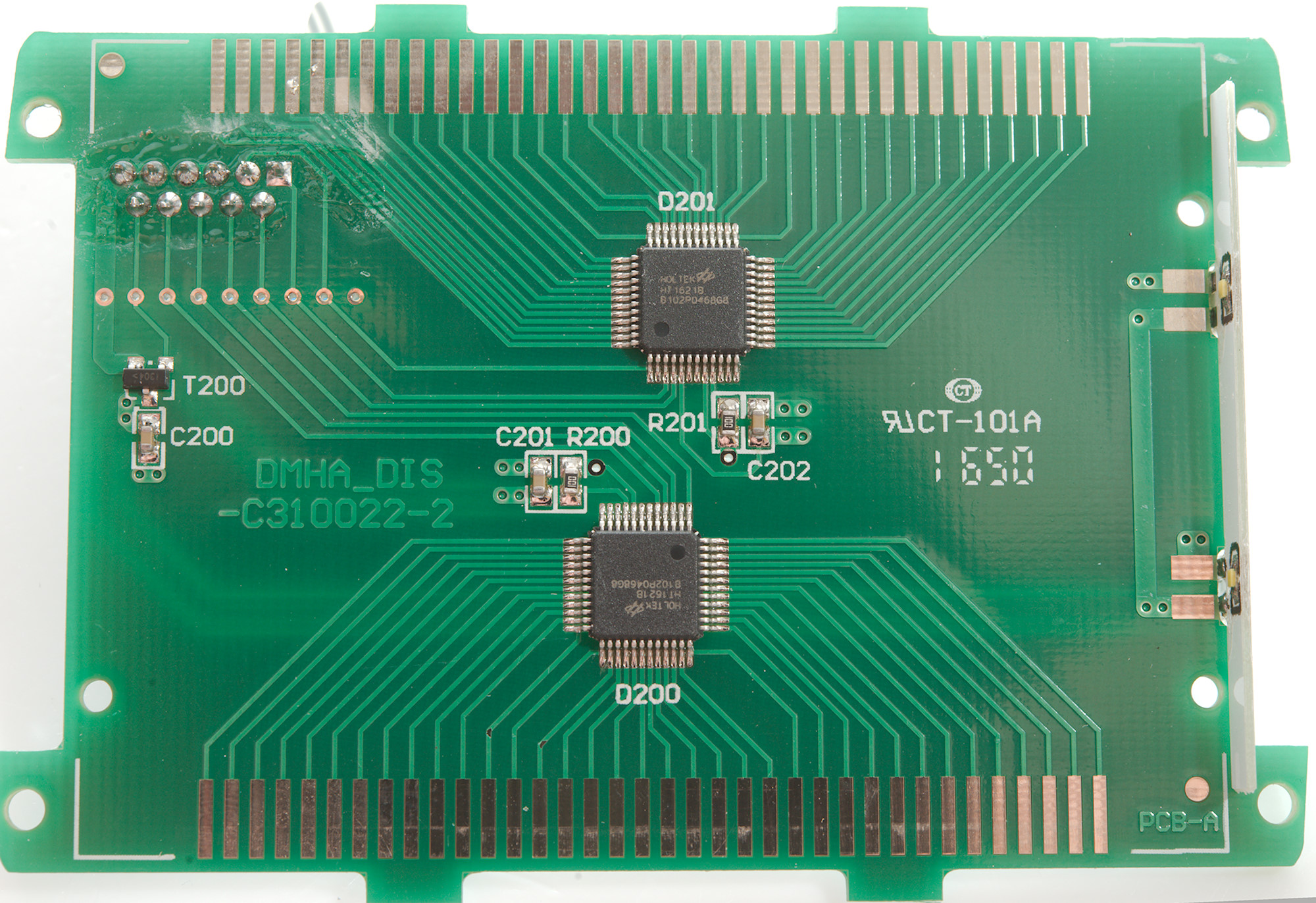
It has two LCD drivers (D200 & D201: 2xHT1621B) and a transistor (T200) to control the backlight.

The backlight can be seen at the back of the circuit board.
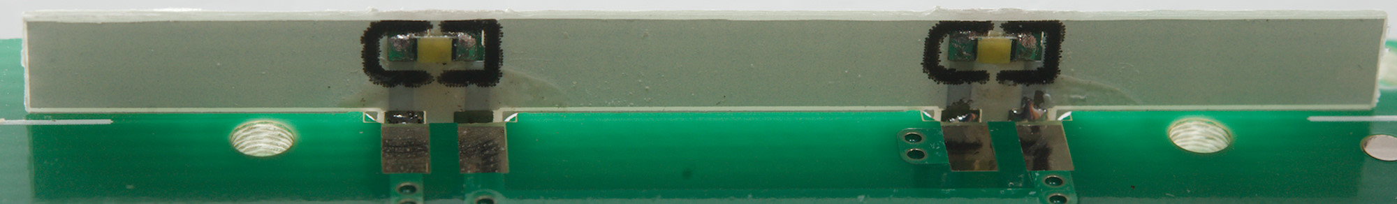
A closer view of the two leds.
Conclusion
The meter has what looks like a decent input protection, but I am not sure the distances are enough and the USB output has rather low creepage distance. The fuses are only for low voltage/current, not for CAT III. I.e. the CAT rating is not correct.
The meter can measure a lot, has good usage of the secondary display, but there are too many issues:
-
Range switch did initially not work fully, it had to be rotated a couple of times before it worked in all ranges.
-
min/max is not working correctly.
-
Internal temperature sensor is 10°C wrong, i.e. all thermocoupler measurements are 10°C wrong.
-
It is a bit cheap not to include a thermocoupler with the meter.
-
PC software do not work.
-
Capacity range has a –0.1nF offset and REL do not work, because the meter is in overload.
Notes
I did complain on Aliexpress about the capacity fault, but it was ruled to be correct behaviour for the meter (Dealer: Instruments).
How do I review a DMM
More DMM reviews