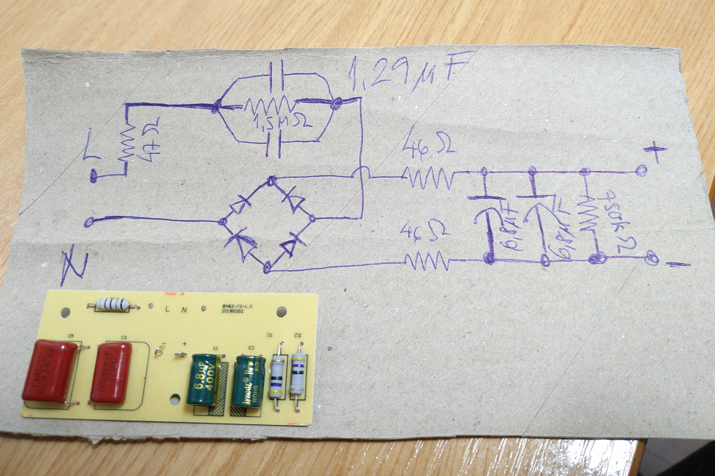
The circuit diagram shows a 1.5MΩ resistor between two polyester metal film capacitors, in reality that is two 750KΩ surface mount resistors in series like the one at the output. The above 1.29µF figure is the capacitance sum of both caps (0.82µF + 0.47µF). The aforementioned SMD resistors and an MB10S bridge rectifier are by the other side of the circuit board.
The driver yokes/plugs into a rectangular board with 9S2P 3528 led emitters. My brother told me the lamp was too bright, you know what this means don't you? O:)
As I see it, the capacitance value of the capacitors before the bridge is what I should play with. Since there are two, disconnecting the 0.82µF one should do, reducing the first precharge stage to 0.47µF instead of 1.29µF. Installing a mains rated switch in series with the big cap would also be nice, allowing two different levels of driving current.
Wellp, if you have something worthwhile being said you can do so, I am no engineer yet. :-D
The capacitors are for preventing flicker, not much to do with controlling brightness. It’s the 47Ω resistors that are responsible for limiting current to the LEDs.
The 1.5MΩ is a bleed resistor to drain the capacitors so the light shuts off quickly rather than fading out over a longer time.
Fairly standard cheap driver. The resistors in parallel with the capacitor is to discharge them when you unplug it, this means you will not get a chock if you touch the plug. Resistors are used in series to better withstand the mains voltage. The 47ohm resistor are used to limit the peak current.
The two 6.8uF capacitors are not strictly necessary, but they will reduce flicker.
And as you correctly guessed the uF capacitors controls the brightness, they are used as lossless series resistors.
Pretty sure we’re the wierd ones, only in America do they not teach you calculus when your two, instead electing to wait till you’re 20 and paying them $4k a class to get to learn it…
Thanks for the contributions zak.wilson and HKJ. I could also sense the pre-bridge stage 47Ω resistor was there to limit current flow to the poliester caps, being the value of these the main current output tuning thing as they pose a limit to the maximum amount of charge which can flow each cycle (100Hz effective here because 50Hz AC).
LoL! No need to dramatize nottawhackjob and Cereal_killer, in Spain you can learn what you can :)) learn, as anywhere else. I left my university studies super early due to health reasons, but of course I do not see it pityfully as everything has its justified reasons in our self-discovery trip. $4K is worth many courses here if I am not mistaken, what does that buys you there?
Thanks, I can now sort of see more clearly how much it can impact driving current and looks like it is around proportional to capacitance (allaboutcircuits.com calculator here).
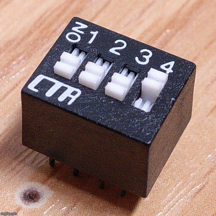
On a related issue, I was thinking in using a DIP switch to connect different capacitors at will and thus vary capacity and driving current at will. I have some old switches lying around:
Typical rating for this kind of switch is 24Vdc, with insulation resistance listed as 500Vdc (just checked O:) this). This to me means it could be used, but switching while powered should be avoided. Is this right or too daring?