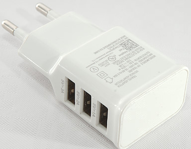
newCARPRIE 5V 2A 3 port usb charger EP-TA20JWE
Official specifications:
-
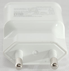
Plug Type: EU Plug
-
Output: DC 5V 2A(Max)
-
Input: AC100-240V, 50-60Hz, 0.5A
I got it from ebay dealer Funny Smart Devices Store
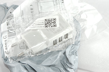
This cheap charger arrived in plastic bag inside a envelope.

The text on the charger says something about 9V, that is not possible, this charger is 5V only.
Measurements
-
Power consumption when idle is 0.13 watt
-
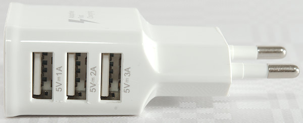
The top usb output (Marked 1A) is coded as Apple 2.1A
-
The other two Usb output is coded as usb charger (DCP)
-
All USB outputs are in parallel
-
Weight: 30.1g
-
Size: 75.7 x 36.4 x 23.7mm
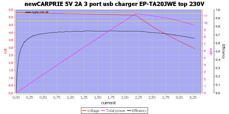
The top 1A rated usb output can deliver a bit above 2A and overload protection do not look very good.
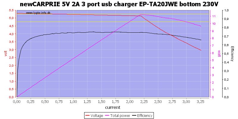
The bottom 3A rated usb output delivers exactly the same as the top connector.
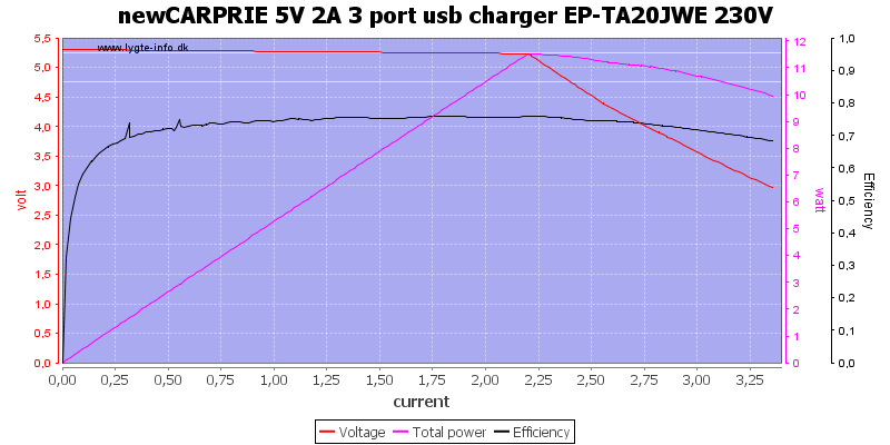
And using all usb outputs together is also the same, there is no more current available.
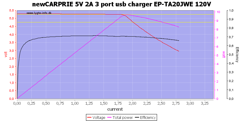
Current is lower at 120VAC
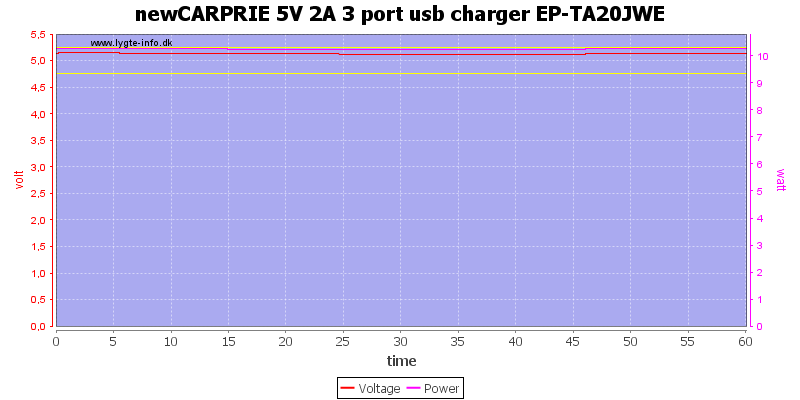
Running the charger with 2A total output current for 1 hour worked fine.
The temperature photos below are taken between 30 minutes and 60 minutes into the one hour test.
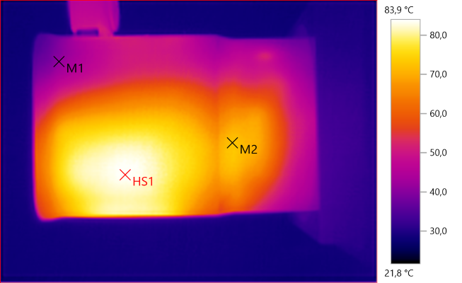
M1: 41.2°C, M2: 72.2°C, HS1: 83.9°C
HS1 is the transformer.
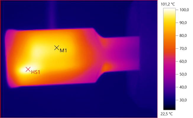
M1: 92.6°C, HS1: 101.2°C
Here HS1 is probably the rectifier diode.
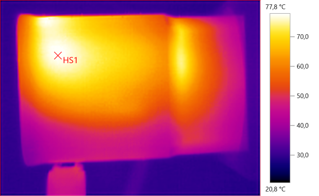
HS1: 77.8°C
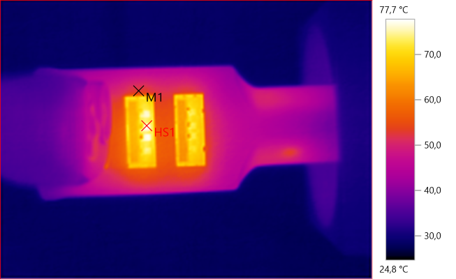
M1: 52.7°C, HS1: 77.7°C
The back of the usb connectors (HS1) are heated by the transformer.
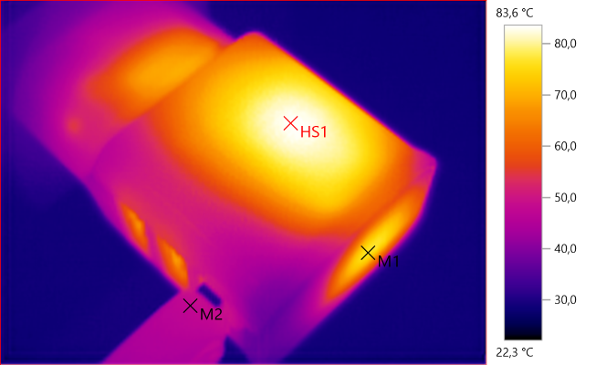
M1: 76.5°C, M2: 47.6°C, HS1: 83.6°C
THe top of the charger (M1) is heated by the rectifier diode.
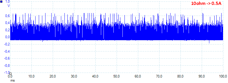
At 0.5A the noise is 150mV rms and 885mVpp, this is very high
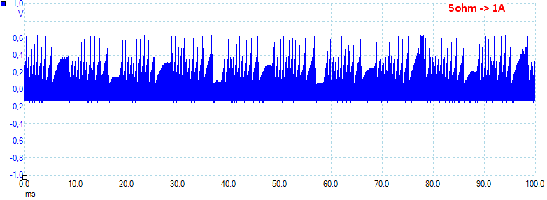
At 1A the noise is 191mV rms and 885mVpp.
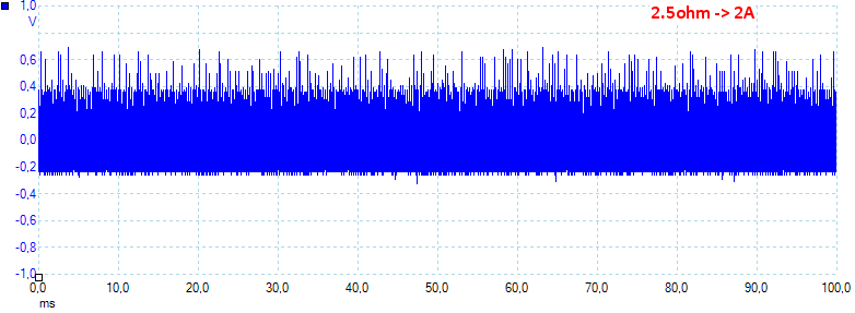
At 2A the noise is 247mV rms and 1027mVpp, here the noise is even higher.
Tear down

Some pressure with my vice and the lid popped off.
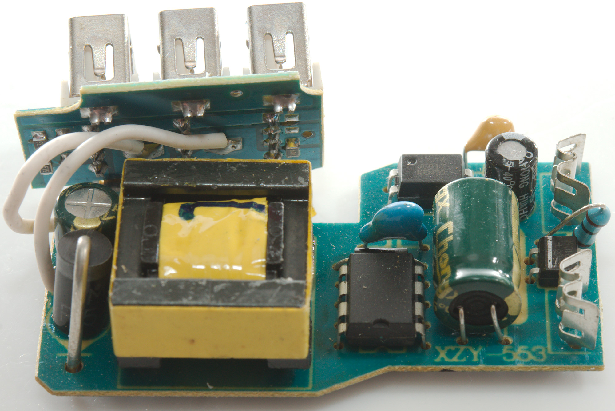
The circuit is in two parts.
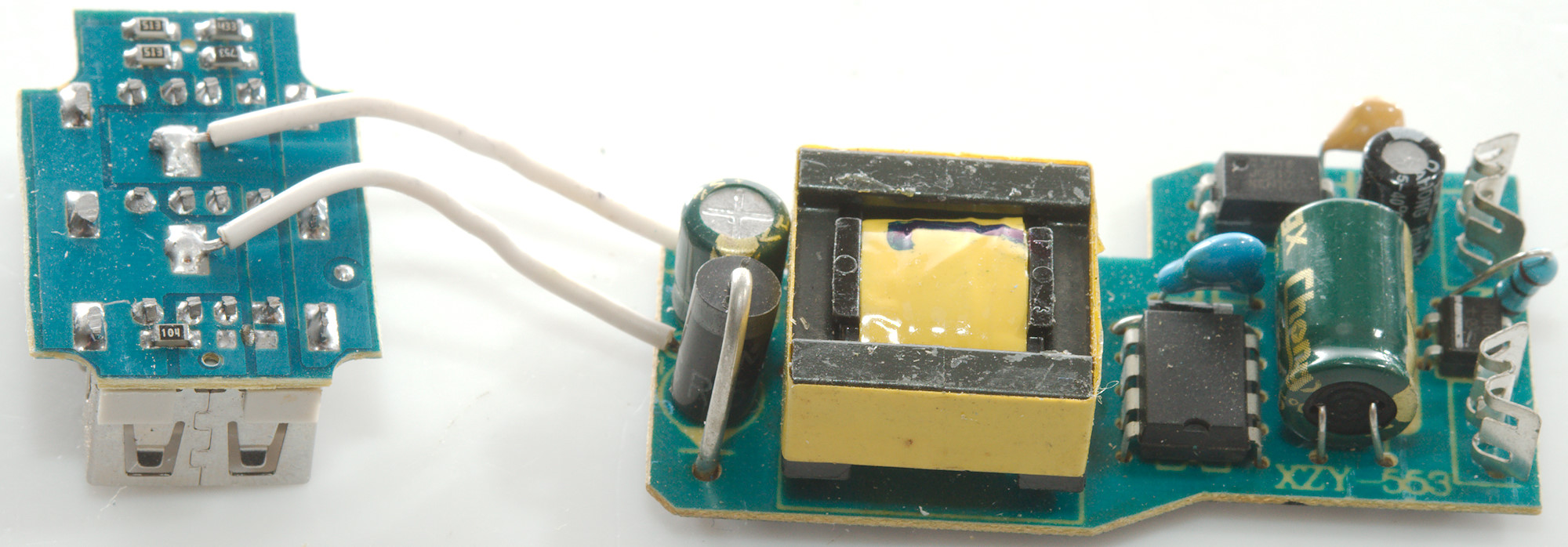
The large circuit is the mains switcher, the small circuit is the usb connectors and coding.
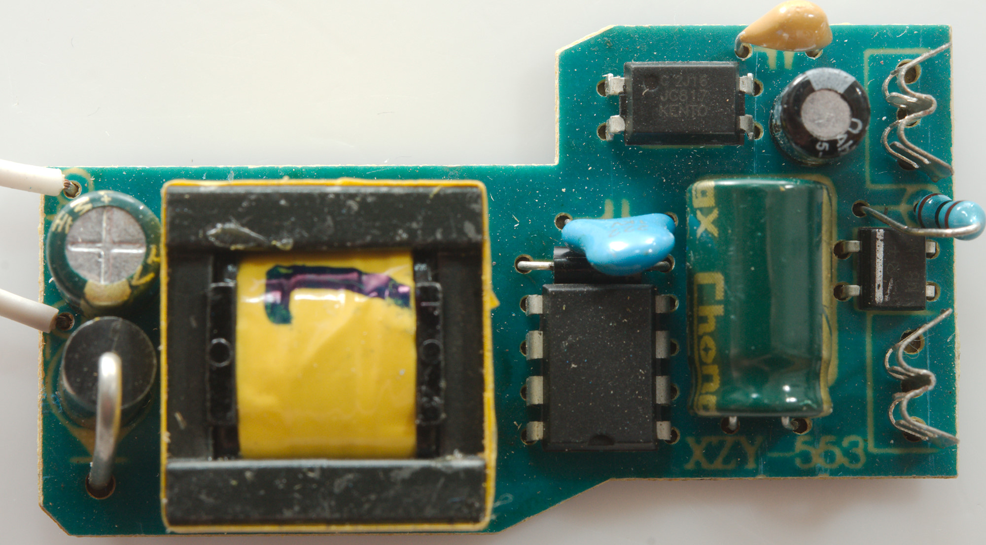
This is a very simple design with a resistor instead of a fuse, then a bridge rectifier and a unmarked switcher IC. Between mains and low volt side is the opto coupler and the fake safety capacitor (Blue 1kV, next to IC)
On the low volt side is a large rectifier diode and the smoothing capacitor.
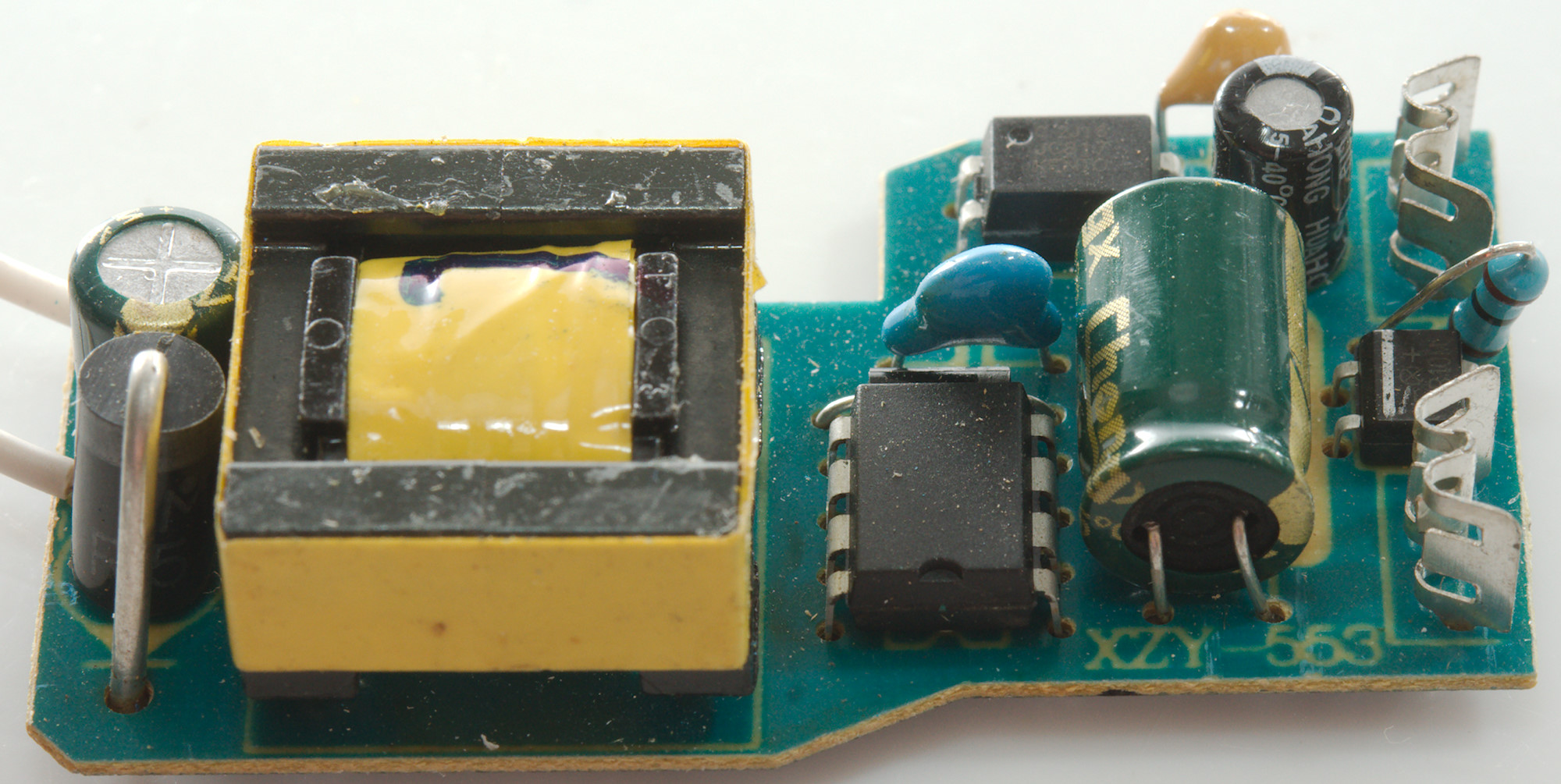

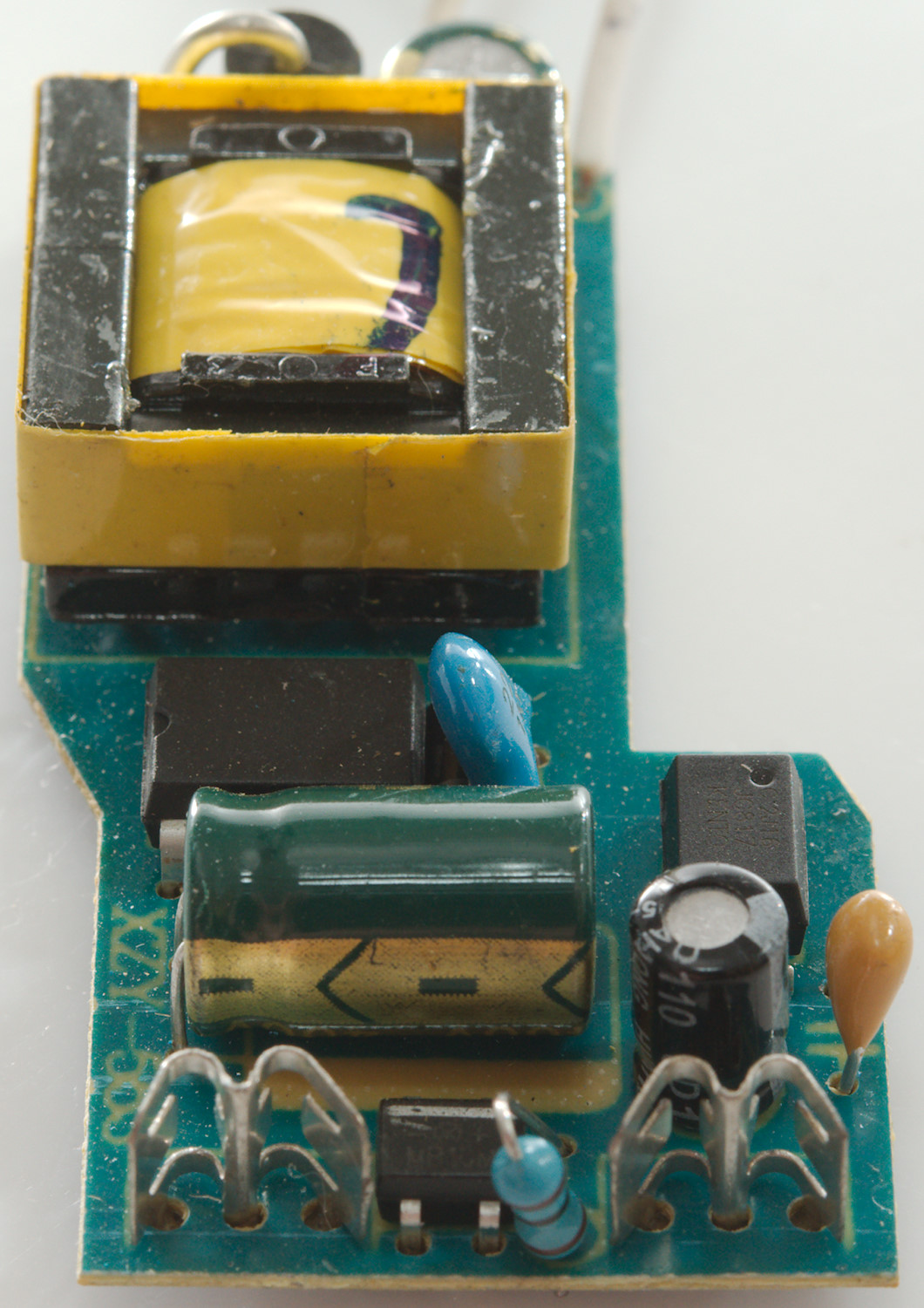
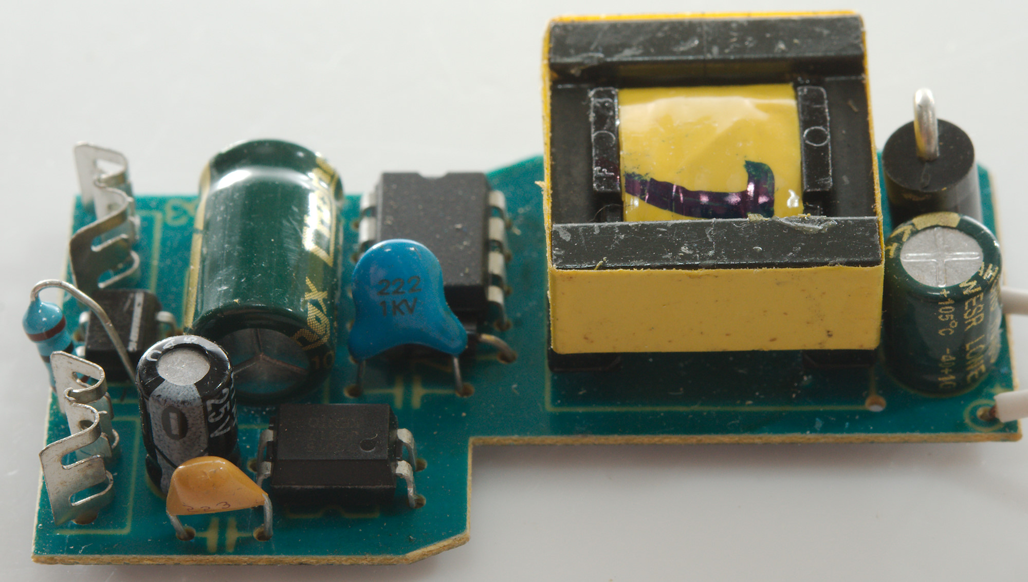

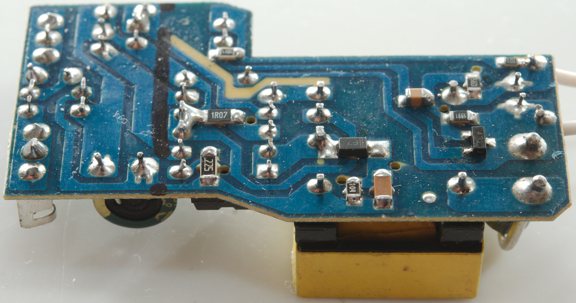
Resistors and small capacitors are on this side and a 431 reference IC.
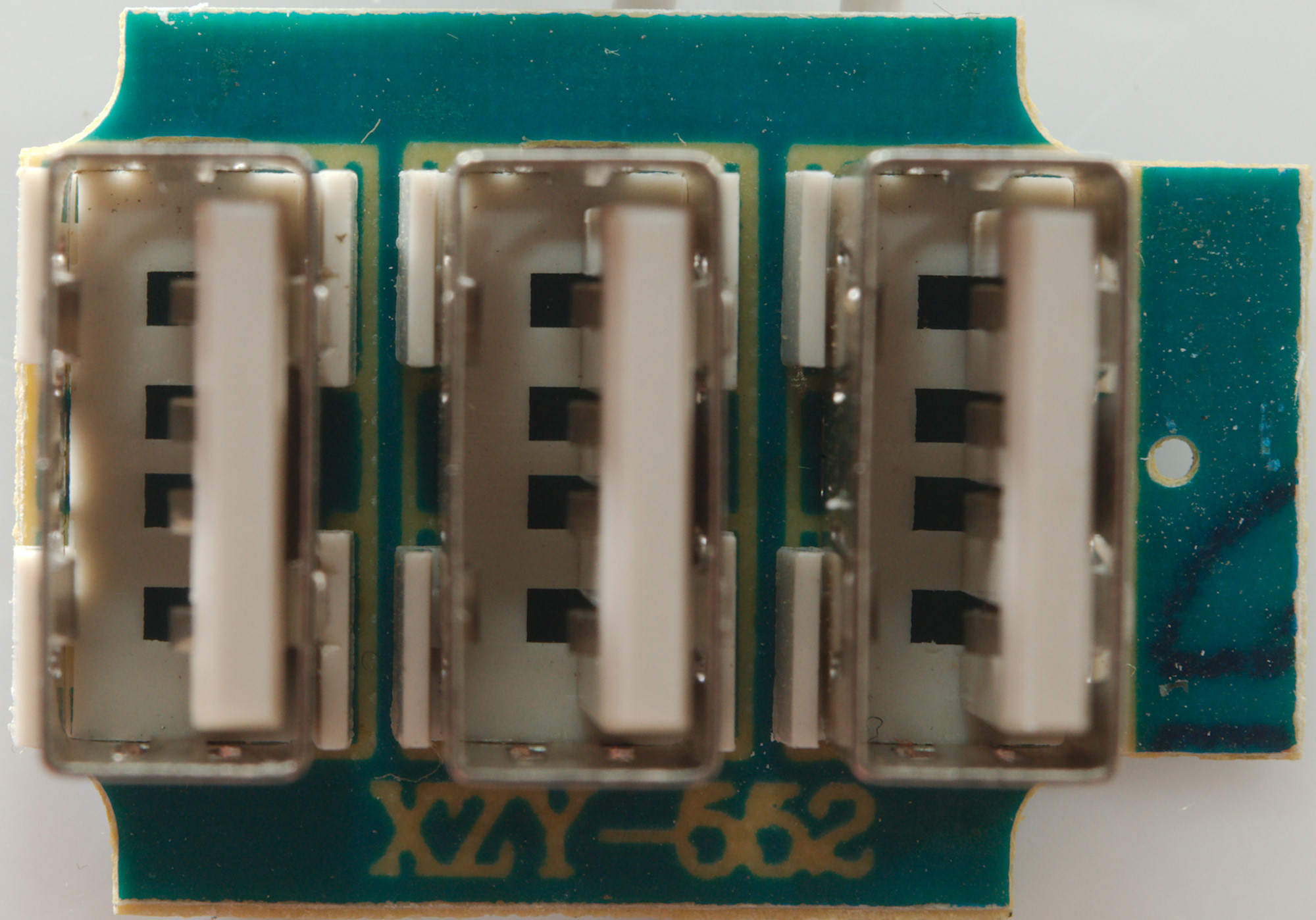
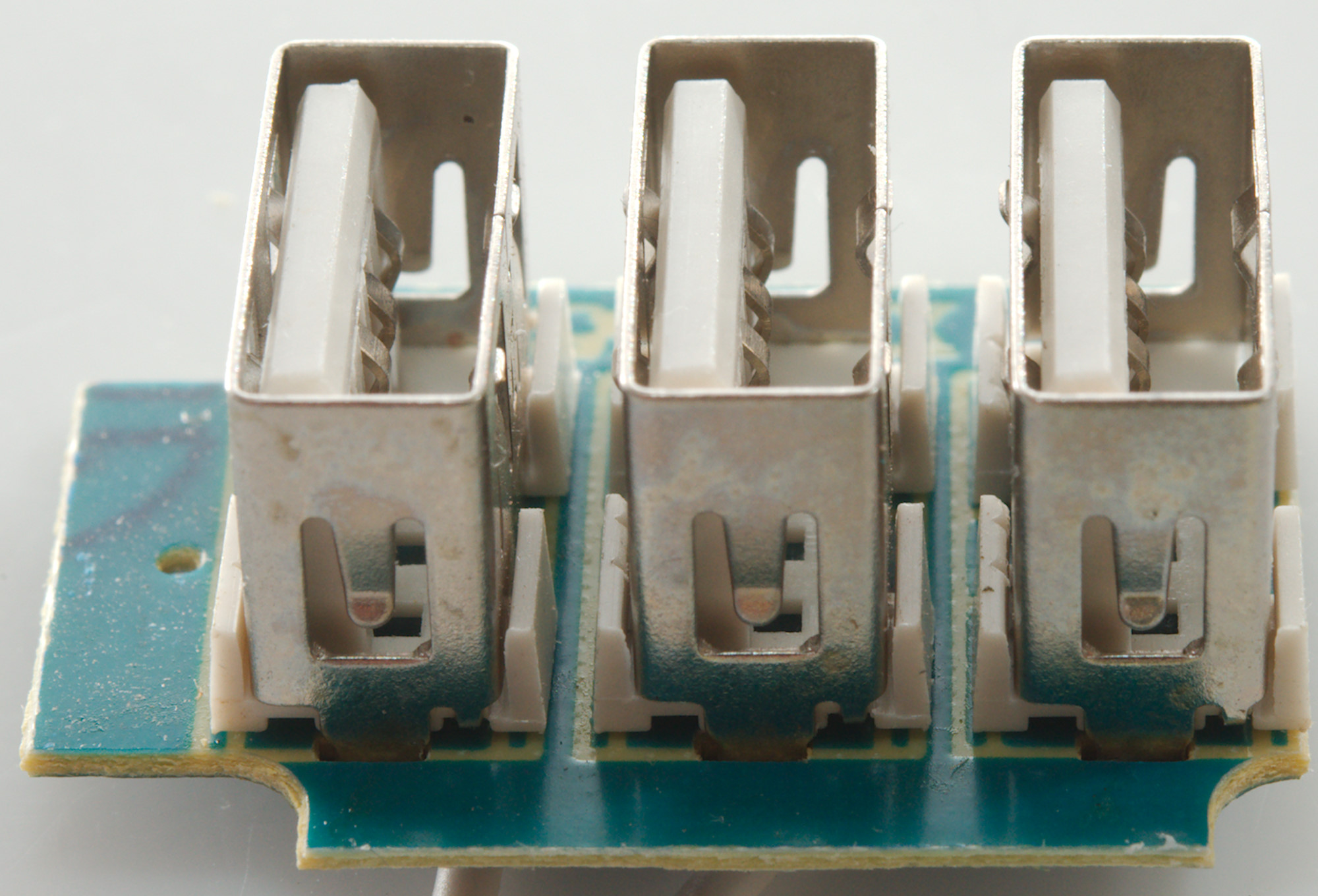
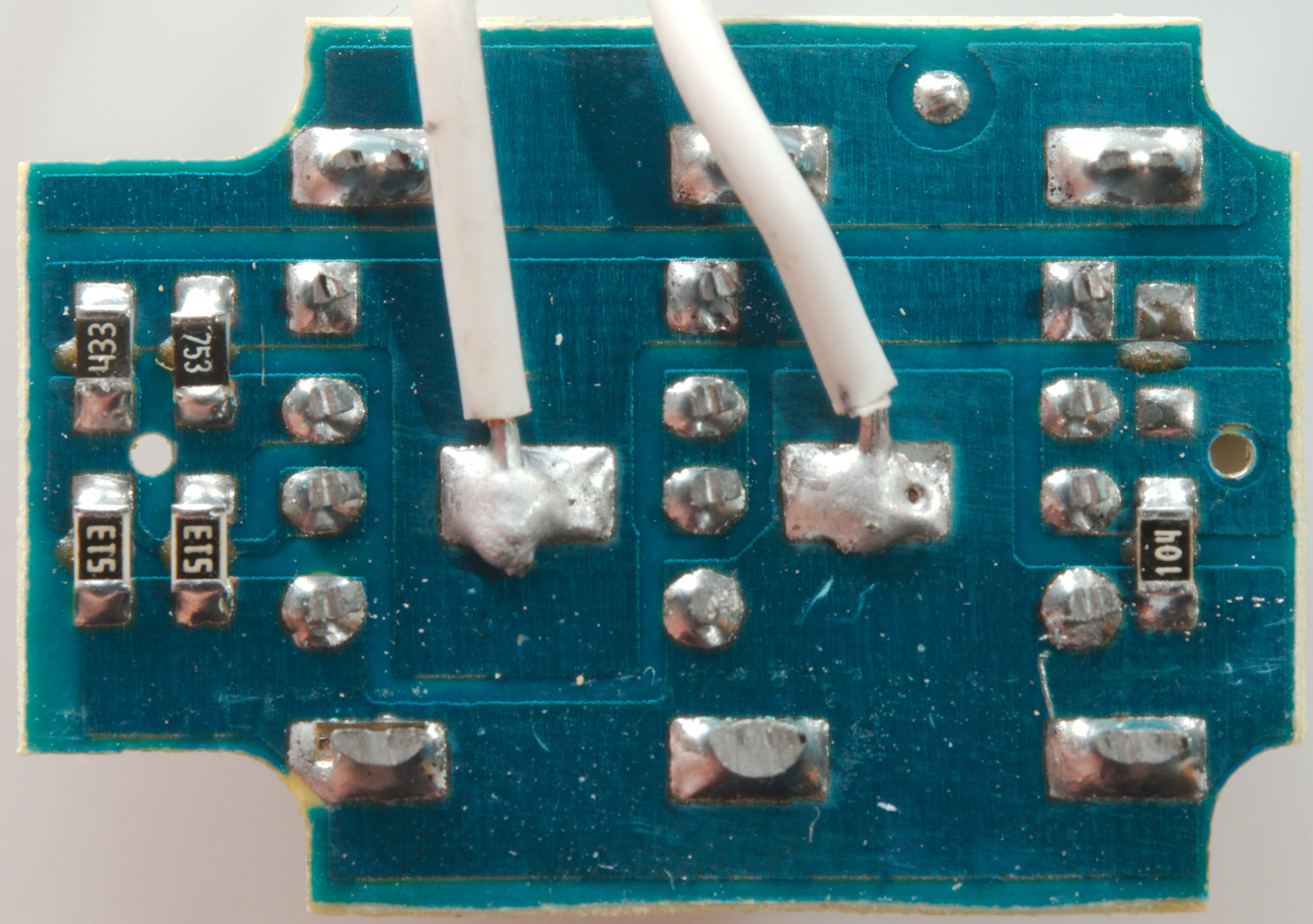
The coding resistors are on this circuit board.
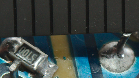
There is supposed to be above 6mm between low volt side and mains, here is about 1mm!
The charger failed the 2830 volt and the 4242 volt test between mains and low volt side, this makes it unsafe anywhere in the world.
Conclusion
This charger has way to much noise, bad performance and is in the death trap category, stay away.
Notes
Index of all tested USB power supplies/chargers
Read more about how I test USB power supplies/charger
How does a usb charger work?