I am not very fond of the way FW3A implemented tail e-switch for the simple reason that it meant a significant diameter increase.
So I was exploring other methods, namely:
passing one or more wires along the tube
using bleeder resistors on the MCPCB and driver in the tail (like Folomov 18650S)
using bleeder resistors on a separate PCB and driver in the tail (like Ultrafire UF10)
To be honest I’m not very happy with any of them, for various resons.
Now I found a new way that I haven’t seen implemented. Imperfect as well, but the tradeoffs are somewhat different.
Start with a plastic battery tube (carbon fibre would be perfect), slightly too long.
Plate it with metal (copper + nickel?).
Trim the edges to remove the plating from the ends.
Now…it becomes FW3A-like tube-in-a-tube. But:
would the cost be reallistic for anything but the most expensive lights?
how is durability of plastic threads covered with metal?
threads machined in carbon fibre? Does it even work reasonably?
ADDED: I learned that gluing in a metal thread is the best way to do it. Extra cost but doable
threads are conductive which makes it harder to do mechanical lockout
what would be contact resistance on the internal tube? Especially after oxidation.
I’m not sure if the carbon fiber will work or not, but seems like a good idea.
There is a way to do it with an all metal tube, that would be much more reliable and end-user friendly (plus smaller in diameter) than the fw3a.
I have been wanting to build one for a while but unfortunately I dont have a lathe or mill at my disposal anymore so I was thinking of throwing a cad drawing up here to see if somebody wanted to run with it.
I think there will always be a thickness increase over the minimum (or a bleeder), because there will always be need for a second current path. We need to have a complete circuit with the driver while being able to have an open circuit with the LED at the same time. This is one of the reasons why a driver in the head is very convenient.
To me, the FW3A could have been much thinner in FW1A form. Simply keep the head the same diameter as the outer tube. But then the FW1A was longer due to reflector length. Find a short optic? Mount LED directly on driver (Zebralight’s trick, among others)? I think the FW3A did pretty well, my biggest complaint was the design of the actual button. Tail-clicky lights have been impossible for me to accidentally activate forever, but Lumintop decided to do things very differently for the FW3A. They reinvented the wheel and it just doesn’t roll like it used to.
What about a flat-flex wire ran in the tube which folds over both ends of the tube and makes contact with the driver and tail. Then make a new SW board so the current flows through the tail cap threads while the bottom of the switch board (which traditionally makes GND contact to the body) interfaces with the flat-flex cable for the switch signal?
I’ve thought about this a lot, I tried to make an anduril driver for a manufacturer that was powered by bleed resistor but the problem with that is you have to slow the pwm frequency down to the hundreds of hz range in order to provide enough power to the driver (+ flows threw body only between pulses) so while that did work, and I do have a 18650s that runs anduril, it’s not commercially viable because of the horrid PWM.
I see that such wires are easily available, for example 24AWG sized 0.13*2.03mm.
Would you just glue it to the tube and remove the insulation at the ends? I can see it working in a mod but production might have problems with shorts…
Also, I wonder about abrasion, especially at the contacts. As you twist the tailcap there would be tail board rubbing against the wire.
For mass manufacturing, extra conductive layer can be used between two isolation layers. This is common solution for high-frequency devices which need separate ground, as far as I know such isolator-conduction-isolator sandwich layer can be made with electro-plating technology.
MCU choice, I don’t recall the MCU they used to do it but the t85 is just to power hungry (not really though, it’s quite efficient but in this case it requires more current then the stock driver did). My first version utilized a t13 (obviously with much more basic Fw) and it ran just fine at high pwm rates, it wasn’t till my second version with the t85 I learned of the issue. I had to slow the pwm rate down in code as well as enable the 8x clock divider fuse just to get it to not shut down above medium modes.
Even still, if you go from off to turbo it has problems (but you can start at low/med and ramp up).
The link you posted isn’t exactly what I was thinking… I have some flat flex cables from inside a monitor I converted to LED, they’re high strand count so I was thinking even if they do abrade away with use there’s so many of them you should get a pretty good usable life.
I’ve been thinking about it a bit - CF is indeed conductive and actually enough to be a potential source of problems.
But this is easy to overcome - use some other kind of fibres to reinforce the plastic. Glass / aramid / cellulose / …
There’s a similar thing that could be used - make the driver-tailcap as a single rigid-flex board. That would enable arbitrary number of conductors (non-conductive battery tube, rgb tail indicator etc.). But wouldn’t be really replaceable, woudn’t allow different batt tube lengths and abrasion would still be a problem.
Has anyone ever made a light where the tail switch simply pressed onto the battery and moved it? The battery could then press a switch on the driver board. You might need a plastic carrier to protect the battery wrap.
Here I copied over the idea I presented in tterev3’s post… I feel like this is viable solution that could start conversation.
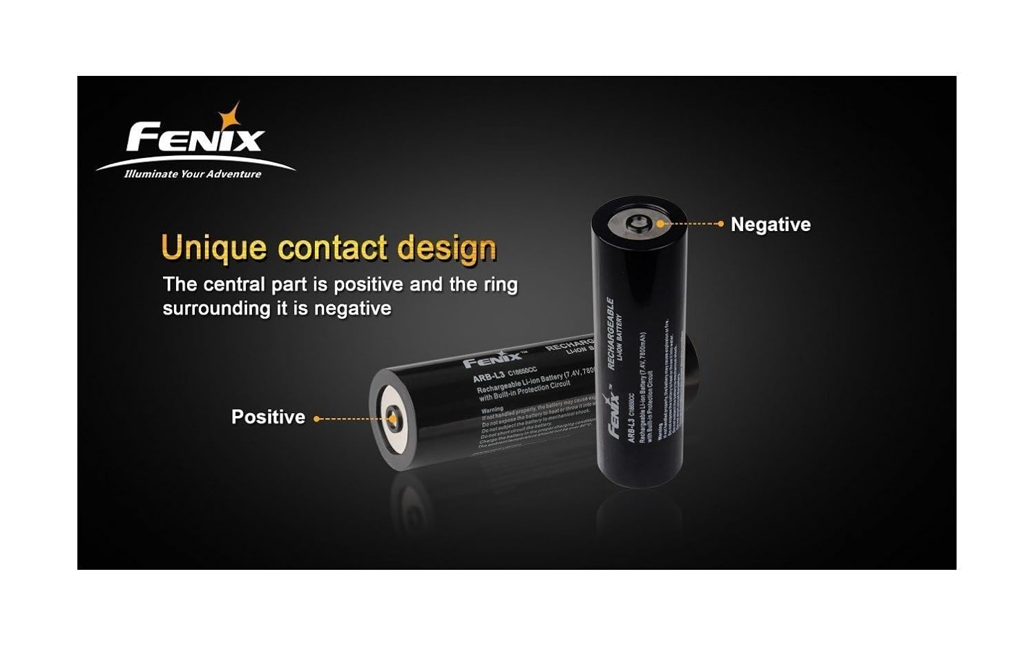
I have had ideas though. They would work I believe, but trade off those few mm of diameter for a special cell design (like the Fenix did with the LC40) with + and - contacts in the front, along with a “-” at the rear in the normal position. The driver would be designed to take main drive current through the front two concentric contacts, bypassing the tube altogether. The tube can be isolated from the main power delivery circuit, and re purposed as a switching signal.