Hello BLF,
Hope that everyone is doing well in 2020 and keeping healthy and safe. A few months ago, I was toying with the idea of building a more sensible, everyday flashlight driver, as opposed to my (admittedly impractical) GXB-series high-power drivers. The result is the Lume1 driver.
##############################################
Update Aug 2020: Lume1-fw3x is now available for sale thanks to Neal from Nealsgadgets.
Buy a Lume1-FW3X!
Get the Lume1-FW3X driver from Nealsgadgets: https://www.nealsgadgets.com/products/lume1-fw3x-driver
>> For a limited time, use Coupon Code LUME1 for 20% off <<
Many thanks to all forum members for their input & suggestions, and TK for her support with the firmware.
Warnings: Note that this DIY project is not recommended for the beginner and involves soldering small pads and components! The lume1 driver was made as a personal hobby-project and has some quirks and features you should be aware of before purchasing or building one. Please read the manual and this thread in detail before committing to including one for your project. Finally, this driver (Rev B) does not have Reverse Polarity Protection, as a bid to improve performance for Turbo mode. Please ensure that you do not insert the battery backwards.
Calibration: The Lume1 driver uses a dedicated temperature sensor with +-1C accuracy, and a regulated VCC. There is no need to perform Temperature or Voltage calibration in Anduril.
Future: Thanks so many people on BLF for making the Lume1 driver what it is today. Please help make it BETTER! Feel free to send me feedback, criticisms, and suggestions either to this thread or via PM. I will consider all of them for future versions.
Downloads & Firmware Updates
Github for Lume1-FW3x Manual, Anduril Firmware, Updates, etc:
- https://github.com/loneoceans/lume1-fw3x
- Recommended Fuse settings: Low, high as 0xE2, 0xDE respectively.
- For flashing - note that the 01/20 Rev B driver (printed on the PCB) has MISO and MOSI pins swapped from the Noctigon PogoProgrammer pinout. The 06/20 Rev B driver fixes it to be consistent.
- Anduril1: https://github.com/loneoceans/lume1-fw3x/tree/main/anduril1
- Anduril2: https://github.com/loneoceans/lume1-fw3x/tree/main/anduril2
Aux LED Boards
LEDs can be purchased on Aliexpress (see description in OSHpark link). Recommended to use thinner 0.8mm PCB option.
Aux LED wires recommended to use 30AWG wire wrapping wire, or even better, teflon coated wire for best results. Single core is easiest to solder.
- Aux tri-LED Board: https://oshpark.com/shared_projects/DwJI67OX
- Aux RGB-LED Board (Updated Rev B, easier to solder pads): https://oshpark.com/shared_projects/mtHUb4gp
##############################################
Introduction
Introducing the lume1 - 3A Constant Current BuckBoost + FET driver

Some of you may have seen this thread about a switching driver I was thinking about. The goal was to develop an open-source, high efficiency, constant-current regulated driver, while using community open-sourced firmware. The motivation also came from the fact that there didn't seem to exist many high efficiency drivers around, with essentially all drivers being inefficient (but low cost) linear-regulated drivers using some combination of 7135s + FETs.
I received a lot of great input from forum members; many thanks to them. Over the week I was able to find some time to work on this project on and off. At this point, I think there are some developments worth sharing. Here's the first prototype of what I'm calling the lume series of drivers.
This is the lume1-fw3x driver, designed specifically for use with the 18650 FW-series of flashlights like the FW3A or FW3C, and therefore was designed with a 22mm-nominal (21.7mm) diameter. Components were specifically chosen to fit in the very low z-height of the FW3 flashlight cavity, especially the inductor. Certainly a bigger one can be used in other designs for even lower DCR and efficiency. The lume1 topology will be adapted to fit other drivers, but the FW3x-series was the first candidate.
Here's how it looks like:

Above - the lume1 CC-BB+FET driver. For those wondering about the PCB, I used OSHPark's new AfterDark option which is very pretty. 
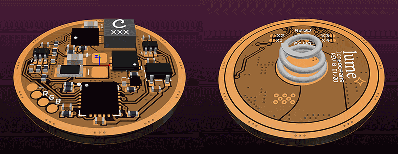
PCB design of the lume1 LED driver; designed with low cost assembly in mind (all on one side, PCB only has 2 layers), revision B.
The FW3x was chosen as an ideal candidate for this driver due to its very compact size, great popularity, and high quality construction. The tail E-switch design is nice too, since it allows for a very clean, basically solder-free assembly (other than for the LED). I thought it would be a good match for this driver, though obviously the lume1 topology is easily adapted to any eSwitch flashlight, and more designs will likely be in the pipeline once lume1 has its bugs worked out. It's also possible to port this over to clicky flashlights running different firmware.
Hopefully this may be a driver that hobbyists will consider when modding their flashlights.
lume1 Driver Feature List
Here are some of the general features for the FW3 lume1. In no particular order:
- Input - 1S, e.g. single 18650, specifically since this was designed for the FW3x flashlight (5.5Vmax to 2.7Vmin)
- Output - designed for 1S LEDs (e.g. 1S for FW1x, 1S3P for FW3x etc)
- Regulation:
- 3.0A Output Constant Current Buck-Boost with 1024-levels of resolution
- FET on-board for Direct-Drive Turbo with Reverse Current Protection
- 21.7mm Diameter
- 2 Layer PCB, Single-side Components for low cost fabrication and assembly
- Very low stack height to fit in small driver space for FW3x
- Attiny1634 Microcontroller
- ToyKeeper's Open-sourced Anduril Firmware
- HarleyQuinn's 4:2 Pogo-pin Programmer compatibility (intl-outdoor sells programming pogopin kits)
- Overall Board Efficiency >90% for low to high-mid modes (up to 93.5%)
- External temperature sensor IC for better accuracy and precision
- E-switch (for FW3x) with hardware debounce filtering
- Low quiescent current for long standby times
- RGB outputs for optional LED aux board
- 4 additional solder jumper pads (no FW use for them yet, but it's an option for the future)
Keep in mind that this is a first prototype and there should be improvements coming. I tried to keep the design as simple as possible and reduce component count, without adding too much unnecessary things, with the idea of making it cheap to fabricate and assemble.
Driver Development
As with all the drivers I've made, I built a simple development platform to evaluate the design I created.

This allowed me to evaluate the CC-Buck-Boost + FET topology, and also do some basic firmware testing on the 1634 MCU in an easy way. This platform also allows me to characterize the system easily.
Notice that the choice of MCU is the exact same one as used in some Anduril flashlights, such as the Emisar D4 V2 and Noctigon K1. The idea is to keep the design and pinout as similar as possible to enable easy portability of Anduril and similar community firmware.
Some modifications had to be made in terms of:
- HW definitions (pinout is very similar to Emisar D4V2)
- Temperature sensing - uses the more accurate external temperature sensor, but still possible to use internal sensor if desired
- Control line (use 7135 control signal to buck boost control line)
- Battery Sense (uses simple voltage divider here instead of VCC)
No changes were made to the core Anduril FSM codebase, so anyone can easily compile their own code and flash the 1634 themselves. Since I use Windows, the firmware was ported over to Atmel Studio. I will be writing a simple document on this process and releasing the code package on github and TK's FW codebase.
To keep things simple for the dev. board, I soldered a LH351 LED directly on the board for easy use. Fortunately, all hardware was tested to work as intended and the driver regulates well at 3A output across a variety of input voltages.
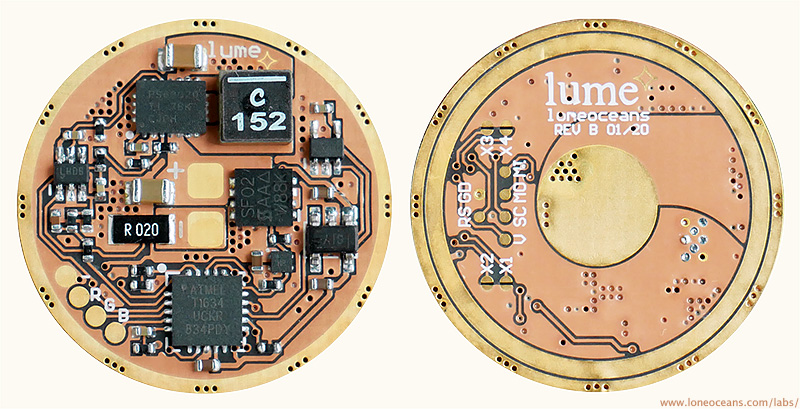
With the topology verified, a form-factor PCB was created and assembled. Notice how all the components are only on one side. The spring wasn't installed yet in this photograph.
For those with a keen eye, there is one downside to the FET drive, in that current still goes through the low-side current sense resistor, so max turbo is diminished slightly compared to regular FET drivers. I think this is still OK, since typical Turbo drive durations are around tens of seconds before throttling is required to prevent the flashlight from melting! It is possible to improve this further, but I felt that it started to take away from the elegance of the design.
Total power path resistance was measured as 4.6mR + R_sense.
Initial Prototype Builds
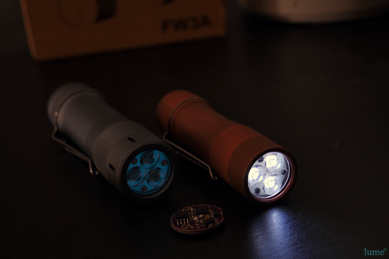
With the first prototype driver completed, the driver was assembled into a FW3C bead-blasted copper host I previously purchased from Nealsgadgets specifically for this project.
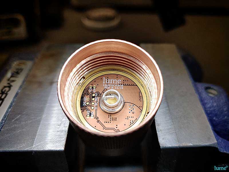
For those concerned, I did put some tape around the flashlight so as not to have it scratched by the clamp. I think this PCB colourway works quite well with the FW3C. The lume1 driver fits! No issues with the inductor hitting the driver cavity, as designed. Programming was done using a HQ pogopin and AVRISP2.
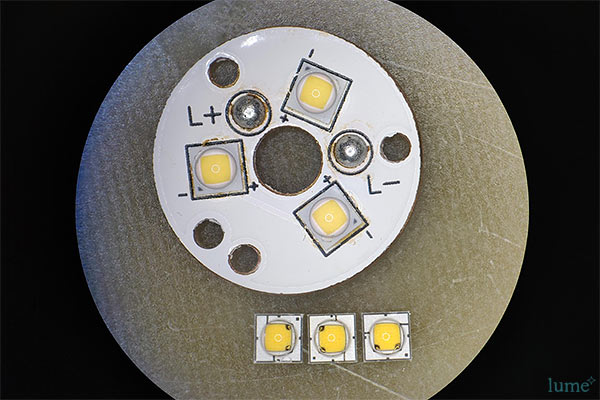
The original emitters were SST-20 4000K 90CRI. They seem to be quite popular, but I never really liked the tint, being very green especially at the lower power levels, and never really getting better unless driven at Turbo.
I thought this would be a good opportunity to use some of the fairly rare but extremely nice Nichia 219B 9080 4500K 'rose tint' LEDs. These were reflowed onto the original MCPCB. The thermal paste was cleaned up and replaced with Arctic Silver 5. Finally, a TurboGlow glow gasket was added between the optic and the LEDs, just for fun.
But does it work?
I'm happy to say that it does!
RGB AUX tri-LED & RGB-LED Board
To take advantage of the extra AUX LED features of Anduril on the 1634, a lume LED aux board was also developed. Two versions were developed, one using three banks of six 0402 or 0603 LEDs (which I call the triLED board), and another using RGB LEDs.
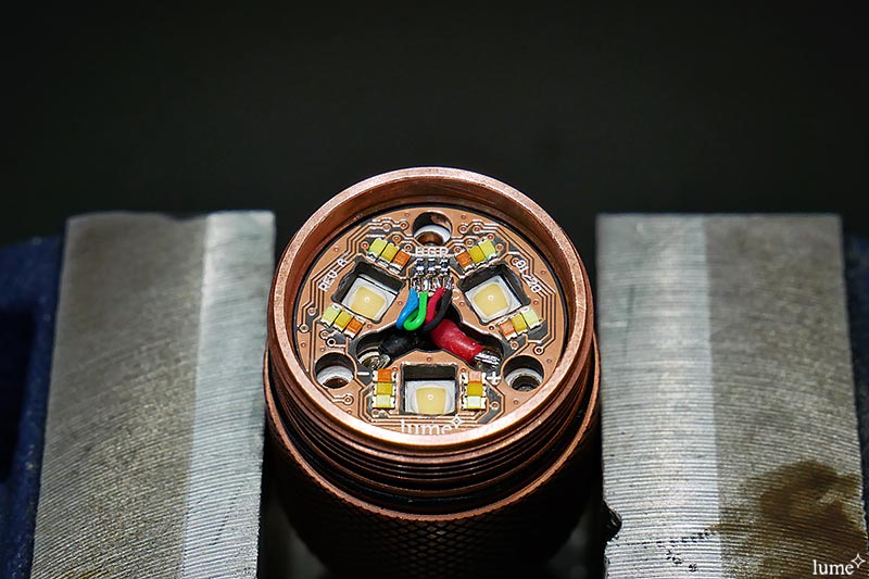
Above is the tri-LED board uses a total of 6 banks of RGB LEDs.
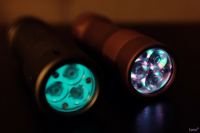
Here is the tri-LED board in action, compared the glow gasket of my FW21A. For the above photo, I used Cyan, Pink, and light green. I didn't really like how the green turned out, so I swapped them with warm white instead.
Above is the combination I settled on. I used 0603 LEDs because the 0402s I ordered had not yet arrived. You can obviously use any colour you want.
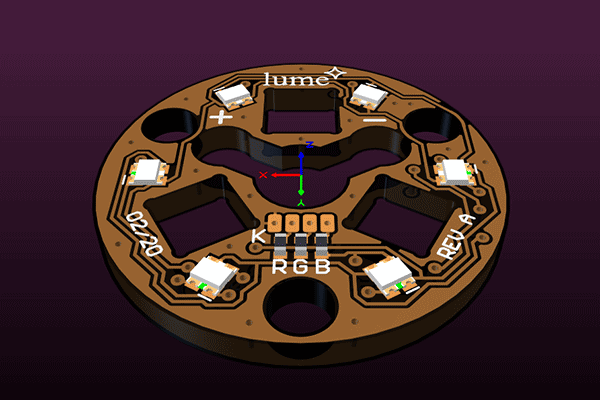
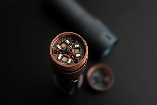
I also developed another 6-RGB-LED Aux board which uses size RGB leds, instead of 18 individual LEDs. These boards are available on OSHpark for anyone to build their own.
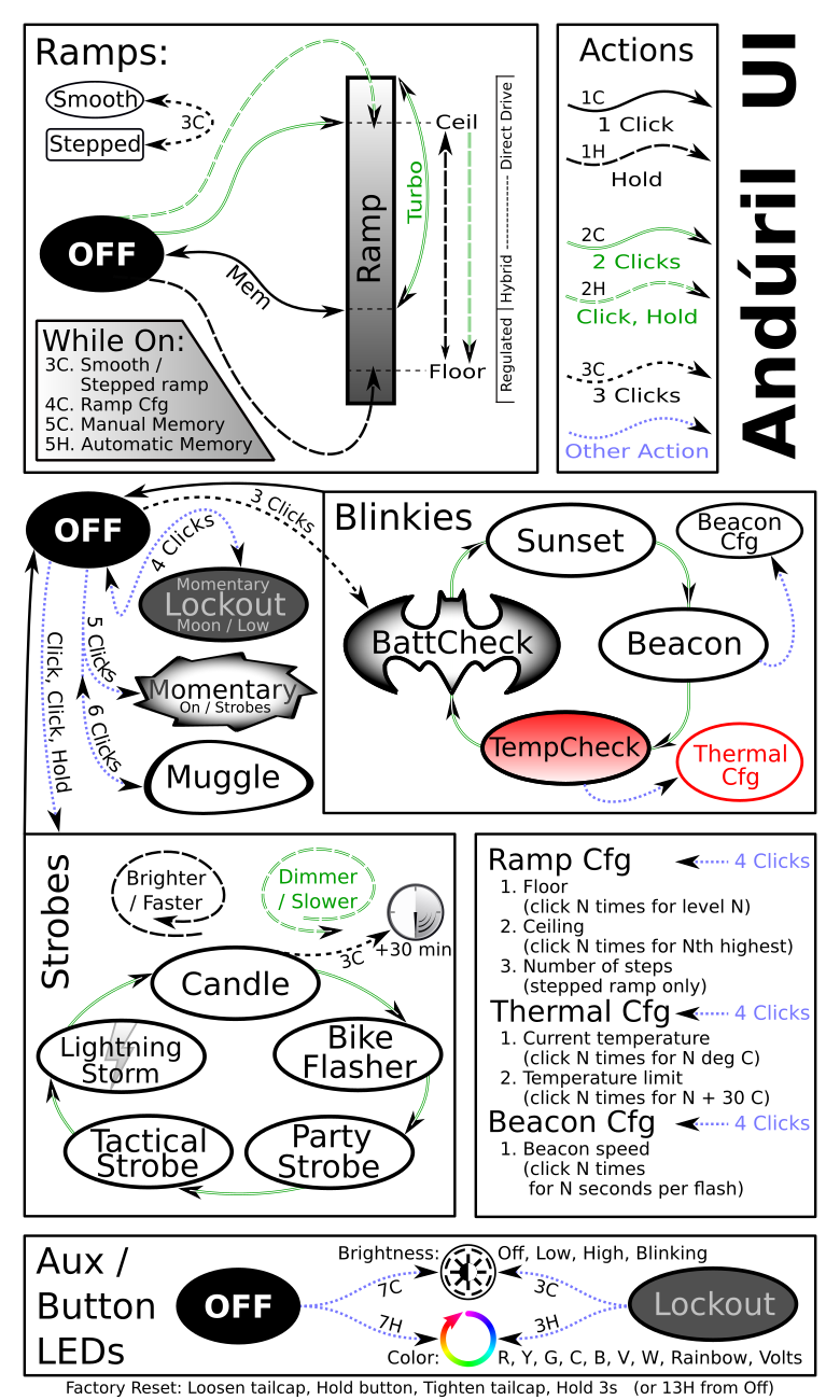
Anduril Firmware
With the support from ToyKeeper, I was able to get Anduril working on this flashlight. Fortunately ToyKeeper had already done a massive amount of work with Anduril and it had all sorts of capabilities built in to allow easy support of this driver. Since I work on a Windows machine, I used Atmel Studio for the firmware builds and flashing.
At this point, all functionalities of Anduril have ported to the lume1 driver. Some modifications were required.
All main functionality has been verified including:
- Ramping functionality (in this case, 1024 levels of brightness with 10-bit PWM, similar to Noctigon K1), all regulated with Buck Boost up to 3A
- Turbo with FET - PWM of FET is not recommended
- RGB aux LEDs verified working
- Standard strobe modes all working (candlelight, bicycle, party, tactical, and thunderstorm)
- Utility functions working (e.g. voltage reading, lockout modes, aux LED control etc)
- External temperature sensor verified working
There are still some functions on the lume1 board not taken advantage of yet:
- 4 solder jumper pads are connected to MCU but no firmware written to take advantage of them yet
Finally, I took a quick video to illustrate some of the basic functionalities so far (Rev A board):
")
Please keep in mind that video shows preliminary hardware and firmware, and work on it is still in progress.
Regardless, this one is shaping up to be my new go-to flashlight already. I'm also glad to say that there isn't any issue with noise from the switching regulator at all power levels.
Hopefully this will be a driver which people will find useful. 
Oddities of the lume1-fw3x Rev B driver
This is an in-progress list of quirks found during development process:
- Because of the Boost functionality, at very low battery voltages when battery is almost empty, maximum ramp brightness can be in fact, brighter than Turbo FET! Don't worry about battery draining to dangerously low levels thought - Anduril firmware handles low-battery quite well.
- There is no Reverse Polarity Protection - this was due to the fact that there were request to make the Turbo FET as bright as possible; adding a PFET for RPP would cause even lower performance. While personally I would like a RPP, I received feedback that people wanted to squeeze as much out of the driver as possible during Turbo. I will likely produce a V2 version with RPP and other feature in the future.
- Lowest moon mode is not as low as other 7135 systems - at the moment, it is a little brighter, but still usable. In fact, it is possible to reduce this even further, but the buck-boost goes into a pulse frequency modulated mode to save power / efficiency, and a flicker of about 100+Hz is visible. In fact, at lowest moon mode, a slight 'ripple' of around 1kHz is present. This can all be removed, at the cost of decreased efficiency at low modes, so I think the trade-off is OK. Any higher and output quickly smooths out.
- Max Turbo is done with a DD-FET, but the current path does go through the sense resistor, adding 20mR in the path. This reduces slightly the absolute max brightness. It's possible to 'fix' this with an additional FET to bypass the resistor, but I'm not sure if it's really worth the effort. This however can be beneficial for some kinds of lower V_fwd LEDs (marginally) like the Nichia 219, where Turbo had to be throttled to 50% duty cycle in the regular FW3A to prevent the LEDs from burning and turning blue.
- Factory Reset - work in progress; not possible like Emisar D4V2 since eSwitch is not connected when flashlight is unscrewed, and it uses a different MCU as FW3x (which uses ATtiny85), and not supported in Anduril yet.
(Now enabled thanks to ToyKeeper!) - Aux. LED driving voltage is 2.5V - a little lower than usual, and experimentation in required to decide the correct resistor value for the LED aux board. Blue LEDs for example, with high V_fwd will require a very low value resistor (such as 33 ohms).
I'll greatly appreciate any feedback and suggestions. Is this driver something you think would be useful, or completely useless?? I'd love to hear your thoughts. I know I'll be swapping out my FW3x drivers for this one though, since preliminary tests with my dev platform have gone quite well. Thanks for reading and I'll continue to post updates as this project progresses.
Finally, many thanks to all those in the community who have offered suggestions, feedback, ideas, and of course TK for her contributions to the community, without which this driver would not exist.
Thanks for reading!
Previously (now closed) group interest list - scroll to top for links to purchase your own: https://budgetlightforum.com/t/-/61834