helo
I will tell you exactely what I need
I have hand vacuum cleaner. https://cache.osta.ee/iv2/auctions/1_1_8495647.jpg
Originaly it has 3x1.2AA bateries in series. All the time charging it kiled batteries.
I take off the “charger” (few resistors, diode,…)
I decided to put inside only two 18650 (from old laptop) in paralel. And manualy charge the cleaner when it will be necesarly.
Now I need charging (not a problem) and low voltage protection board…the booard tp4056 seem perfect…but there is a problem current.
The motor take 6A constant current and 14A pick current.
How to modify the tp4056 board in the output that will pass this current?
relay??
change FET?
aditional FET??
Or connect motor directly to battery and use out from boart to some buzer or warning led (that the bateries has low voltage and need to charge)?
As I said before, connect the battery pack cathode to all of the boards B- pin inputs, and the vacuum cleaner's motor to all of the OUT- pins, minimizing and balancing path resistance(s). When the boards are in operation under normal circumstances, their FETs are closed conducting electricity, and current flows between OUT- and B-. Since you say the thing can draw up to 14A, you may want to use 6+ boards in parallel to minimize the chances of a FET cascade opening, as each FET is controlled by its own “brain” (DW01 chip) and, with just 5 boards (5 × 3A peak current flow), we may find the protection kicking in from time to time if we often get near those 14A and our current paths aren't perfectly balanced (shouldn't be much of a problem, though).
Connect the battery pack anode to the boards B+/OUT+ (its the same thing) pins, so all of the DW01 monitoring chips are powered. Only the boards getting input power at their IN+ pins will charge the battery(es). Edited and fixed.
That's right, svicar1. Still, I warn you to use no less than 5 boards, 5 × 8205A FETs. At 14A peak current flow, no less than 3,5A will try to flow on each FET and it'll trip the protection…
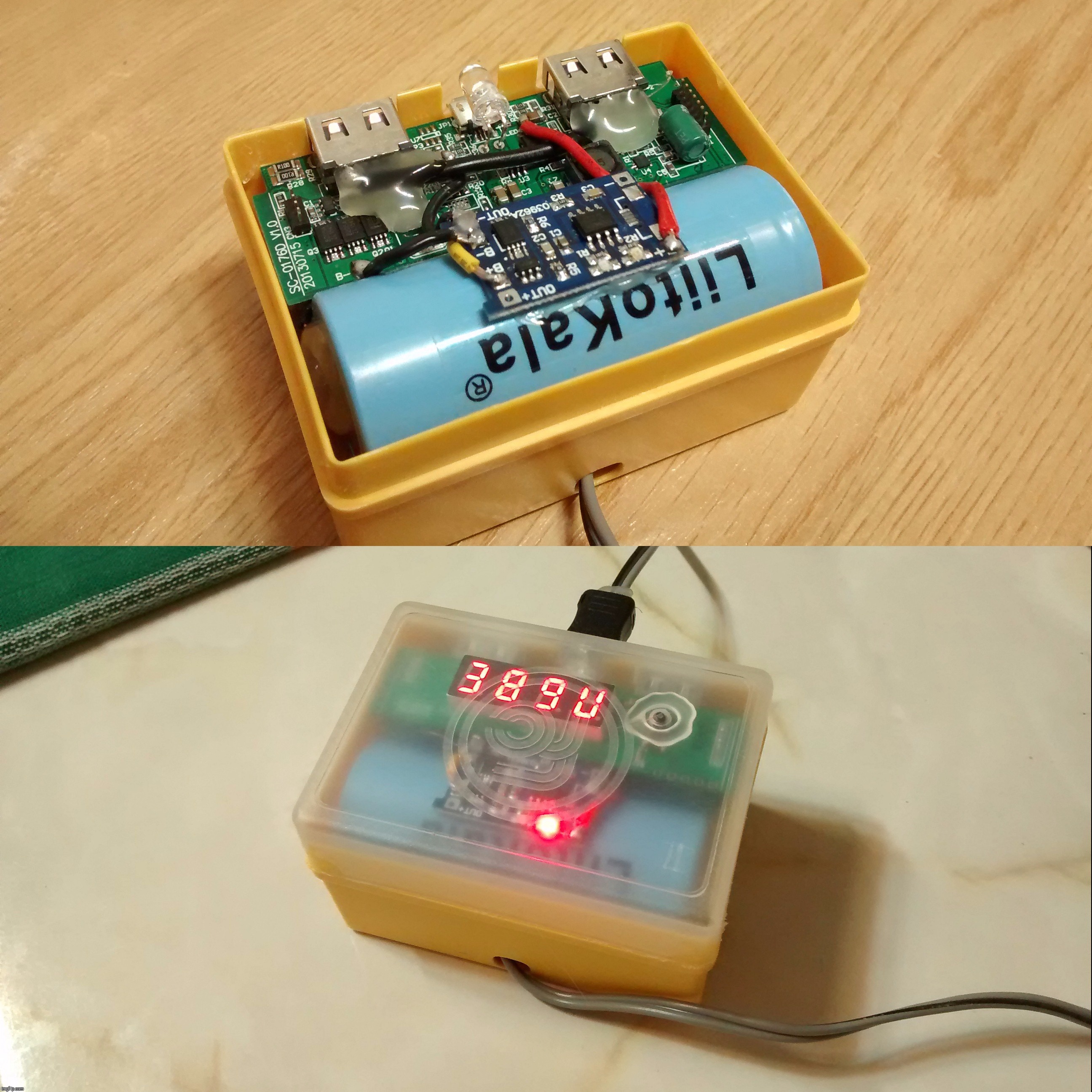
Also, you ought to know it is safe to use more than 1 charging board in parallel, even if your “charger” (PSU) isn't powerful enough (though don't blame me if you're using some sort of cheap knockoff). The boards just throttle themselves. Look at this pic:
Custom hand-crafted powerbank I made for a friend. That board uses a single TP4056 charging chip. After some analysis, I improved the charging engine with the addition of a TP4056 charging/protection board in parallel. His phone charger, a 1A unit, delivers up to 1,2A, but it hasn't burned out yet while feeding the powerbank (which now requests 1,7+A).
Cheers ^:)
P.S.: Relay? No, thanks. Those FETs do such a task very well already. Modern solid state relays are made with FETs. ;-)
Need help to resolve the problem while using this tp4056 with protection charger. In my circuit I have taken the ground of protected circuit to my circuit. I am not getting the voltage when I give the input what is happening when I shorted the battery ground and protected circuit ground then only I am getting the voltage will it cause any problem to my battery. I am very confused and in danger zone will it charge if I short both the grounds
1) “In my circuit I have taken the ground of protected circuit to my circuit. …”
What are you calling “circuit”? I see such word mentioned 3 times in your first sentence, and it seems to me each one refers to a different subject. Let me try to clarify reword it: “In my TP4056 board I have connected OUT- to load circuit. …” This is just a guess, and let me explain something: OUT- = IN-, OUT+ = B+.
2) “… I am not getting the voltage when I give the input what is happening…”
Dafuq? What voltage?Should I presume some sort of cell is connected somewhere? There's also no mention of how the load circuit is being (!) powered.
3) “… when I shorted the battery ground and protected circuit ground then only I am getting the voltage will it cause any problem to my battery. …”
I believe this should be rephrased into “… only when I short B- and OUT- load circuit gets voltage, will it cause any problem to my battery? …”
Looks like the protection is triggered by the load :???: circuit. This can happen with ≈5A of draw or less, as a single 8205A MOSFET is rated for just up to ≈2.5A continuous (typical 8205A's RDS(ON) is slightly below 30mΩ when at ambient temperature, while the typical DW01A detection voltage is ≈0.15V).
4) “… I am very confused and in danger zone will it charge if I short both the grounds”
You just bypassed the protection circuitry. If your load circuit cannot overload or overdischarge :???: the battery, I see no problem and the thing runs a little less dampened.
I will clear everythung. Actually I am using this tp4056 to charge my battery through solar. I connected battery to B+ and B- taking output from OUT+ and OUT- but I am getting only 1.2v (battery is fully charged LI-ION 3.6v 2600mah battery)
Why I am not getting the voltage. I shorted B- and OUT- to get the desired voltage
I have a Suboos 2x18650 hanging camp lantern that is a very handy design save for its UI and emitter choices. So it’s basically a host.
Considering replacing the driver and charging circuit and was wondering if this board would be acceptable for charging 2 cells in parallel?
a bit late but yes.
i have a 70’s table lamp i converted with 12p 18650.
at 1a into about 28ah it takes a while.
i jb weld epoxied a small heatsink to the board to help with thermal throttling.
esp since the solar panels output at 1a load in full sun approaches 6v.
The circuit does not help against reverse polarity (which would be useful) but against overcharge, overdischarge and overcurrent.
Really I fail to see what use would that protection have in a charger (which is supposed to terminate, to not short and never discharges). But these circuits are there for some reason so I likely miss something.
Agro that isn't hard to figure out. By integrating protective circuitry the board can also prevent over-discharge and etc., so it can be easier to li-ion convert something.
Ah, I see.
I used to view the boards as just chargers that lack cases rather than parts of other devices. Even though I’ve seen them used in flashlights.
After all, it is likely to use 2 or 3 charging boards per input connector. So, you don't really need that much type-C TP4056 boards or socket boards (which they're asking more money for).
Agro, if battery reverse polarity protection is important for you, try with TP5000 boards (datasheet).
Quite more expensive than TP4056 boards and they come without any socket, but can be found stock configured for 2A charging (with heatsink). Example: https://www.aliexpress.com/item/-/32886711330.html
Thanks Barkuti. I’m actually looking into 50-100 mA range.
My cottonpickers charger starts failing and frequently stops the charge way too early.
Furthermore a few times I wished I could give sb. a 10180 charger.
And as of now I just don’t have anything around 100mA.
So…a few uses. Add magnetic leads, swap a resistor and TP4056 is ready to roll.
I was just worried that those boards may not be particularly good…
Reverse polarity protection would be nice. Myself I’m not infallable and I’d lije to be zble to give the boards to muggles. I need to look closer at that TP5000 when I’m bach home, maybe there are boards with usb ports…
a bit late but the boards should just shut off if overloaded.
if they are being killed its probably from the inductive kick from your motor.
a reverse biased diode across the 4056 board output might protect it.
note that while you measure 6a running it may pull a lot more at turn on.
protection responds and the load dump from the motor nukes the board.
According to the NanJing Top Power datasheet TP4056's termination voltage is fixed. An easy method is to set one or more schottky diodes between the battery and the charger module, this will drop termination voltage by the schottky diodes' Vdrop at the given cut-off current (around 0.25V more or less).
I advice you to first measure the TP4056 module's termination voltage. Power it on without load and measure it with a voltmeter. A couple modules I have lying around measured at 4.11 - 4.12V.
I also have some on the way. Having both type-C and micro-B modules let me equip my li-ion powered stuff with dual inputs for more flexibility. :-)


 What voltage? Should I presume some sort of cell is connected somewhere? There's also no mention of how the load circuit is being (!) powered.