Damn, never mad so many short circuit in my life until I started experimenting with this lights for switches.
I installed one in new C8 (clear one, with new driver), used 3 channel board and 3 x 220 ohms resistors, no modification on the driver. I must have done something wrong because it behaves unpredictably, sometimes works OK, light up nicely, when I turn on the flashlight tailcap lights turn off, when switch is in off position tailcap lights are ON… but sometimes just doesn’t work no light from tailcap and no light from flashlight main LED! this is harder than it looks
If the main light no longer works then it’s probably not the lighted “daughter” board to blame. Is the switch getting good ground to the tailcap body through the retaining ring?
One other thing to try:. When I’ve got one being ornery I wrap the whole outer edge in kapton tape, just don’t let it wrap under the bottom and insulate the ground contact.
If y’all weren’t aware, Texas Ace has a few tailcaps for sale as add-ons when you buy one of his drivers. He is doing them all pre-calibrated to work with the driver, all you would have to do is fit them in your light and adjust the pot with a screwdriver to your desired brightness.
I am also putting together a spreadsheet with different resistance / current measurements from various color LED’s. I will post it once I get the last few colors tested (got to wait for more PCB’s to show up).
I will be installing some fixed resisters in addition to the pot in order to limit current to what the driver will be happy with on the ones I build. Not 100% fool proof but should vastly reduce possible issues.
I will answer here to encourage asking questions here. I just happened to see your thread, but if you post here I get an email notification (as do others who can help when I am busy).
The S41 uses a different driver that was not made for the illuminated tailcap. You will probably notice that the modes on your light don’t work correctly when you turn it off either. You need to add a bleeder resistor to your driver. This information is in the first post
I don’t expect you to read this whole thread, but I’d say please read the OP, and maybe the most recent two pages of comments. Even if you don’t, please ask any questions you have. You’ll normally get an answer more quickly here.
wait, what, why the bleeder resistor is 500-800ohm, it should be some K ohm, so that the led in tail cap don’t need another resistor( i disassemble 1 tail cap, and it has another resisor to limit the current)
This is not my design and I don’t claim to fully understand it all, but I don’t think that’s how it works. You really need the two different levels of resistance — a low resistance path so that the OTC can bleed off quickly preserving the timing of the mcu, plus a higher resistance path to dim the tailcap lights sufficiently.
Finally got around to trying this again, now that my new soldering iron came in. Overall, it went pretty smoothly. But it could have went a lot smoother if I had read more carefully.
Target: Convoy S2 with a nanjg105d 2.8A driver Switchboard: stock Convoy Illum. tailcap board: Rev5.3 (top) LEDs: 6x blue 0805 Tailcap resistor: single 10K ohm (bridged the two channels) Bleeder resistor: 750 ohm Measured draw: 0.1 mA (my multimeter only reads tenths)
One difficulty: the nanjg105d didn’t have a good place (that I could see) to solder the bleeder to. I ended up soldering one side to the spring and the other side to the outside ring via a jumper wire.
Other difficulty: instead of starting out with a 10K ohm tailcap resistor, I used a 10 ohm. It was obviously too bright and the driver wasn’t working right, so I tried a 30 ohm. And then a 100 ohm. And then I finally re-read some posts and realized I should have been using a 10*K* ohm resistor. Once I put that in place, everything started working like it should. I might even try a 20K ohm next time, but I didn’t feel like opening everything back up on this one.
One other thing: the opening in the ring wasn’t quite big enough to seat onto the switch properly. So I lightly filed the switch casing. I could’ve opened the ring’s hole a bit, but the clearances seemed tight.
Thank you PD and everyone that has contributed to this thread!
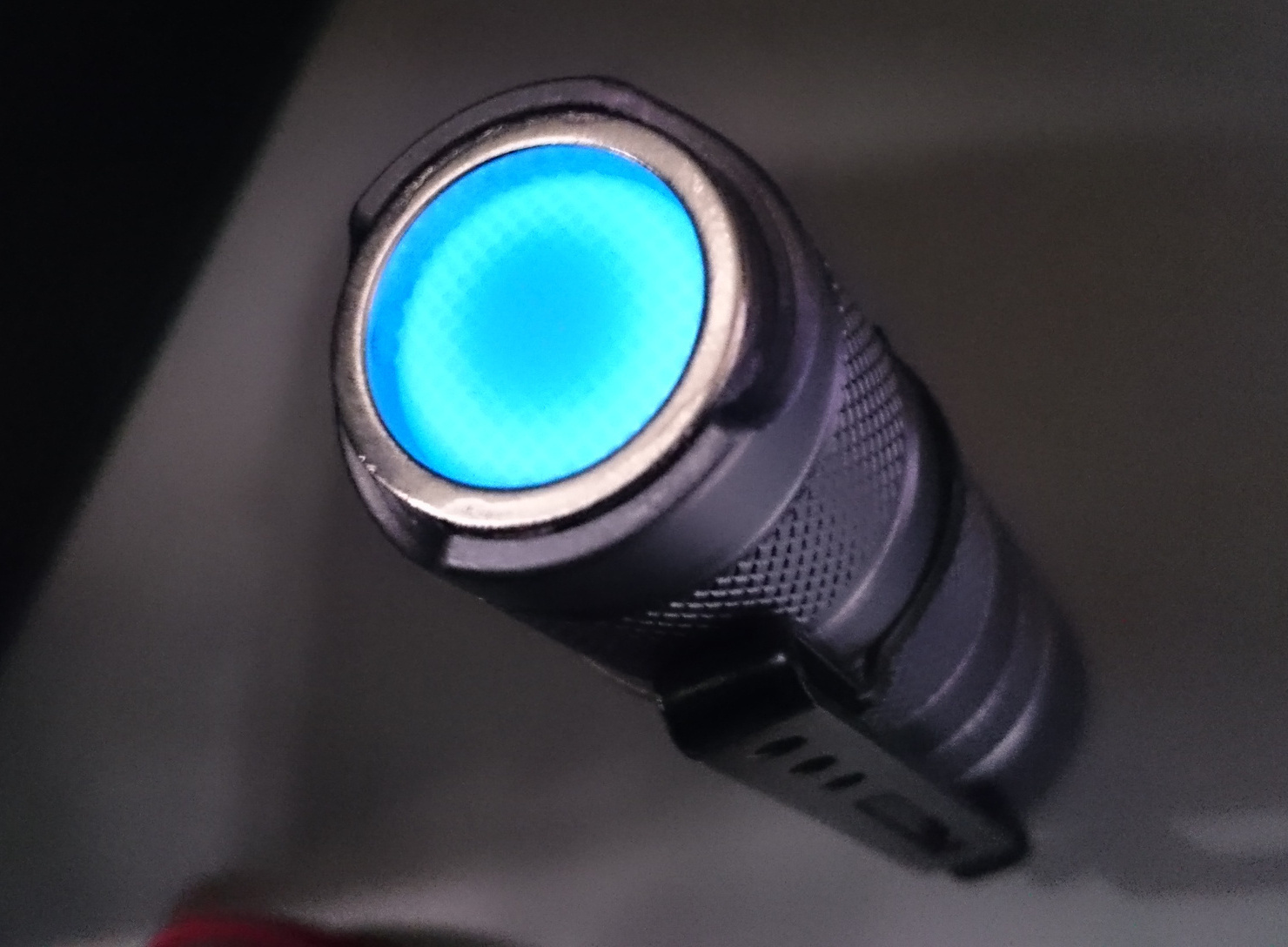
I changed the tailcap lighting in my S2+ shorty and the switch boot. Earlier it has clear switch boot and green leds under it. Now it has a light blue rubber boot from Simon’s aliexpress shop and white leds under it on PD68 V5.1 Lighted tail switch board. Now it has the nice light blue color what I wanted.