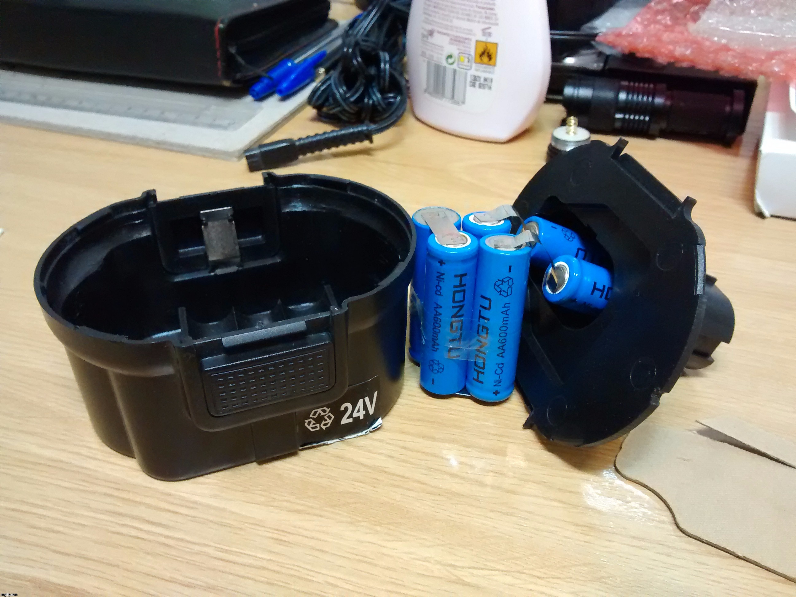
snakebite, my BMS choices have been influenced on a tad off-topic handful of posts brief discussion I had a few days earlier about restoring a Hilti TE 10A hammer drill power source.
Briefing: 1.2 - 1.4Ah sub-Cs, operating at up to 15A (≈10C cells).
… it more or less becomes clear to me that not even in their wettest dreams would have those AA Ni-CDs provided more than around 8A comfortably. Bottom line: the appliance was a piss-poor electric screwdriver, to start with.
Yesterday I sent inquiries about that inexpensive 15A BMS from Aliexpress to two sellers, asking for the transient/momentaneous operating current values on it. After receiving the same useless copy/pasted answer/information in both cases, already provided in the product ads anyway, I've decided to go with the eBay 15A BMS which, being like the 8A (17A transient current) unit with twice the FETs, I presume its transient current value should also be 2 × 17A = 34A. :THUMBS-UP:
Evaluated ImA4Wheelr's #18 post suggestion regarding those 1-8S li-ion voltage monitors (found 'em on eBay from $1.17), but heck, the stuff is gonna have a proper BMS taking care of independent cell monitoring sooo keep it simple stupid.
you might be surprised at the start surge on that motor.
get your shunt and scope out and have a look.
i would use the bms to charge but not run the motor from it.
it will trip every time you pull the trigger unless that motor is a total wimp.
which is entirely possible knowing what that drill is.
In the eBay ad the BMS board is said to have been tested on a Bosch GSR 7.2 succesfully.
I was also thinking about this but, maybe I could order one of the cheap Aliexpress 15A BMSes and set it in parallel with the one I ordered. Of course, the predicted slight differences in BMS resistances means that the inter-BMS load distribution would differ, but nothing excessive I think. Even if one of them only channels half the current the other does, we would still be at a 22-23A continuous and probably twice that figure for transient current. Shouldn't be very hard to measure load distribution…
My best bet for now, I believe, is to wait for the ordered BMS and take a look at the markings on its MOSFETs. If it ends up needing some current handling improvement, it'd easy to add up to 4 additional ICs stacked upon the ones onboard.
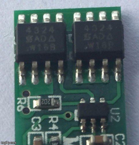
Just checked out eBay, plenty of SOP-8 MOSFET 5-packs for under $1. I wish I were to have a way to know what model does that board uses.
Mmm, been searching for “2S BMS” images on Gmail search but, to my dismay, barely any of them were useful with regards to peeking at their SOP-8 MOSFET IC markings. Most pictures lack detail/resolution and/or their chip markings are “sabotaged”. Could read AO4119 in a couple of unrelated, scant examples.
Mmm, just wanted to save some days by ordering an additional MOSFET pack right now. LoL!
Well, you could save some time, but pay for it in cash, by buying enough MOSFETs to replace the existing ones as well. Then you know you’ve got all good ones on the board.
Mmmkay, not an expert on these matters DavidEF. According to what I've briefly read about MOSFETs, their resistance (RDS(ON) I presume) increases with temperature so they share the load efficiently (current proportionally diverts to the lesser resistance gates).
The important question here is that the circuit is designed to use either N or P-channel MOSFETs, and I don't have a clue about this (literally).
With regards to nice offers there are plenty, a 5-pack of AO4409s for under $1 or a 10-pack for $1.36 sounds great, with just ≈9.5mΩ typical RDS(ON) at VGS = -4.5V and ID = -10A (P-channel MOSFET), so 4-5A of continuous current handling with ease even if cooling sucks. I have nearly a dozen DIP-8 MOSFET datasheets on my document viewer atm LoL.
Already modding before the first outing, where have I seen this before?
Asked the eBay seller what kind of MOSFETs are found on the 8/15A balance BMS boards, though I'd be surprised if the answer is other than “WTF?” or similar.
Stray capacitance issues? I'll need to use around 3" of wire up and down inside the battery compartment, hope 4×AWG18 current highway width does nice enough. I'll also take a peek inside the screwdriver/drill, just in case.
And with regards to the still yet to know current handling problem, seems the Si4324 isn't so dirt cheap as AO4409s, yet I see it offered for $0.31/piece plus $1.26 of shipping for up to 10 units in Aliexpress. So ≈$2 should “make my day” if this ends up being an issue.
motors are an inductive load.they produce spikes.
and your aliexpress parts may turn out to be fakes.
pretty common to fake whatever is in high demand and expensive or in short supply.
like the 30f131 igbt.
i use a lot of them to repair panasonic plasma sc and ss boards.
if you got fakes you will know as soon as you turn it on when it goes BANG!
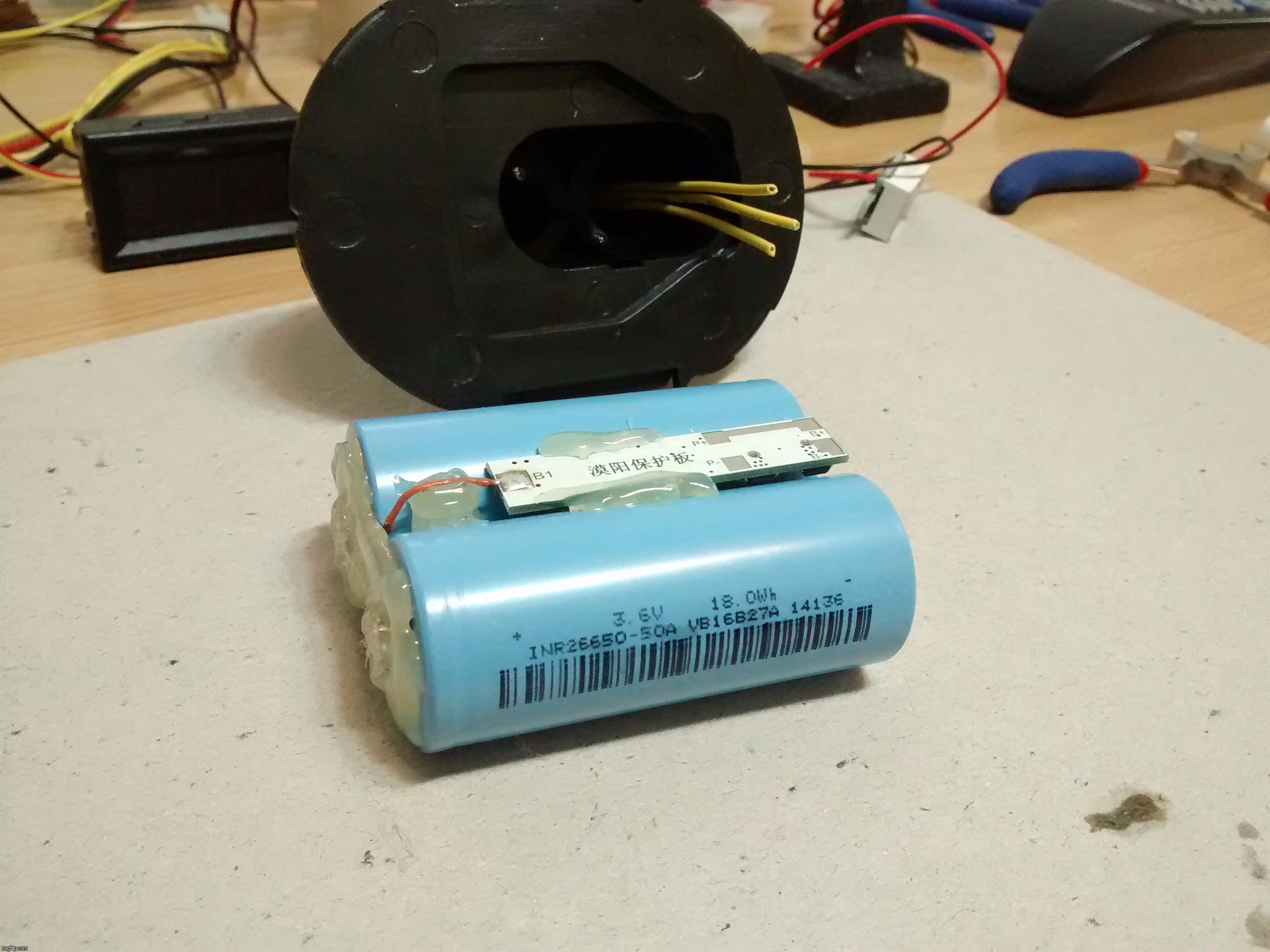
Getting somewhere lately, the parts arrived recently. My ancient 26W soldering iron, with all those thick, packed wires tuck over aluminium pads made with 25 fold wide alu foil plus plenty of FTKA/F61A, is barely making it. Got the catode side done but, the anode… :facepalm:
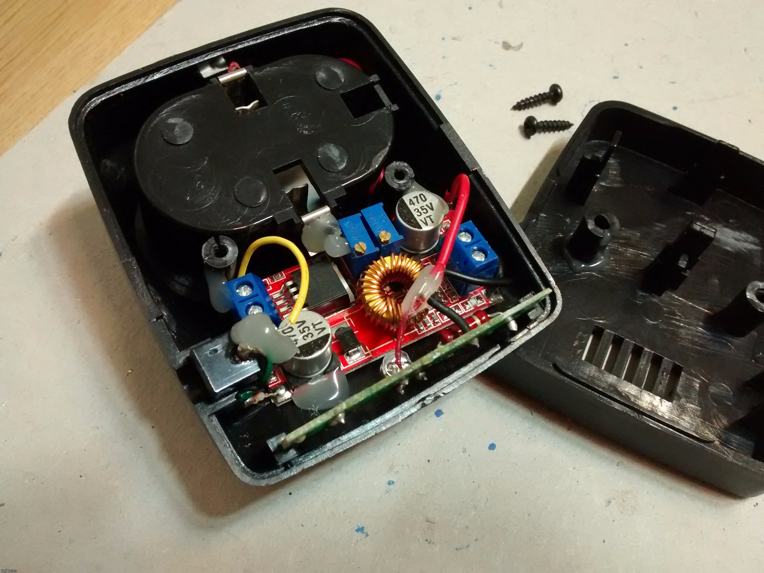
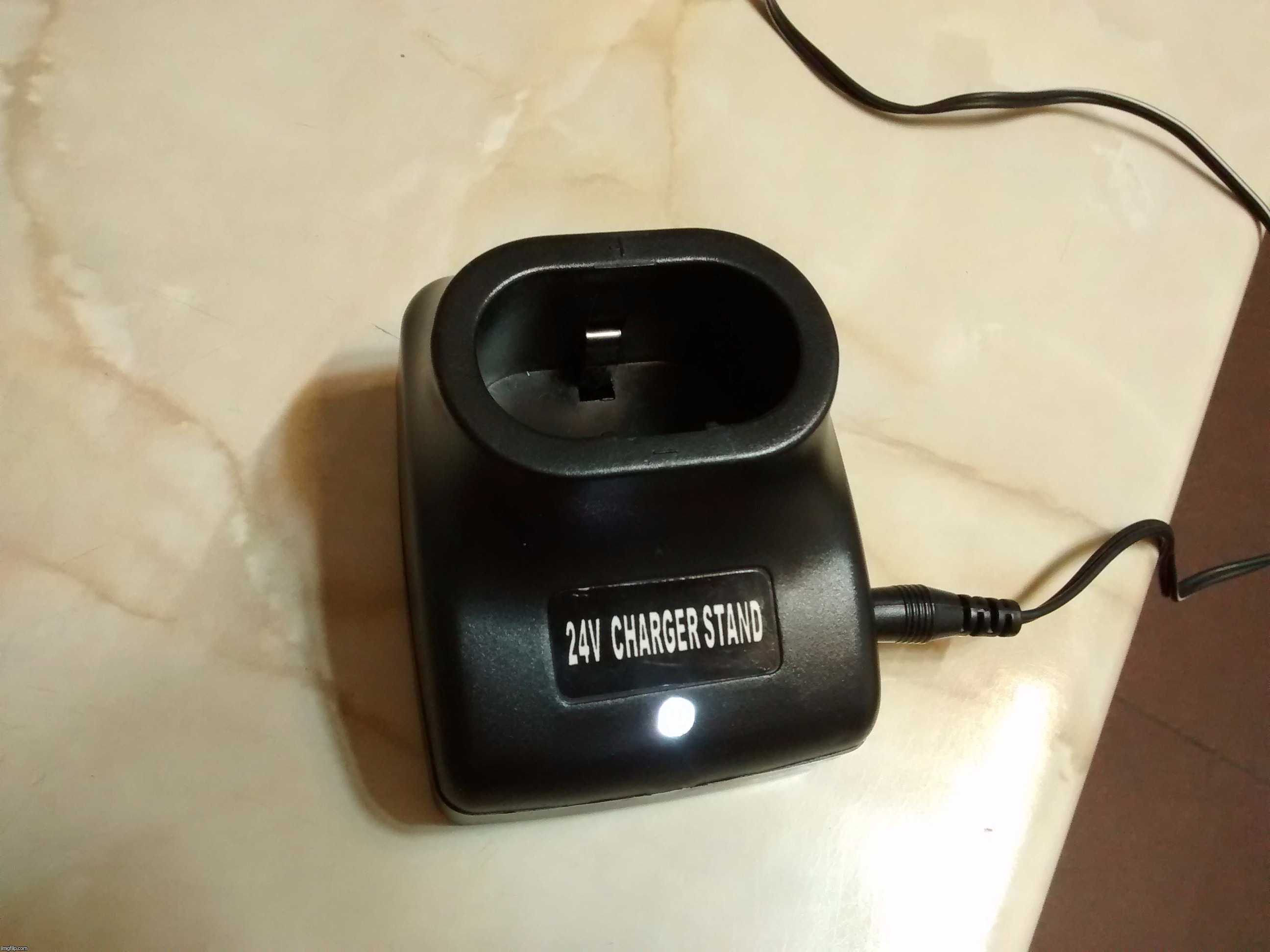
The charger stand now has some real technology inside.
A white led instead of its former old, boring and inefficient red one.
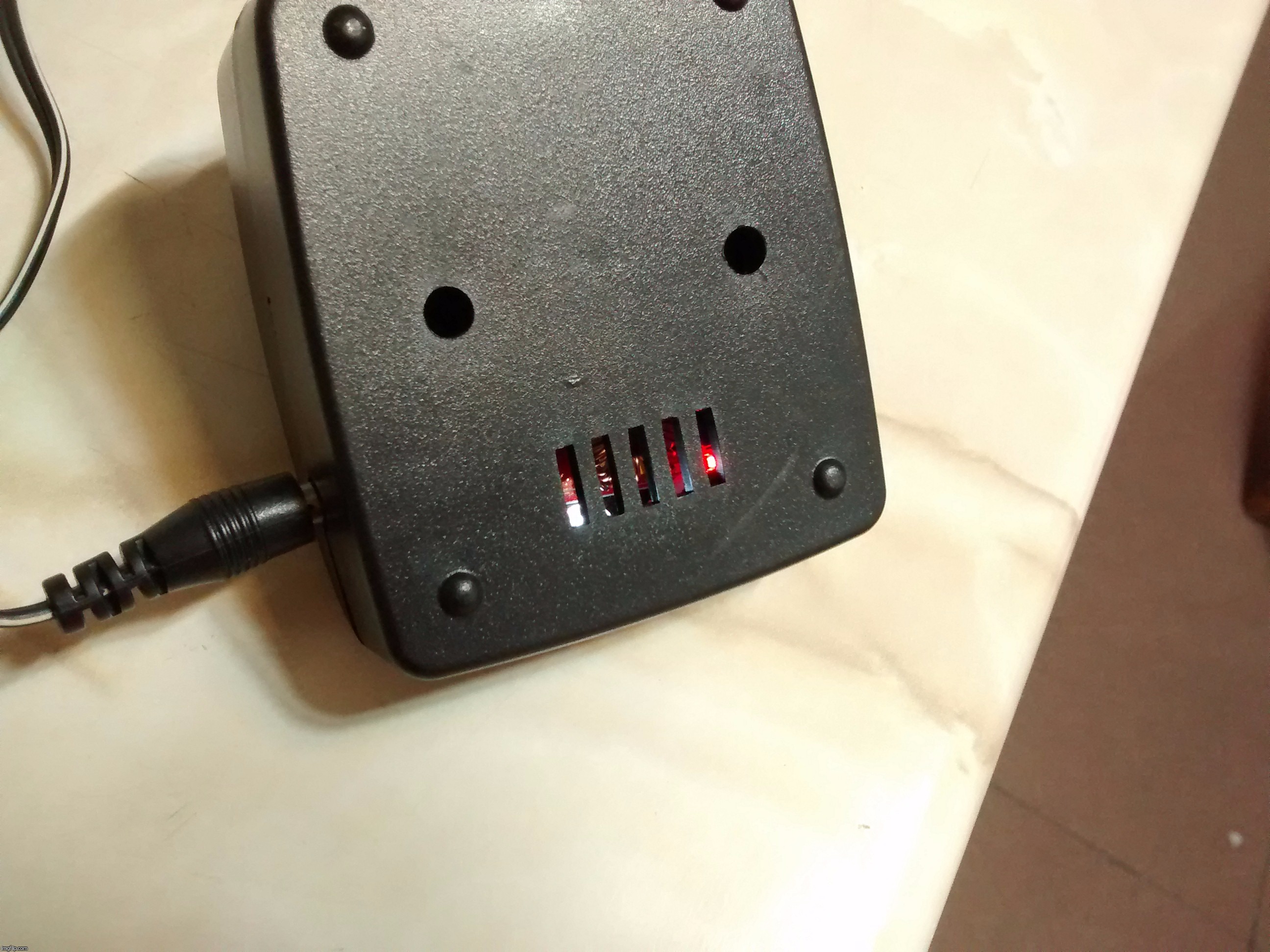
That little plastic lattice from below allows to peek at the board's status leds.
Tuned the board to ≈350mA of current output (the power led sinks ≈5mA from it), that's the most I've considered safe considering the adapter only provides ≈3.3W (11+V, 300mA).
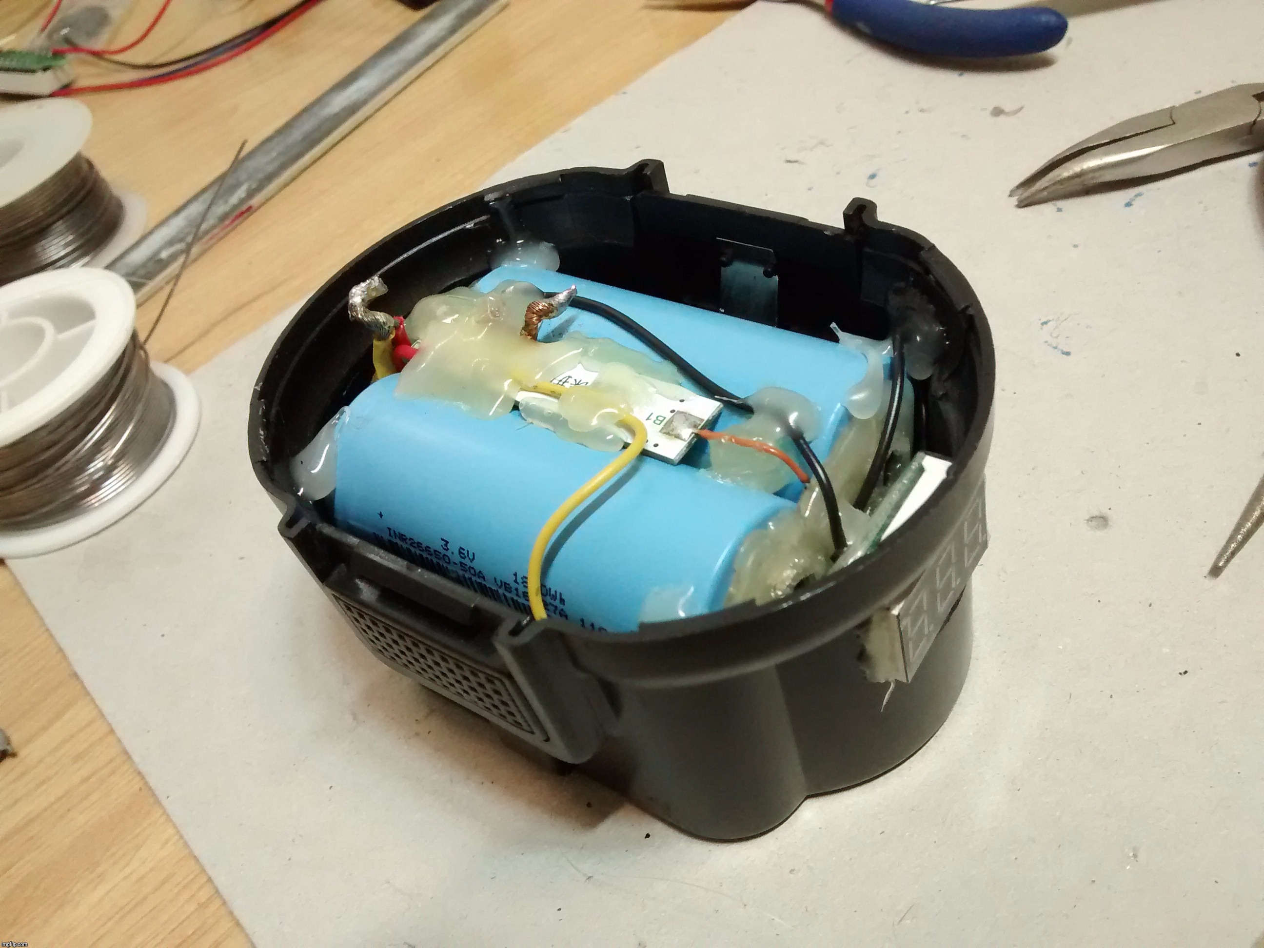
The pack is nearly done too, I'll carve a little window for the voltmeter on its basket tomorrow, let's see if I can finish it. More pics coming soon.
Well, finished the whole shebang a lil while ago. The voltmeter is activated by pressing over it, as the switch lies just behind its PCB, glued over the batteries. Overall feel pretty satisfied with the thing, as it's been a tight squeeze inside and I've managed to glue the batteries at the right distance for it to work nicely. The hot glue at the sides of the voltmeter outside of the tray makes it hard to press the thing, good because it draws nearly 20mA while in operation, makes it hard to leave the thing involuntarily activated.
Gonna test it tonight, my friend's coming home to see the demo and provide party sweets… :BEER: :UGHH: :BLUSH: :CROWN:
Well, I'm quite satisfied with the tests, my friend quite likes it! The overcurrent protection trips a bit soon, though. I mean, as a drill, you have to be carerul as to avoid too harsh of a start-up or any other over-torque situations. As snakebite said, the overcurrent protection tends to trip a bit early.
I'll stack 3 additional chips over what the 4 it has now, should suffice for ≈28A continuous, 59.5A peak. Mmm, or maybe just 2, 24A continuous, 51A peak. LoL!