They were XM-L2’s that died, but when I reported it I realized that it wasn’t just me, U3’s were dying for everyone. So I was wondering if there is a similar “cursed” bin of XP-L’s
It’s not the size of the emitter that matters, it is the size of the aperture of the flashlight.
I actually didn’t know how the website algorithm worked, so I took out my trusty calculator and did some simple trig, and I did get the same value as the website.
Basically imagine a triangle, starts at one point, and at 10m has a spot that is 10cm.
That is far more divergence than a rhombus that starts at 5cm and at 10m has a 10cm spot. (which is a section of a much looonger triangle)
As you can see, the second case has a lot less divergence than the first.
The square law of light “calculate back to 1m” method works for case 1 but not case 2.
I will draw a pic later today to illustrate this for other people
Well according to that calculator the beam size and the aperture are what matters. The beam size is determined in part by the emitter size (they are roughly proportional).
I agree with what you say, but I think the calculator is not completely right, for the reason I explained above. Imagine you have your lens, but you can switch between two different sized emitters. The two emitters will make different sized beams (measured at whatever distance), and so that calculator would predict different “divergence distance behind aperture” for each emitter. I am arguing that this is not accurate; they should have the same “divergence distance behind aperture”.
My measurements showed that this distance is the same for different sized emitters, and I think this makes sense. Imagine having one emitter, then putting another emitter right next to it to effectively double its size (in one dimension). Nothing has physically changed about that first emitter, but the calculator predicts a significantly different “divergence distance behind aperture” value. I think that is not physically accurate.
The calculator is essentially using two data points to draw a line to calculate this distance, the beam size at the aperture (which it assumes is the same size as the aperture) and the beam size that you actually measure at some distance away. The way I calculated the distance is by actually measuring the beam size at 3 different distances and drawing the line. I get a different result than the calculator; the effective beam size at the aperture is not actually the width of the aperture. More measurements are needed to fully understand this.
Thanks RBD,
2AM project… hope it works.
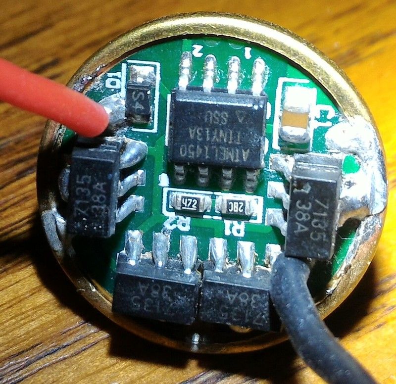
With that said I did something stupid. Hooked to Bench PSU with reversed polarity. It’s from a Thorfire BD 04 and the driver is build different (wrong, backward).
Original emitter is dead so, will see shortly if driver survived.
Very pretty solder work, and not an easy thing to do. At least, its not easy for me to do
If you want to save a bit of time and effort, next time skip the center pins. Its continuous with the ground tab in the back so as long as one of those is connected it’ll all work fine.
And in most cases the base level center pads aren’t connected to the ground ring anyway so the only possible benefit is a smidge more heat sinking from the added solder mass.
The emitter size is what affects the divergence.
If it was a point source, the rays would be collimated and the spot size would be equal to the projected size at any distance, which results in an infinite candlepower.
If you use the calculator and put the same aperture and spot size you get a divide by 0 error.
Since an LED is not a point source, the spot at 10m is larger than the aperture, which means there is divergence, and that is what needs to be taken into account.
And “aperture” refers to the initial diameter of the beam when leaving the flashlight. So the beam size is literally another way of saying aperture.
Obviously if you have a huge lens and only use 2cm diameter of it you would put 2cm as the aperture, not 200cm or whatever.
It really depends on how well your flashlight can collimate, this method is almost irrelevant for regular reflector LED flashlights.
I made a separate post to explain everything: The proper way of calculating lux / cd / candlepower