I put together one of the 15mm V3 boards today. It’s currently running in a SK68 with a $1.68 XPG3 from Arrow Electronics. I’m very happy with the light considering the minimal cost. I went with the standard thickness boards(1.6mm?) and didn’t have much trouble getting the driver to press fit. Thanks for all the hard work HQ.
thanks for the feedback, I’m happy and proud to hear you got it working. I was extremely busy the last weeks, so I couldn’t respond earlier. But I’m really curious about the following:
Where did you source the PAM2803?
How many capacitors did you use, which ones (µF) and where?
Which firmware did you use? Anything to share, perhaps?
How did the soldering work out, any places with too little space?
It would be especially awesome if it ends in a ~5 dollar china-produced finished 15mm driver with pretty configurable software, similar to the BLF-A6. That will make it available to a much larger public. But I must admit I see no easy route to get it that far.
Perhaps Banggood is interested if this driver as part of a to-be-designed BLF-AA flashlight. If this project is taking place sometime, I vote for a compact zoomie.
I’d buy them
But the 15mm version is so tight that I doubt it can be reliably produced in numbers. I still consider an MMU version an option, but that can not be re-programmed.
Sorry to disappoint you HJ, but I didn’t add anything to your work. Apart from the BAT60 and an additional 10µF cap all the components were swapped from the fasttech driver. I just used minidrv with 2 modes.
I actually assembled a second one as well, and felt the component spacing was very good. Not really any harder to assemble than some of the fet+1 drivers.
Question for the driver ninjas around here: does a guy with average skill have any chance of building the 15mm driver with a soldering iron or stovetop reflow? I can do lots of cursing if it helps
If not, what about the 17mm ? I’ve been thinking about a 4/3AF NiMH light for a while to leave in the car.
Soldering iron, I’d not dare on these.
Most parts of these boards are not stock eagle parts. I made almost all of them smaller, so they still work for a reworking station, but you have not much space for an iron. The MCU will already be difficult. The PAM2803 is so tightly surrounded that you will probably bridge where you don’t want to even with a 0.8mm tip. The pads of the inductor are hardly protruding at all, just so much that you can see if the solder melted.
Stove should work pretty well.
I haven’t done it with a driver board, but I reflow emitters on a regular basis with a stove, a very small teflon pan, a sliiiight oil film, this solder paste and pliers. As these boost driver boards are single sided, that should work pretty well. Just be gentle with the heat, don’t use the stovetop directly without a pan, and try the solder paste on empty boards first to get a feeling how much heat you need before you fry some precious parts.
But if you got 40some bucks to spare, a Youyue 858d+ is really worth it and can be used for easy desoldering and building double sided drivers as well.
What’s the purpose of the oil film? Heat transfer? I’ve done one triple in an old teflon pan so far and it went fairly well so I’ll probably try that first. I really don’t need one more tool to put away. At least not until I can make more space.
On second thought I would not use oil with the driver boards. It might get sucked up through the vias and could mess with the solder paste.
But for LEDs on MCPCBs, yes, it helps heat transfer. So even with an electrical plate I found it easier to regulate the heat to come at least close to the intended thermal profile for reflow soldering.
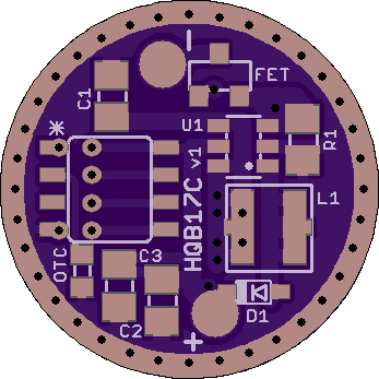
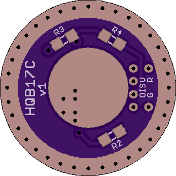
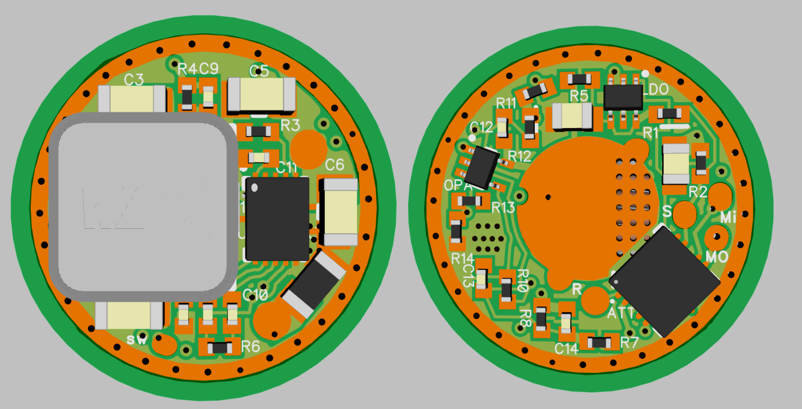
The arrival of the Convoy T2 revived my interest and I shared 2 new drivers, the HQB17C and the HQB17D, that are made specifically with the T2 in mind. Both are 17mm boost drivers.
.
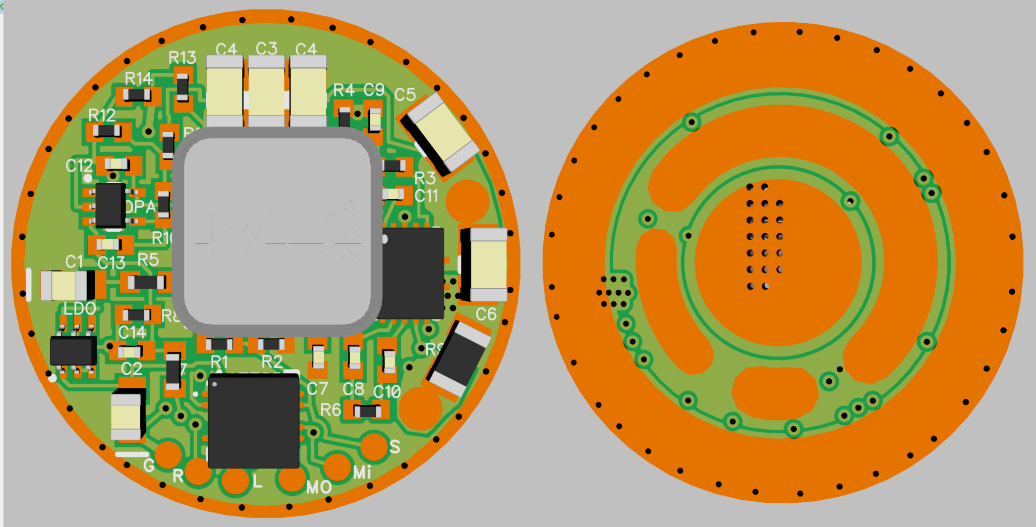
This is the ‘classic’ version, with SOT23 mosfet and up to 4.3mm inductor. There’s enough space for a SOIC clamp to program the Attiny.
There a some design changes to prior versions.
The driver features vias for a programming key, to allow true ISP.
I added a gate resistor (R4) between Pin6 and gate, can’t hurt to have one.
All 3 resistors went onto the spring side, that allowed to make the connection between PAM pin5 and LED+ without vias. That way the complete boost circuit is on one side of the board. The BAT+ pad is still 8mm, that’s ample space.
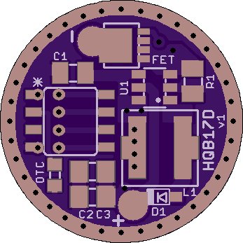
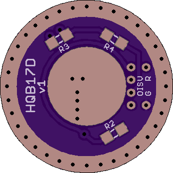
The arrival of the Convoy T2 revived my interest and I shared 2 new drivers, the HQB17C and the HQB17D, that are made specifically with the T2 in mind. Both are 17mm boost drivers.
.
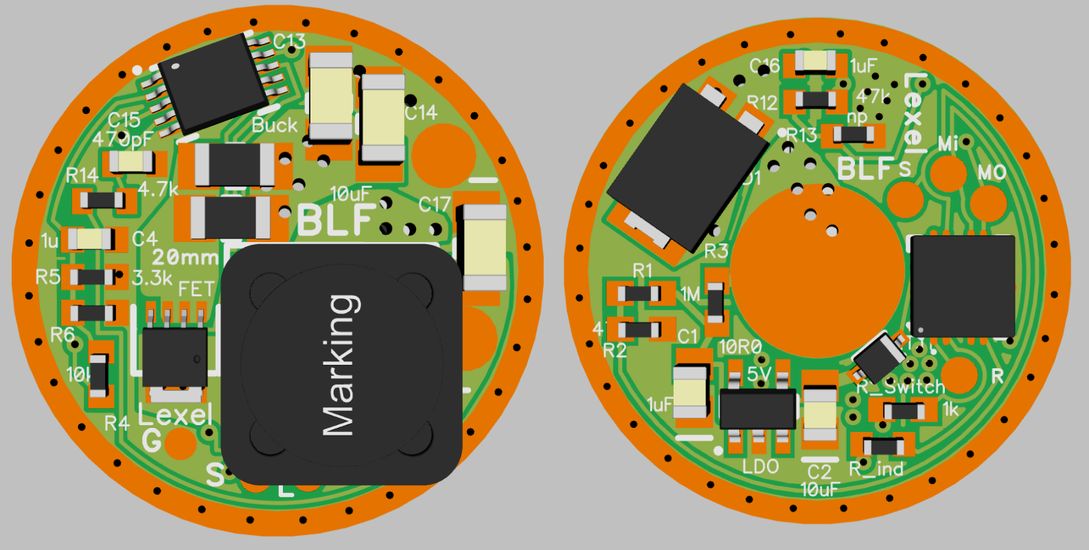
This is the ‘deluxe’ version with all the bells and whistles: LFPAK33 mosfet and up to 5.6mm inductor. Together with the BAT60A this should make a very efficient driver. Here, of course, a programming key is imperative.
There a some design changes to prior versions.
The driver features vias for a programming key, to allow true ISP.
I added a gate resistor (R4) between Pin6 and gate, can’t hurt to have one.
All 3 resistors went onto the spring side, that allowed to make the connection between PAM pin5 and LED+ without vias. That way the complete boost circuit is on one side of the board. The BAT+ pad is still 8mm, that’s ample space.
As mosfet I will use the NXP PSMN2R4-30MLD, that has an Rdson of ~3.2mOhm, in contrast to the ~27mOhm of the (already good) IRLML.
The inductor footprint is custom made with two inductors in mind: The Coilcraft XFL5030 and the Wurth 744316220. Both will fit and have an Rdc of ~11mOhm, in contrast to ~30-50mOhm of usual 4x4mm inductors.
Still on board is of course the BAT60A, that has an exceptionally low Vf and a very small footprint.
if you really go full programming key best would be QFN 20 footprint for MCU,
gives you quite a lot space on the driver
and Attiny 25V and 85 possible for more sophisticated firmwares
for example bigger reverse diode and XAL60 or XAL70 inductor (6 or 7mm)
OTSM parts R1/R2 and C2
e-switch driver pads
The QFN20 package looks like a good idea at first, but it heavily depends on the board. You can’t route under it, so it’s either around the package or via vias (not always possible) and you may end up with no real space saved vs. the SOIC.
It’s not really an adequate package either, 12 pins are unused (and Atmel / µC advise against connecting them, so even using them for a convenient ground pin may or may not cause issues :person_facepalming: )
The one package that would really save space in the lineup is the 8-pin TSSOP. 0.65mm pitch, a bit over half the size of the SOIC. Unfortunately, only the 45 and 45V are available in that format.
I just saw the 13 also comes in a 10-pin QFN package now. Might make sense in small drivers.
True, the SOIC8 MCUs align so well with the programming key, that it falls together quite naturally.
I tried the QFN Attiny13A shortly, but there was more routing to do, with very tiny traces, and hardly any space gained. I ended using the SSU again. I implemented the programming footprint on several drivers lately, and it worked so well, that I’m really happy with it.
But the first two (three?) are 4-layer boards, right? But even with that, without using blind vias ($$:money_mouth_face: all you can put below the µC pad are ground vias…
Talking about complex PCBs, I’m pretty sure one of the TaskLED drivers (bFlex?) had a tiny QFN part sitting in a milled cutout under another chip, soldered to an internal layer. IIRC. Don’t ask me why, it as a 25mm board with plenty of space. Maybe they wanted to prevent cheap copies.