DEL's OSH-Park driver boards

Thanks for the kind words everyone. I hope to eventually add schematics and also scope traces to show the advantages of the few extra components.

Of course if you need an OTC, or would like to have the full complement of stability components on a 17 mm board, or a 3-channel board, TA is your man!

I will add a link on RBD’s thread as requested.

+1
Those who design boards will always make new versions for their needs. Be it a small tweak or a big change. But if it’s shared, those who are not accustomed to board design will benefit from this diversity and the designers get new ideas. I’m always happy to see new designers joining the herd and new designs coming up.

And this, RBD, is where your thread is the center of it all. Be it patchwork or not, it’s invaluable.

Which reminds me I’m overdue with enlisting more than one board to your thread myself. :person_facepalming:

Nice! What do I need to add/change to get it going for a 2S setup?

Have to add a resistor and Zener diode in the same positions as on the ‘standard’ DD drivers. Here we have the luxury of C2. So swap out D1 for a 220 ohm resistor and replace (or stack) C2 with a 4.7 V Zener diode.

The same precautions hold as usual:

  • This is only good for 6 V emitters.
  • The 7135 will run hot at high PWM, but the 7135 has a good surface of copper for itself on this board and it should be OK.
  • Parasitic drain will be up to 20 mA while the tail switch is on.

EDIT: If the voltage reading is important, I would lower R5 to 1 or 2.2 ohm get a more accurate voltage to R1/R2. This is necessary because of that 20 mA parasitic drain.

Great, thank you! Ordered!

The Yezl boards came in on Thursday so I put one together today. Fit is pretty good, just had to take ~0.5 mm off the ears for a nice snug fit.

The Digikey switches will only be in on Monday, so I transplanted the stock switch for now. It had two plastic support pins at the bottom that I was unaware of (snip-snip), otherwise the footprint is identical to the Digikey part number.

Melted the corners of the switch a little with the hot-air rework gun :frowning: …will try some aluminum foil protection next time.

Nice DEL! I have to get started on the Y3 board real soon. I got in a lot of your 17's, but must have missed the 20's. I'll be ordering them asap.

Edit: wondering bout the potential of doing a similar driver for the Convoy L4. You can buy it as a host, but since the switch is driver mounted, it makes it difficult to utilize the side switch.

You can get the host here at BG listed for $20, but with Martin's code M4DCONVOY, you can get it 20% off. One of my first piggyback mods was done on the L4. Dunno... The L4 has been around a long time, it's a big C8, kind of dated looking for what you can get now in more compact pocket friendly sizes. For $16 though it's a good deal for modding. This is what I did, showing the stock driver:

An L4 driver should be an easy adaptation of the Y3 driver. Would just need the board dimensions - diameter, flat center to board center, details for the key tab at the opposite end. And the part number / pad layout for the switch you want to use.

For the Y3 driver, if you had any concerns for +vias, I measured 2 mV drop at 5 A on my sample with vias solder-filled.

My 20 mm drivers are not here yet, but I just shared a 22 mm version as well (going up is easy! :slight_smile: ).

Amazon shows the basic dimensions for the L4’s LD34 driver. Wonder if the Y3 driver with altered ‘gibbosity’? tabs would fit:

EDIT: I can probably work with the nice photo here:

From the photo the button center is 2 mm above the PCB. The Y3 switch is 1.75 mm, so should work. The LD34’s through-hole switch would be much more durable than the SMD type on the Y3, but I would need a suitable part number and datasheet. The SMD switch should be good with a little bit of epoxy backing Tom?

I can get measurements. Could tear down my modded L4. Wonder if the Y3 style switch would work - I'll take a closer look.

That L4 host is tempting Tom! From what I see it takes a Convoy C8 reflector?

L4, Work-in-progress:

Printing this to scale might help to judge the fit (interior of the outline is 23.6 mm across, east-west):

PDF

Ahh. Just took my L4 apart. The stock driver is slightly bigger than your Y3 at 23.6, guess you knew that. There's slop though it how it mounts. There's really 23.8 mm measured space, and the stock back tab is too small both in width and depth. The L4's switch sticks out a bit further, is slightly higher. The height may be ok, but depth would probably be a problem, but you could glue a disc to the metal button of the L4 since it's a nice big round surface.

I think I bought some of those L4 switches from DigiKey... Gotta check.

Look'n at your design, the back tab, though you matched the driver, doesn't do all that much. The cutout in the L4 is much wider. Now of course I got an old L4, so things could have changed in the latest L4's.

Tom, I think this is the DK switch for the L4:

http://www.digikey.com/product-detail/en/apem-inc/MJTP1117/679-2400-ND/1795496

I will see if I can fit the footprints for both switches. I shared a WIP 2.0 on OSH in the meantime. It has a bigger key tab. Think I will up-size the board to 23.8 mm as well, nothing a little sanding cannot fix if it ends up too tight.

K, sounds good. These are the ones I ordered: https://www.digikey.com/product-detail/en/c-k/PTS635VH39-LFS/CKN9089-ND/1146803. On mine the actuator is slightly longer, and pressure is slightly higher, yours have a higher 100,000 cycle rating, other than that they look the same. Ohh - mine are out of stock, and thinking I ordered these for building the Roche F6, driver designed by Halo I think. This was 2 years ago...

Also - got the Y3 driver tabs sanded down a little and got a really nice snug fit in the Y3 I'm updating . Much better fit than the stock driver - should be a much improved mod, better than the stacked driver, slop fit for sure...

Nice for the Y3 Tom!

My 17 mm rev04 boards came in. They are in the thin/2 oz option, so took longer than usual. They feel paper-thin if you are used to the regular boards.

I fitted the THD switch to the draft LD-34 replacement. It is huge compared to the Y3’s SMD switch:

Still have to fine-tune the outside diameter, ground rings and the flat a little, but let me know if you have any comments. The switch took away some space for the spring as well.

Rev. 00 of the LD-34 replacement driver:

(No warranty, implied or otherwise! :laughing: )

Ordered, thanx! I got one old L4 and just ordered one L4 host from BG with M4D M4X's discount, so $16.

Welcome Tom.

Still wondering if I should pick up a few hosts as well. Looks like a no-brainer though.

Also check this one out: http://www.gearbest.com/led-flashlights/pp_572171.html?wid=21

An UltraFire L4 clone, cheap, but not as cheap as the real L4 host.

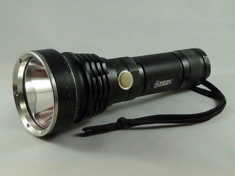
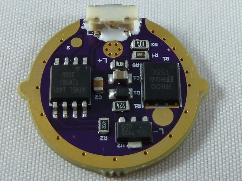
OK, the slightly used Y3 upgrade came out great!

After it's all modded/cleaned up:

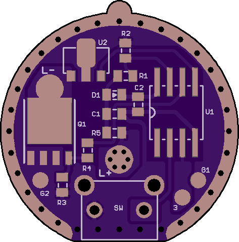
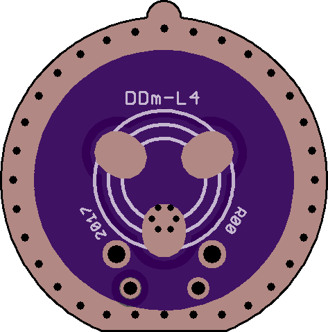
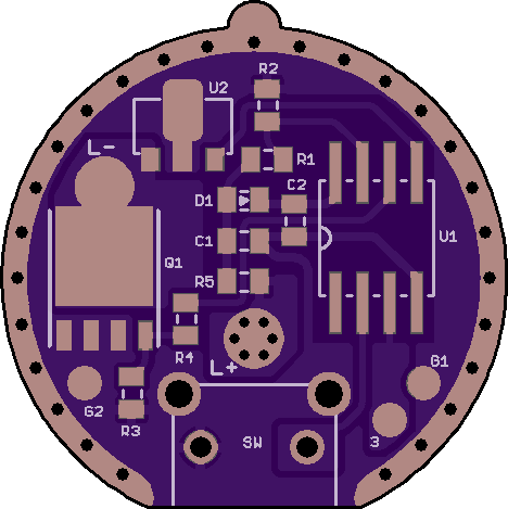
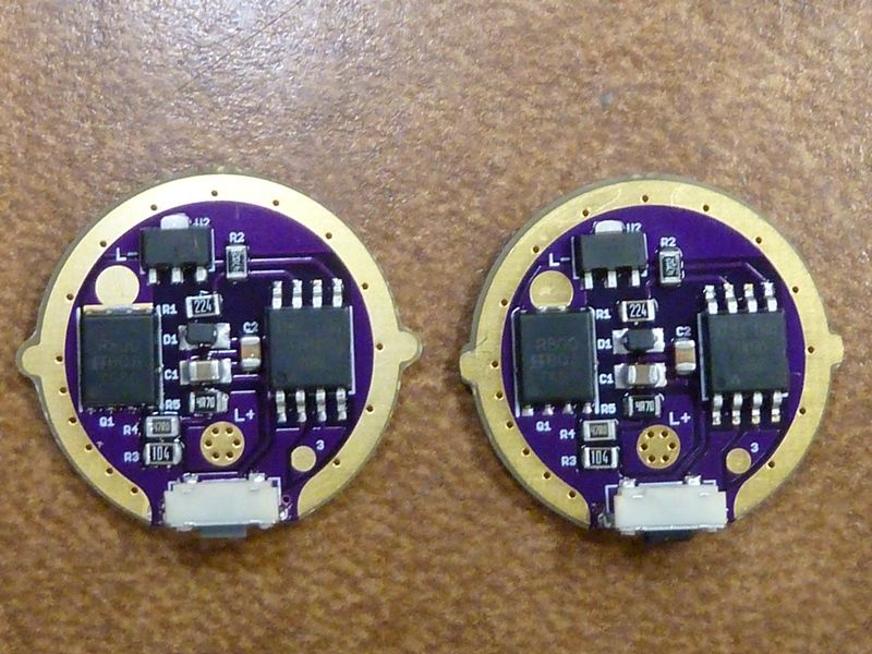
I did 2 boards. Will get to the 2nd some day:

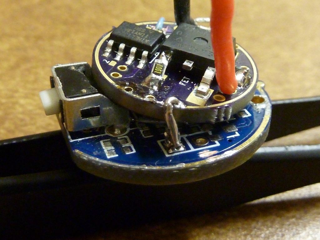
I used Arctic Alumina epoxy to sure up the switch:

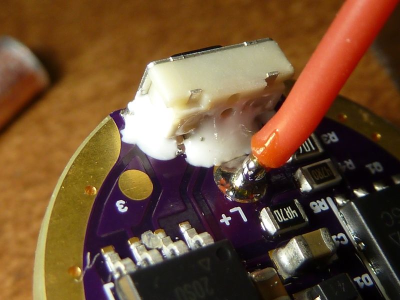
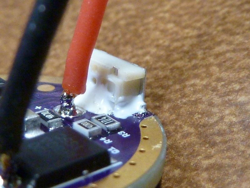
22 AWG bypass on the spring. I also applied some solder paste on one side of the LED+ pad, then the iron on the other - think the holes filled up well w/solder. The bypass is soldered to the pad with the thru holes, so minimum path to the LED wire:

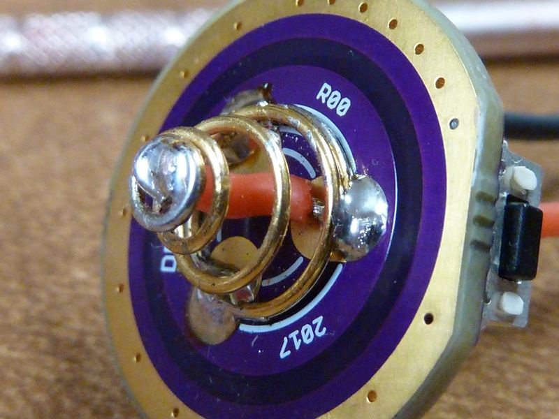
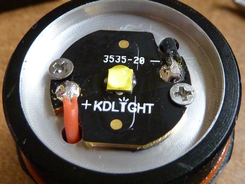
Seems to be my favorite LED right now. A KD XPL2 V6 3B, on a KD 20 mm MCPCB. Used 22 AWG because didn't think I'd get the clearance with 20 AWG. This is an early model Y3, and has a 23 mm wide flat reflector base. Later models I have use a smaller flat surface and different centering piece. The new ones need the centering piece significantly trimmed, sanded down, then the MCPCB is too low,so have to use a copper shim to elevate it. This one did not require a shim:

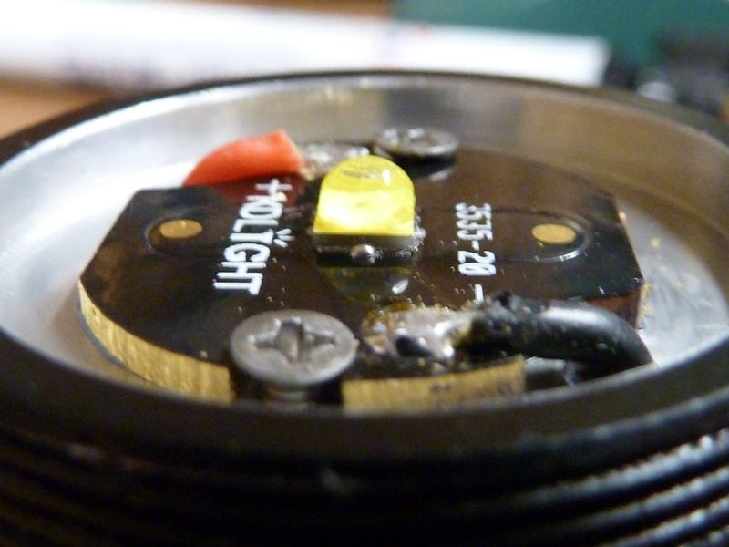
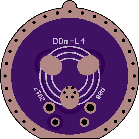
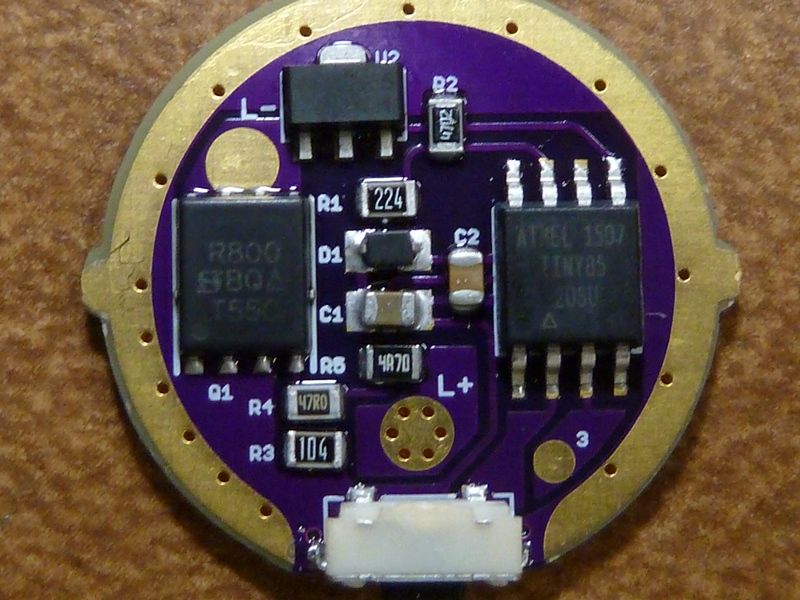
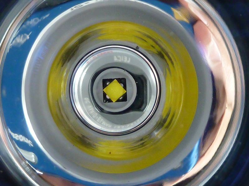
Here's a better shot in my lightbox studio on the 2nd driver:

Assembled view of the LED, 2nd in moon mode:

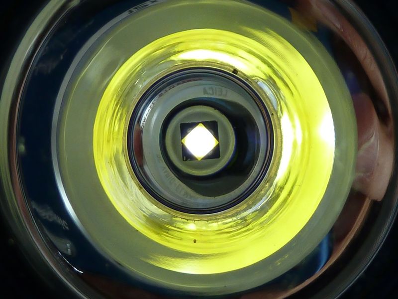
The driver fit great, nice and snug with just a little filing. The results? Well, it's impressive:

On a LK @4.20V:

  • 8.9A at the tail (clamp meter) - wow!
  • 2,280 lumens @start, 2,150 @30 secs
  • 123 kcd measured at 5m (700 meters)

Originally, this light had a Nanjg jury rigged with a FET on it, and a XM-L2 U2 1A domed. This was from May 2014. Originally, this is what it did:

On a SONY 26650 fully charged (best performing cell at the time):

  • 5.3A at the tail (DMM w/heavy gauge leads)
  • 1,680 lumens @start, 1,600 @30 secs
  • 121 kcd measured at 5m (696 meters)

So it got a 34% bump in lumens @30 secs, barely measurable bump in throw. The XPL2's don't throw as well as the XPL or XML2 - I've seen this in couple of other mods.