Hello all,
Again many thanks for all the kind words! I've been pretty busy lately but I managed to do some comprehensive testing across 20 power level settings which folks might be interested.
Before that, I want to say that I really appreciate all the comments and feedback I've received. But I'd like to reiterate that I never designed this project with an intention to sell them and make a profit, nor to produce a 'commercial' product - this was just a project I did just for fun and I did not plan to develop this extremely comprehensively and be fully featured, as I would have if I had designed this as such. As a result, I understand this driver has many flaws and 'lack of features', but I hope you can understand the motivations of the project! :) Some of you have pointed out some of the nice Russian drivers - they look great and a lot of respect to the folks who have made it as well! I'm not making this as a competitor, just making this driver as a fun project. And if people like it and would like to use the driver (with its particularities and feature (or lack of) set), or to continue to develop it, I'm more than happy to help! 
That said, given the big interest, I'll try to work a bit more on this driver and see if I can create a nice 17mm version when time allows. The use of a fairly powerful MCU also opens a lot of possibilities like soft-buttons and other features. I also made a whole bunch of PCBs (since making a batch is the same cost as making 1!), I'd be offering some for sale soon once I make sure the driver is actually worth putting into a flashlight  , so do let me know if you're interested. As a side note - what's the typical implementation of a soft button on flashlights and what should I design it for? E.g. are there any popular hosts I can take a look at that you can recommend?
Ok so back to the test!
The test was conducted as follows. The driver was hooked up to a constant voltage programmable Agilent power supply. In this case I conducted the test at 3.7V in across the range (driver was also tested at a variety of input voltage from 4.5V to <3V but less comprehensively). Input current and voltage was measured via Kelvin terminals to avoid errors due to lead resistances. Output current was measured across the load resistor as well as the output to find total driver efficiency.
A total of 20 constant current levels were tested and measurements taken.
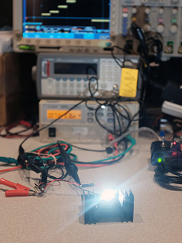
Above shows a photo of the test in action. The XHP50 LED was mounted on a 20mm star heatsink, which was in turn mounted on a big heatsink to keep it cool during tests. As a side result, the data will likely be inaccurate as the LED die temp rises, but I really don't have so much time to do a full datasheet-style test 

Here's an example scope shot showing the driver output at 5 different power levels. This was achieved by configuring the on-board MCU to run a 'test program' during startup at different power levels for 1 second each. Cyan shows output voltage and yellow shows voltage across the current sense resistor. Regulation is fairly clean, as expected with the very high switching frequency.
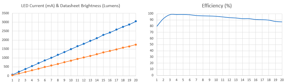
In this test, the maximum power tested was a massive 22.4W into the driver, driving the XHP50 LED at a measured 3053mA. At this power level, just putting my finger near the LED light feels very hot! Based on the specific bin of XHP50 I had on hand, this translates to a datasheet lumen output of around ~1700 lumens. Lower CRI bins less than this 90+CRI one used should yield close to 2000 lumens. As mentioned, heatsinking becomes very critical at these levels.
Maximum efficiency was measured at around 98+% efficiency at lowers loads of around 750mA out.This drops gradually to 87% or so at 3A output, meaning about 2W dissipated in the driver itself! Most of the heatsinking of the driver occurs through the ground ring around the driver so mounting it in a host properly is also critical. Increased temperature after longer runs will certainly affect the efficiency though. In all the driver seemed to regulate current just fine all the way up to the maximum 3A load. Finally, keep in mind that this efficiency number should probably be treated more as a guideline. I expect the efficiency to actually be better since there probably is non-trivial ohmic losses in connection points / spring, and a properly seated driver in a good host with a good switch should do a little better. So this efficiency is the measured system efficiency, driver efficiency should be a little higher (esp on the high currents). Finally the shape looks roughly in-line with my simulations should it at least gives me a good confidence in my measurements. Overall approaching 90% system efficiency is still pretty good for me!
In reality, I will likely turn operating current down to closer to 1.8A for a total lumen output of just around 1000 lumens of 90CRI light! This is due to the relatively poor heatsinking design of the host. Perhaps one day I'll mod this into a 'real' flashlight!
Overall I'm quite happy with the results as they are around the ballpark of what I expected, and most of all, I'm very glad that I didn't mess up the PCB (which is pretty rare given that this is my first run!). The next step is to work on the firmware for modes, and finish a more detailed write-up on the driver. I'll also be finally putting this LED driver into a host and do some beam comparison shots with the stock 'LatticeBright' LED and its driver, with this new driver!
More to come soon and thanks for reading.


