Nahh, neither of the above. Mine are built for the tailcaps with little other consideration. There’s no “seal” in there at all apart from a small bit of nylon glove, so there’s less filtering but also less waterproofing. On top of that I’m running them pretty strong, several mA each. They’re crazy-inefficient and I have to charge the batteries in them every few weeks, even if I don’t use them at all. But they are pretty bright. If you look back at my build info, you can see that I’m using a 200 ohm bleeder resistor on a driver that’s generally considered to not even need one. That’s just to get the power up for the tails. So yeah I can easily see them across my bedroom at night. They’re not nearly as noticeable in a lighted room though, for sure.
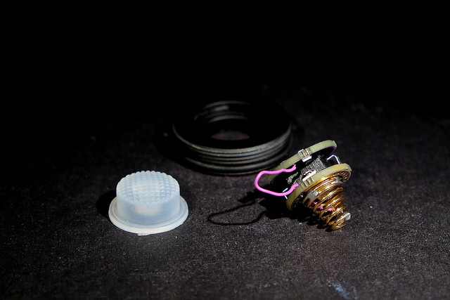
Finally put a lighted tailcap in my S41S. Placed a 750ohm smd on the battery side of the driver with a tiny drop op superglue so wont move and touched the ends with a drop of solder on my tip.
Thanks again budgetlightforum :+1: .
TA Bistro driver,BR=470R
Operation is not normal, bounce!?

What do you mean by bounce?
If the tailcap is too bright it will cause issues with reverse modes. I find that keeping it under ~.4ma works best with a 560ohm bleeder.
The flashlight is almost no action, press a few times, sometimes it will light.
The position of the switch is 1
Current limiting resistor is 20K*2
50K VR =0K
We need a recipe table. This one works good for me:
2 Orange LED's - 56K ohm
2 Green LED's - 220K ohm
2 Blue LED's - 100K ohm
Output is nicely balanced when cell is full. When only Orange is clearly illuminated, cell is about half way drained.
TA, (of course I could check this myself :innocent: ), do your FET+1 drivers have the ‘fix’ with the 5-10 Ohm resistor between led+ and C1/S1? That fix makes the driver way more tolerant for the lighted tailcap.
(sorry if this a way old discussion long past, I do not follow it all)
Yep, this was actually one of the largest reasons for building the TA drivers, to get rid of the instability issues at high amps.
It has both the “R5” resistor along with the C2 and FET resistors to further improve stability. I have not had an issue with stability on the TA drivers even up to 30A.
Although most if not all the issues with the lighted tailcap stem from the use of the OTC. The latest firmware that is being worked out should eliminate the OTC and thus fix all the lighted tailcap issues along with all the timing issues.
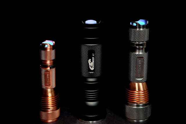
OK so please forgive me as I am very new to this lighted tail cap. It is very cool so I have to try it. I’m trying to use Rev 5.3 to light up some S2+ metal tail caps.
So far I have orange LEDs soldered to channel 1 and that is all I want to do for now. I have had the tail cap together and the flashlight works but no tail cap illumination….I’m assuming I”m going to need a bleeder which I’ll get to that in a second. Can anyone help me with these questions:
1) does the switch allow me to change channels? If i have orange LEDs on channel 1 and blue LEDs on channel 2 will the switch let me have just one channel illuminated at a time?
2) I get the POT let’s me adjust the current for each channel, so can I just bypass the resistor pads?
3) If using a POT does that mean I have to jump the P next to the channel 2 resistor pads?
4) I’m using a DrJones H17F driver (amazing driver) so where would I put the bleeder?
Thanks in advance for putting up with me
SG3
I haven’t used the H17F yet, so I can’t comment on that.
The illumination should still work even without the bleeder. The bleeder is supposed to help with mode switching/memory.
If you’re only using three LEDs, there’s no need to jump the P pad. That’s for when you want to run all 6 LEDs off one resistor.
The pot feeds both channel 1 and 2. If you don’t need to “balance” the channels, you may not need to use a separate resistor.
You can’t change channels back and forth via the switch.
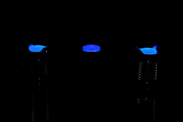
Are you sure the tailcap isn’t lighting up? They can be a bit difficult to see with the metal tailcap unless you have the juice cranked up high. I’d bench test that guy if you haven’t already. Carefully hook up leads to a battery (don’t short them!) and then hook the leads to the switch or boards. Make sure it’s working outside of the light before you install it.
Thanks for the response and help. Not sure it’s lighting up or not. I’m not sure how to test it outside the light. I know you explained how to do this but I still don’t follow lol. I did light the LEDs up with my multimeter via the anode and cathode.
So if I want to run a resistor, don’t use a POT and if using a POT just jump the resistor pads?
So what does the switch do? I’m also confused on why there are 2 POT pads.
Maybe it is working but I just couldn’t see it. Maybe I’ll try all 6 LEDs.
I think 5.3 just has too many options for me lol
The switch allows you to switch between which pot you are using. For example you could set a high and low mode. Or not install one pot so you have on and off.
You can still use resistors for balancing. Or you can bypass them and the a pot will control the resistance.
You seem confused if your boards are working. What components do you currently have attached and what is bypassed?
Right now I have LEDs on channel 1. Switch installed, POT on channel one, P jumped and both resistors jumped. Sounds like I have it right. Maybe I just need to crank up the juice or add some LEDs.
So to test it outside the light can I just put some leads on the spring and ground of the PCB and touch the leads to a battery?
Or maybe I need to unjump P?
If you jump P I dont think you have to jump both resistors, but maybe I am wrong, yeah try it outside the flashlight exactly how u said.
Jumping P doesn’t really make any difference in this situation. It’s just used when you’re using 6 LEDs and want to run them off a single resistor (or single jumped resistor pad).
Yeah, try a bench test. Hook up your negative lead to the spring. Connect positive to the grounding ring. * Make sure the switch is off or you’ll end up with a short & sparks!*
I am having problems. I built a complete 5.3 with a 5k ohm resistor on both channel. I bypassed one pot and that whole setup works great. When I put it in the flashlight everything works OK but when I turn the light off and then back on it acts as if I do a long press. I am using a MTN FET+1 driver and have a 500 ohm bleeder. Should I go lower and how much lower. Also if anyone could recommend where to put the resistor that would be great.
None of the H17f drivers I have in lights with lighted tailcaps need a bleed resistor. I always use a 560 on the driver and adjust the tailcap resistors to control brightness.
So I can just get the H17F driver from mtn and not worry about a bleeder?
So far, that has been the case for me. I have 3 running that way, but YMMV