Thanks for your comments and suggestions - here's a quick response to your questions. I say quick because I'm about done with a more detailed write up, though as I've found, the documentation is taking -wayy- more time than I had expected, and certainly much more than actually making the driver in the first place. I'm glad to have found this forum since it's given me a lot more motivation to work on this project and to hopefully make a 'commercial quality' product in the end instead of just an experimental hobby project.
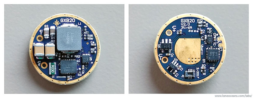
About the digital potentiometer, - that's correct, when I was first designing the GXB20, keep in mind I did the entire schematic and layout all in a single day when I had nothing to do... I wasn't really expecting this to work as well as it did, but I didn't put as much thought into in as I would have for a product like this (since I was just making it for fun). Back then I wasn't aware of the flashlight community so I didn't think too much about the levels, and ramping etc.
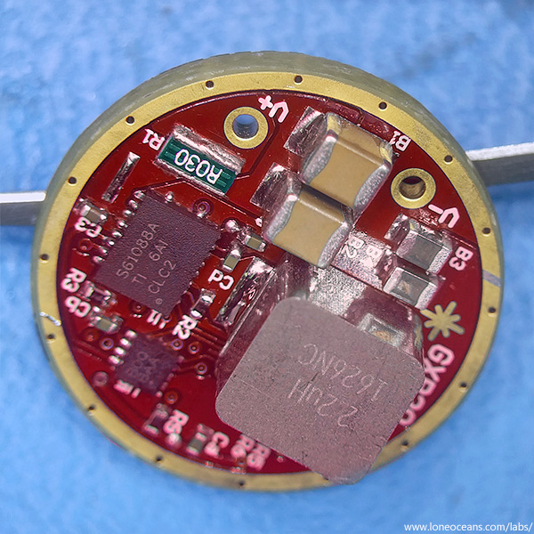
The digi-pot works in conjunction with an op-amp as a variable gain amplifier. There are some limitations as I have found, i.e. the gain adjustment was a little too cramped at the low end. I found that values 0 to 20 get you about the full range to 3A output. However you can increase this further by changing the current sense resistor to say 60mR, which would give you 0 to 40 but twice as much power dissipation in the sense resistor. Regardless, I do have plans to re-do this section to make use of the full 256 taps :). I also need to analyze the feedback more carefully to ensure that the system keeps within regulation and the loop response is kept in check.
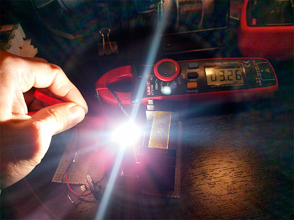
The limit of the driver depends on various factors - power / heat dissipation, saturation of the inductor, PCB trace thickness etc. But as-is, the limit is currently set by the input current limit which is set via the 115kR resistor for just about 9A input. So it should be able to handle ~4A+ output, so I haven't tested it just yet. As for why it's 2770mA, that was due to a modification I made to the driver to test! Nominally writing 20 to the digipot with the default schematic values should give around 3A out. One of the main limitations I found with the digipot is the very high wiper resistance, especially at low drive voltages. So I'm looking to replace this part with another one. I'll update the firmware to reflect more accurate values. :)
[edit] - My page has been updated with refined V0.9 firmware and code. Please discard the older one which was still under development.
As for boosting to 6V to 12V or 3V to 12V, this is all possible with this driver but I don't have a simple answer for it, since I'll have to redo the math on the magnetics to make sure they check out ok. But is it possible with some modifications, yes.
I prefer Atmel Studio as well, but I decided to do it in the Arduino IDE because it's much more hobbyist friendly, so I thought that would be useful. Regardless this should be very straightforward to just port to use in Atmel Studio, or in fact any of your favourite IDEs.
Finally, your last question on PWM - no the LED receives a regulated constant current supply. You are right in that the switching state of the FETs in the converter operates like a PWM at the switching frequency. However the inductor in the boost circuit is key - it resists sudden changes in current flowing through it. So while the voltage across the inductor can look like a PWM, the output is sustained by both the output capacitor and the inductor current. As long as the time constant of the RC output is high compared to the switch period, the output voltage approaches a constant DC output voltage.

As you can see above, the cyan line shows the output voltage, and you can see that the ripple looks to be fairly decent with no PWM :).
If you'd be interested in boards I can certainly send them to Sweden in a regular envelope. Drop me a PM if you'd like :)
To conclude - I understand that there are certainly many improvements I can do to the GXB20 and I welcome all criticism and comments! I'm definitely not the best firmware and/or electrical engineer since I'm just doing this for fun, but it's been a lot of fun and if I can make something that the community can use, I think it's a worthwhile endeavor and hopefully people better than myself can use the details I've released as a starting point or even just for inspiration. Thanks!