There are other well-known highly efficient drivers which make use of low ohmic value sense resistors: the LD-29 and LD-29S buck drivers. You may want to take a peek at the way these resolve the digipot + operational amplifier dyad, since they equip R025 and R020s.
Efficiency is key to power handling. Since usually only a reduced amount of power can be wasted in the driver, it becomes clear high efficiency is a must for high power output drivers (and hell, preferably for any power level). This remembers me I'd been thinking in a way to get rid of the sense resistor. Please bear in mind I may speak some bollocks due to lack of proper technical background but, wouldn't it be possible to use the actual inductor direct current resistance (DCR) to feed the operational amplifier? This, of course, would require placing the inductor on the low side, or switching to difference/instrumentation amplifier setups.
By the way, 80mΩ on the torch's switch sucks. It may be time for a change to FET tail switches, there are some good & cheap small FETs with very low ESR which could be parallelled and gate driven with tiny button cells (a couple in series CR1620s, for example). Sounds right?
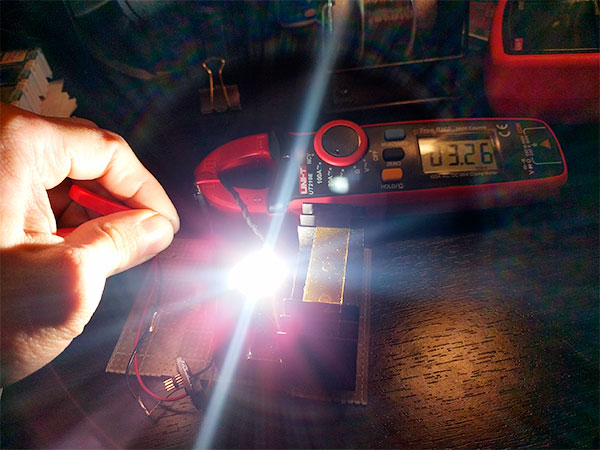
To quickly answer the question if I could drive the LED higher, I quickly did a test. I wanted to see what would happen with ~24W into the driver.
Driver seems to work just fine. This was with a measured 3.8V in at 6.32A, and as you can see an LED current of 3.26A with ~1850+ lumens of CRI90 light. Total efficiency was just around 88-89% including some LED wire loss, which is not too bad but still significant ~2.6+W dissipated just in the driver and wires! Things get warm fast, but the driver seems to handle it ok :)
Great job Loneoceans! Very impressive! Welcome to BLF! BTW, I do have small springs if you need some. Let me know what size you are looking for. You can PM me and I could send them to you free if you’re in the USA.
Nice work, thanks for sharing. Sitting under a hot LED encased in a host with no air flow. I think drivers bleeding out that much heat might need potting. A few good materials out there should nip frying in the bud.
I bought a bunch of ATtiny84A MCUs :). Let me know if anyone is interested in a board with populated and programmed MCU (only MCU, you need to solder on the rest yourself) :). The rest of the details and BOM can be found here: www.loneoceans.com/labs/sales/gxb20v1
So... I made a whole bunch of improvements to the GXB20 V1..
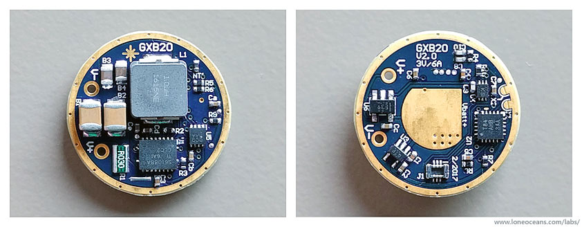
I just received the news PCBs for it... introducing the new GXB20 V2!
Still writing the (improved) firmware with a lot more additional and optional functionality, this time with 3 extra mode selection jumpers or E-switch control. And a complete layout redesign, on-board programming connection which will hopefully be a lot easier to use, and improved power electronics.
Hello, yes there were some slight changes in the feedback and digital potentiometer allowing for more variations in brightness. I also conducted some experiments in the power section but I don't think there are any hardware changes needed to be made so far (some changes I made resulted in same or slightly less efficient results so the original is good enough :) )
Another quick update and thanks again to everyone who's been following this project!
GXB20Version 2
In short, the changes I've made for the V2 version turned out to be an improvement over the original by a small amount, and after a little more testing I think I'm happy with the result for now, and the GXB20 driver has achieved all the goals I had set out at the beginning of the project!
By no means is this a complete nor 'commercial' driver, which will certainly require a little more optimization and better firmware, but I think I'm quite happy with how it is as-is, for a hobby project. Currently I'm working on finishing a more complete write-up on this driver, and will be publishing everything open-source for all to use and to fabricate boards (e.g. from OSHpark).
Some notes on the additional improvements of the GXB20 V2:
Better placement and layout (I hope!)
Much more levels of constant current brightness (256, adjustable using 1 resistor)
Improved lowest level of CC brightness (just around 1mA - true 'firefly' mode)
Modes for my own firmware: 1 = firefly <1mA, 2 = low ~180mA, 3 = mid ~600mA, 4 = ~1.8A (~1000 lumens), 5 = 3A (turbo)
Measured efficiency of 92% at 3A (~6.5V) output
Two new solder-bridge mode jumpers + extra GPIO for easy mode selections
(needs more firmware work to take advantage of all of these)
New 0.4mm pitch micro programming header for ATtiny84A
Works better at lower voltages when approaching 2.5V
+ maintains all the features of the original GXB20 V1
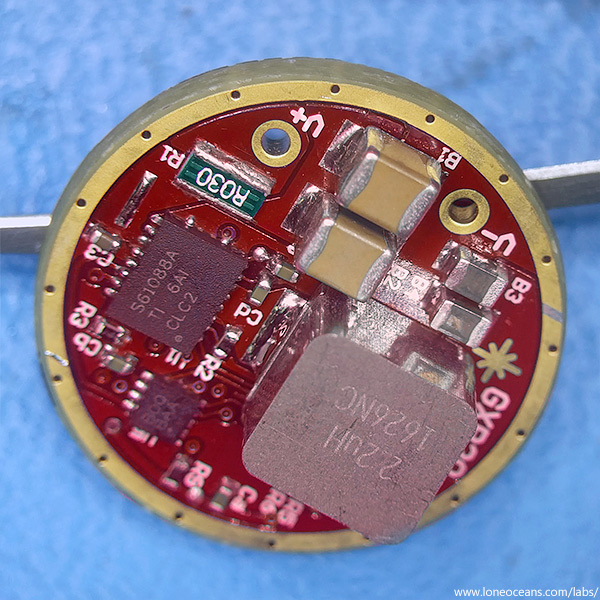
I did some experiments in the power section but it turns out that they didn't make too much of a difference (e.g. in the previous post you can see I used a bigger inductor but didn't see much benefit). The final improvement I'd probably want to do with this driver is to fabricate using half-thickness (0.8mm) PCB and 2oz copper, and of course continual work on the firmware to improve things further like adding more modes and improving EEPROM performance using a random hopping scheme.
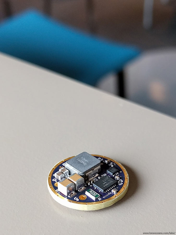
Finally, above is another view of the GXB20 V2 driver.